Note: Descriptions are shown in the official language in which they were submitted.
1
STATOR FOR A PLANAR MOTOR
Technical Field
The present invention relates to a stator assembly of an electrical
planar motor and to a stator module of an electrical planar motor.
Background
Planar drive systems having electrical planar motors may, amongst
others, be used in automation technology, in particular in manufac-
turing technology, handling technology and process technology. By
means of planar drive systems, a moveable element of a facility or
machine may be moved or positioned in at least two linearly inde-
pendent directions. Planar drive system may comprise a permanently
energized electromagnetic planar motor having a planar stator and a
rotor that may be moved in at least two directions on the stator.
In a permanently excited electromagnetic planar motor, a driving
force is exerted upon the rotor by energized conductors magneti-
cally interacting with drive magnets of a magnetic arrangement. The
present invention particularly relates to embodiments of planar
drive systems in which the drive magnets of an electrical planar
motor are arranged at the rotor and the energized conductors of the
planar motor are arranged in a stationary planar stator.
In such a drive system, the rotor comprises at least one first mag-
netic unit for driving the rotor in a first direction and a second
magnetic unit for driving the rotor in a second direction that is
linearly independent from the first direction, e.g. in a direction
orthogonal to the first direction. The planar stator comprises at
least a group of first energizable conductors which magnetically
interact with the magnets of the first magnetic unit in order to
drive the rotor in the first direction, as well as a group of sec-
ond energizable conductors magnetically interacting with the mag-
nets of the second magnetic unit in order to drive the rotor in the
second direction. The first and second groups of conductors may in
CA 3106724 2021-03-31
i
i
2
general be energized independently from each other in order to al-
low for the rotor to move in the first and second direction inde-
pendently from each other. If the conductors of the first and sec-
ond group themselves may at least in parts be energized inde-
pendently from each other, a plurality of rotors may be moved on a
stator independently from one another at the same time.
The publications WO 2013/059934 Al, WO 2015/017933 Al,
WO 2015/179962 Al, WO 2015/184553 Al, WO 2015/188281 Al,
WO 2017/004716 Al each describe planar drive systems (displacement
devices) which comprise an electromagnetic planar motor with a per-
manently energized rotor and a stator comprising a plurality of en-
ergizable conductors.
Summary of the Invention
The object of the present invention is to provide a stator assembly
and a stator module for an electrical planar motor.
In one embodiment of the present invention there is provided a sta-
tor assembly for driving a rotor of an electrical planar motor,
wherein the stator assembly comprises a first arrangement of longi-
tudinal stator layers and a second arrangement of oblique stator
layers, wherein the longitudinal stator layers comprise first coil
conductors and wherein the oblique stator layers comprise second
coil conductors, wherein the second coil conductors are embodied to
interact with second drive magnets of the rotor in order to drive
the rotor in a first direction, wherein the first coil conductors
are embodied to interact with the first drive magnets of the rotor
in order to drive the rotor in a second direction differing from
the first direction, wherein the longitudinal stator layers and the
oblique stator layers are arranged on top of one another in a third
direction oriented perpendicularly to the first and second direc-
tion, wherein the longitudinal stator layers and the oblique stator
layers have the same mean distance from a stator surface of the
stator assembly in the third direction.
CA 3106724 2021-03-31
t
i
3
A stator assembly for driving a rotor of an electrical planar motor
comprises a first arrangement of longitudinal stator layers and a
second arrangement of oblique stator layers. The longitudinal sta-
tor layers comprise first coil conductors and the oblique stator
layers comprise second coil conductors. In this context, the second
coil conductors are embodied to interact with second drive magnets
of the rotor in order to drive the rotor in a first direction, and
the first coil conductors are embodied to interact with first drive
magnets of the rotor in order to drive the rotor in a second direc-
tion differing from the first direction. The longitudinal stator
layers and oblique stator layers are arranged on top of one another
in a third direction oriented perpendicularly to the first and sec-
ond direction. In the third direction, the longitudinal stator lay-
ers and the oblique stator layers have the same mean distance from
a stator surface of the stator assembly.
In this context, the mean distance of the longitudinal stator lay-
ers is the mean value of all distances of the individual longitudi-
nal stator layers from the stator surface. The mean distance of the
oblique stator layers is the mean value of all distances of the in-
dividual oblique stator layers from the stator surface.
If the longitudinal and the oblique stator layers have the same
mean distance with regard to the stator surface of the stator as-
sembly, a drive current in the first coil conductors of the longi-
tudinal stator layers exerts approximately the same force onto a
rotor arranged above the stator surface as the same drive current
in the second coil conductors of the oblique stator layers in the
first direction. The result may be an approximately symmetrical
transfer of force onto the rotor.
In a further embodiment of the stator assembly, the first arrange-
ment of longitudinal stator layers and the second arrangement of
CA 3106724 2021-03-31
4
oblique stator layers have a shared central plane and the longitu-
dinal stator layers and the oblique stator layers are each symmet-
rical in the third direction with regard to the shared central
plane.
By respectively arranging the longitudinal stator layers and the
oblique stator layers symmetrically around the shared central
plane, the first arrangement of longitudinal stator layers as well
as the second arrangement of oblique stator layers have the same
mean distance from the stator surface and from a rotor of the pla-
nar motor arranged in the third direction above or below the first
and second arrangement.
In the resulting symmetrical arrangement of the longitudinal stator
layers and the oblique stator layers around the shared central
plane, an approximately symmetrical transfer of force onto the ro-
tor may be achieved in the first and second direction in a simple
manner.
In a further embodiment of the stator assembly, a first total num-
ber of longitudinal stator layers and a second total number of
oblique stator layers are equal. This allows for particularly uni-
form energizing of the coil conductors of the longitudinal stator
layers and of the oblique stator layers.
In a further embodiment of the stator assembly, an topmost stator
layer of the stator assembly and a lowermost stator layer of the
stator assembly are each embodied as a longitudinal stator layer
having first coil conductors, and a second topmost stator layer of
the stator assembly and a second lowermost stator layer of the sta-
tor assembly are each embodied as an oblique stator layer having
second coil conductors. In particular, a longitudinal stator layer
as well as an oblique stator layer are positioned particularly
close to the rotor.
CA 3106724 2021-03-31
,
A further embodiment of the stator assembly comprises inner layers
arranged inside of the stator assembly, wherein the inner layers of
the stator assembly are each alternatingly embodied as two adjacent
oblique stator layers and as two adjacent longitudinal stator lay-
5 ers.
As a result, the oblique stator layers and the longitudinal stator
layers are distributed particularly homogeneously over the stator
assembly in the third direction. If the inner layers of the stator
assembly each alternatingly comprise two adjacent longitudinal sta-
tor layers and two adjacent oblique stator layers, the stator as-
sembly has a lower number of layer changes from longitudinal to
oblique stator layer. As a result, the parasitic capacitance of the
oblique and of the longitudinal stator layers decreases so that the
coil conductors may be energized by an alternating current with
particularly low loss. This is particularly the case if all first
coil conductors of the longitudinal stator layers arranged on top
of one another in the third direction and all second coil conduc-
tors of the oblique stator layers arranged on top of one another in
the third direction are connected in series or in parallel so that
direction and strength of current are respectively identical in all
first coil conductors arranged on top of one another in the third
direction and in all second coil conductors arranged on top of one
another in the third direction.
In a further embodiment of the stator assembly, the first coil con-
ductors are embodied as elongated conductor strips and/or conductor
paths extending along the first direction and the second coil con-
ductors are embodied as elongated conductor strips and/or conductor
paths extending along the second direction. This allows for a par-
ticularly space-efficient arrangement of the coil conductors of the
longitudinal and oblique stator layers.
In a further embodiment of the stator assembly, the first arrange-
ment has six longitudinal stator layers and the second arrangement
CA 3106724 2021-03-31
6
comprises six oblique stator layers. Such a stator assembly has a
compact design in the third direction and may at the same time
transmit a high force onto the rotor.
A further embodiment of the stator assembly may be embodied as a
multi-layer circuit board. Such a stator assembly may be manufac-
tured particularly simply and inexpensively.
A stator module for driving a rotor of an electrical planar motor
comprises a stator assembly. The stator assembly comprises a first
arrangement of longitudinal stator layers and a second arrangement
of oblique stator layers. The longitudinal stator layers comprise
first coil conductors and the oblique stator layers comprise second
coil conductors. In this context, the second coil conductors are
embodied to interact with second drive magnets of the rotor in or-
der to drive the rotor in a first direction, and the first coil
conductors are embodied to interact with first drive magnets of the
rotor in order to drive the rotor in a second direction differing
from the first direction. The longitudinal and the oblique stator
layers are arranged on top of one another in a third direction ori-
ented perpendicularly to the first and second direction. In the
third direction, the longitudinal and oblique stator layers have
the same mean distance from a stator surface of the stator assem-
bly.
In such a stator module, an approximately symmetrical transmission
of force onto the rotor may be achieved by means of the stator as-
sembly.
Brief Description of the Drawings
In the following, the invention will be described in more detail
using embodiment examples and referring to drawings. In this con-
text, the drawings schematically show:
CA 3106724 2021-03-31
7
Fig. 1 a perspective top view of a planar drive system having a
stator module and a rotor;
Fig. 2 a perspective bottom view of the rotor of the planar drive
system having a magnetic arrangement;
Fig. 3 a perspective top view of the stator module of the planar
drive system;
Fig. 4 an exploded view of a stator assembly of the stator module
with a first, second, third and fourth stator layer;
Fig. 5 the stator layers of a first stator sector of the stator
assembly having individual stator segments;
Fig. 6 the stator assembly in a sectional view;
Fig. 7 a first further stator assembly for the stator module in a
sectional view;
Fig. 8 a second further stator assembly for the stator module in
a sectional view;
Fig. 9 a third further stator assembly for the stator module in a
sectional view;
Fig. 10 a fourth further stator assembly for the stator module in
a sectional view;
Fig. 11 a fifth further stator assembly for the stator module in a
sectional view;
Fig. 12 a sixth further stator assembly for the stator module in a
sectional view; and
Fig. 13 the first further stator assembly in a further sectional
view.
Detailed Description of Preferred Embodiments
The present invention essentially relates to further developments
of the planar-drive systems disclosed in publications
WO 2013/059934 Al, WO 2015/017933 Al, WO 2015/179962 Al,
WO 2015/184553 Al, WO 2015/188281 Al and WO 2017/004716 Al.
Furthermore, the present invention relates to further developments
of planar-drive systems disclosed in German patent applications
CA 3106724 2021-03-31
,
8
2017 131 304.4, 10 2017 131 314.1, 10 2017 131 320.6,
10 2017 131 321.4, 10 2017 131 324.9 and 10 2017 131 326.5.
Fig. 1 shows a perspective top view of a planar-drive system 1 hay-
5 ing a stator module 10 and a rotor 200. The stator module 10 com-
prises a module housing 19 and a stator assembly 100. The stator
module 10 comprises an upper side 8 and a bottom side 9 opposite to
the upper side 8. The stator assembly 100 is arranged above the
module housing 19 and at an upper side 8 of the stator module 10 in
10 a third or vertical direction 15 oriented from the bottom side 9 to
the upper side 8. The stator assembly 100 is embodied as a planar
stator and comprises a planar stator surface 11 on the upper side 8
of the stator module 10. The stator surface 11 simultaneously forms
a surface of the stator module 10.
The stator surface 11 is oriented vertically with regard to the
third direction 15 and extends over the entire upper side 8 of the
stator assembly 100 and of the stator module 10. The stator assem-
bly 100 comprises on the stator surface 11 at least one first coil
conductor 125 energizable with a drive current. As shown, the sta-
tor assembly 100 may comprise a plurality of first coil conductors
125 on the stator surface 11. The first coil conductors 125 may
each be energized with a drive current. By means of the drive cur-
rents in the first coil conductors 125, a magnetic field may be
generated which drives the rotor 200 in interaction with the drive
magnets of the rotor 200 not shown in Fig. 1. The rotor 200 and the
stator unit 100 having the current-charged first coil conductors
125 form an electromagnetic planar motor.
In operation, the rotor 200 is arranged above the stator surface 11
of the stator module 10 in a moveable manner and may, in operation,
be driven in a first direction 12 as well as in a second direction
14. The first direction 12 and the second direction 14 are differ-
ent and linearly independent from each other. In particular, the
first direction 12 and the second direction 14 may, as shown in
CA 3106724 2021-03-31
9
Fig. 1, be aligned perpendicularly to each other. The first direc-
tion 12 and the second direction 14 are each oriented in parallel
to the stator surface 11 and perpendicularly to the third direction
15. By driving the rotor 200 in the first direction 12 as well as
in the second direction 14, the rotor 200 may be driven in any de-
sired direction via the stator surface 11. The rotor 200 may in op-
eration be kept in a floating position over the stator surface 11,
e.g. by means of a magnetic interaction between the drive magnets
and suitable drive currents in the first coil conductors 125. Apart
from driving the rotor 200 in the first and second direction 12,
14, it is also possible to drive the rotor 200 in a third, vertical
direction 15.
The stator surface 11 has a rectangular embodiment. In particular,
the stator surface 11 may, as shown, have a square shape. The sta-
tor surface 11 is delimited by four respectively straight outer
edges 30. Two opposite outer edges 30 are respectively in parallel
to the first direction 12 and two opposite further outer edges 30
are respectively in parallel to the second direction 14.
An extension of the stator assembly 100 in the third direction 15
is smaller than an extension of the stator assembly 100 in the
first and second direction 12, 14. The stator assembly 100 thus
forms a flat cuboid extending in the first and second direction 12,
14 or a plate extending in the first and second direction 12, 14.
Between the stator surface 11 and a bottom side of the stator as-
sembly 100 opposite to the stator surface 11, the stator assembly
100 comprises four respectively planar side surfaces 32 that are
flush with the outer edges 30 of the stator surface 11 at the sta-
tor surface 11. The side surfaces 32 of the stator unit 100 are
perpendicular to the stator surface 11.
The module housing 19, as the stator surface 11 and the stator as-
sembly 100 in a top view onto the stator surface 11, has a rectan-
gular embodiment. The module housing 19 particularly has a square
CA 3106724 2021-03-31
10
shape in a top view of the stator surface 11. The module housing 19
is embodied as a flat cuboid or, respectively, as a plate wherein
the extension of the module housing 19 is smaller in the third di-
rection 15 than in the first and second direction 12, 14. An upper
side of the module housing facing the stator assembly 100 is ar-
ranged adjacent to the bottom side of the stator assembly. In the
first and second direction 12, 14, the stator unit 100 and the mod-
ule housing 19 essentially have the same dimensions.
Between the upper side of the module housing 19 facing the stator
assembly 100 and a bottom side of the module housing 19 opposite to
the upper side, the module housing 19 comprises four respectively
planar side faces 34. The side faces 34 of the module housing 19
may, as shown, be oriented perpendicularly to the stator surface
11. The side faces 34 of the module housing 19 may be aligned flush
to the side faces 32 of the stator assembly 100 and be adjacent to
the side faces 32 of the stator assembly 100. In an alternative em-
bodiment of the stator module 10 (not shown), the side faces 34 of
the module housing 19 may also be set back with regard to the side
faces 32 of the stator assembly 100 to the interior of the stator
module 10. In a further alternative embodiment (not shown), the
side faces 34 of the module housing 19 may be arranged at to the
upper side of the module housing 19 adjacent to the side faces 32
of the stator assembly 100 and may taper perpendicularly to the
third direction 15 towards the bottom side of the module housing 19
in the direction of the interior of the stator module 10.
The stator module 10 has a rectangular embodiment in a top view of
the stator surface 11. The stator module 10 comprises four respec-
tively plane side faces 36 between the stator surface 11 arranged
at the upper side 8 of the stator module 10 and the bottom side 9
of the stator module 10 arranged opposite to the upper side 8. The
side faces 36 of the stator module 10 are formed by the side faces
32 of the stator assembly 100 in the area of the stator assembly
CA 3106724 2021-03-31
. s
11
100 and by the side faces 34 of the module housing 19 in the area
of the module housing 19.
At the stator surface 11, the side faces 36 of the stator module 10
are thus flush with the outer edges 30 of the stator surface 11 and
the outer edges 30 of the stator surface 11 at the same time form
the outer edges of the stator module 10 at the stator surface 11.
In particular, the stator surface 11 extends in the first direction
12 and in the second direction 14 between two of the side faces 36
of the stator module 10, respectively, and the outer edges 30 de-
limit the extension of the stator surface 11, of the stator assem-
bly 100 and of the stator module 10 at the side faces 36 of the
stator module 10 in the first direction and in the second direction
14.
As shown, the side faces 36 of the stator module 10 may each be
aligned perpendicularly to the stator surface 11. In alternative
embodiments of the stator module 10 (not shown), the side faces 36
of the stator module 10 in the range of the module housing 19 may
be set back in the direction of the interior of the stator module
10 and may taper from the upper side 8 to the bottom side 9 in the
direction of the interior of the stator module 10.
While the stator module 10 has a planar embodiment at its surface
formed by the stator surface 11, the stator module 10 may have a
non-planar embodiment at the bottom side 9 of the stator module 10
opposite to the stator surface 11. In particular, further compo-
nents may be arranged at the module housing 19 or at the stator
module 10 at the bottom side 9 of the stator module 10 or at the
bottom side of the module housing 19. In the first direction 12 or
in the second direction 14, these further components extend up un-
til the outer edges 30 of the stator assembly 100 at most so that
the further components do not protrude over the outer edges 30 of
the stator assembly 100 in the first or the second direction 12,
14.
CA 3106724 2021-03-31
12
At the bottom side of the module housing 19, connections not shown
in Fig. 1 are arranged for connecting the stator module 10 with a
plurality of connecting lines 18. The connecting lines 18 may e.g.
comprise an input line of a data network, an output line of a data
network and a power-supply line for supplying the stator module 10
with electrical power. Particularly, the stator module 10 may be
provided with electrical power to generate the drive currents by
means of the power-supply line. The stator module 10 may be con-
nected with a control unit of the planar-drive system 1 via the
data network and exchange control data with the control unit for
controlling the rotor 200.
The stator surface 11 may in the first direction 12 have an exten-
sion in a range between 100mm and 500mm, in particular between 120
mm and 350mm, in particular 240 mm. The stator surface 11 may in
the second direction 14 have an extension between 100mm and 500mm,
in particular between 120mm and 350mm, in particular 240mm. The
stator module 10 may in the third direction 15 have an extension
between 10mm and 100mm, in particular between 15mm and 60mm, in
particular 30mm. The module housing may in the third direction 15
have an extension between 8mm and 80mm, in particular between 13mm
and 55mm, in particular 26.6mm. The module housing 19 may in the
first and/or second direction 12, 14 have the same extension as the
stator surface 11. The stator assembly 100 may in the third direc-
tion 15 have an extension of lmm to lOmm, in particular 2mm to 5mm,
in particular 3.5mm to 4.5mm, in particular 3.7mm to 4mm.
Several specimens of the stator module 10 may be arranged side-by-
side in such a way that the outer edges 30 of neighboring stator
modules 10 abut on one another and the stator surfaces 11 of the
stator modules 10 form a continuous working surface over which the
rotor 200 may be moved without interruption. As the side faces 36
of the stator module 10 are flush with the stator surface 11 at the
CA 3106724 2021-03-31
13
outer edges 30, the stator surfaces 11 of two stator modules 10 ar-
ranged side-by-side may be arranged almost seamlessly in an adja-
cent manner by arranging the stator modules 10 with abutting side
faces 32 of the stator assembly 100 or with abutting outer edges of
the stator surfaces 11.
Fig. 2 shows the rotor 200 of the planar-drive system 1 in a per-
spective view from the bottom onto a bottom side of the rotor 200.
When operating the planar-drive system 1, the bottom side of the
rotor 200 faces the stator surface 11 of the stator module 10. At
the bottom side, the rotor 200 comprises a magnetic arrangement
201. The magnetic arrangement 201 has a rectangular, particularly
square, embodiment and comprises a plurality of magnets. The bottom
side of the rotor 200 has an even or, respectively, planar embodi-
ment in the area of the magnets of the magnetic arrangement 201. In
operation, the bottom side of the rotor 200 comprising the magnetic
arrangement is oriented essentially in parallel to the stator sur-
face 11 and arranged facing the stator surface 11.
The magnetic arrangement 201 comprises a first magnetic unit 210, a
second magnetic unit 220, a third magnetic unit 230 and a fourth
magnetic unit 240. The first magnetic unit 210 and the third mag-
netic unit 230 each comprise first drive magnets 211 that, in a
first rotor direction 206, have an elongated extension and are ar-
ranged side-by-side along a rotor direction 208 oriented perpendic-
ularly to the first rotor direction 206. In particular, the first
and the third magnetic unit 210, 230 may each comprise three first
drive magnets 211. The second magnetic unit 220 and the fourth mag-
netic unit 240 each comprise second drive magnets 221 that are each
arranged side-by-side in a first rotor direction 206 and have an
elongated extension along the second rotor direction 208. In par-
ticular, the second and the fourth magnetic unit 220, 240 may each
comprise three second drive magnets 221.
CA 3106724 2021-03-31
14
The first and third magnetic unit 210, 230 serve to drive the rotor
200 in the second rotor direction 208 during operation and the sec-
ond and fourth magnetic unit 220, 240 serve to drive the rotor 200
in the first rotor direction 206 during operation. The first drive
magnets 221 of the first and third magnetic unit 210, 230 and the
second drive magnets 221 of the second and fourth magnetic unit
220, 240 are each magnetized perpendicularly with regard to the
first and second rotor direction 206, 208. In this context, adja-
cent drive magnets 211, 221 of the magnetic units 210, 220, 230,
240 each comprise opposite magnetization.
Fig. 3 shows the stator module 10 of the planar-drive system 1 in a
perspective top view without the rotor 200. The stator assembly 100
of the stator module 100 comprises a first stator sector 110, a
second stator sector 112, a third stator sector 113 and a fourth
stator sector 114. The stator sectors 110, 112, 113, 114 themselves
each comprise a part of the first coil conductor 12 arranged at the
stator surface 11 of the stator assembly 100. Each of the first
coil conductors 125 at the stator surface 11 is fully arranged in
one of the stator sectors 110, 112, 113, 114. The stator sectors
110, 112, 113, 114 have a rectangular embodiment. In particular,
the stator sectors 110, 112, 113, 114 may have a square embodiment
so that an extension of the stator sectors 110, 112, 113, 114 in
the first direction 12 corresponds to an extension of the stator
sectors 110, 112, 113, 114 in the second direction 14.
The stator sectors 110, 112, 113, 114 are in the first direction 12
arranged in two side-by-side rows and in the second direction, they
are arranged adjacently to each other in two side-by-side rows, as
well. The stator sectors 110, 112, 113, 114 of adjacent rows are
arranged adjacently to each other, as well. In the first direction
12, the stator assembly 100 comprises a row having the second sta-
tor sector 112 and the first stator sector 110 and a further row
having the fourth stator sector 114 and the third stator sector
113. In the second direction 14, the stator assembly 100 comprises
CA 3106724 2021-03-31
15
a row having the first stator sector 110 and the third stator sec-
tor 113 and a further row having the second stator sector 112 and
the fourth stator sector 114.
In the first direction 12 and in the second direction 14, the sta-
tor sectors 110, 112, 113, 114 each have an extension that is half
as large as the extension of the stator assembly 100 or, respec-
tively, the extension of the stator module 10 in the corresponding
direction 12, 14. The boundaries of the stator sectors 110, 112,
113, 114 thus, in the first and in the second direction 12, 14,
each extend in the center of the stator assembly 100 and intersect
in the center of the stator assembly 100. The stator sectors 110,
112, 113, 114 each comprise a quarter of the area, i.e. a quadrant,
of the stator assembly 100.
In the stator assembly 100 of the stator module 10 shown in Fig. 3,
the stator layer at the stator surface 11 only comprises first coil
conductors 125 which have an elongated extension in the first di-
rection 12 and are arranged side-by-side and adjacently to each
other in a direction perpendicular to the first direction 12. If
the first direction 12 and the second direction 14 are oriented
perpendicularly to each other, as shown in Fig. 3, the first coil
conductors 125 are arranged side-by-side and adjacently to each
other along the second direction 14.
Apart from the first coil conductors 125 shown in Fig. 3, the sta-
tor assembly 100 comprises second coil conductors not shown in Fig.
3. The second coil conductors have an elongated extension along the
second direction 14 and arranged side-by-side and adjacently to
each other in a direction perpendicular to the second direction 14.
If the second direction 14 and the first direction 12 are oriented
perpendicularly to each other, the second coil conductors are ar-
ranged side-by-side and adjacently to each other along the first
direction 12.
CA 3106724 2021-03-31
16
Within the stator sectors 110, 112, 113, 114, the first coil con-
ductors 125 and the second coil conductors are arranged in several
overlaying stator layers or stator planes, wherein each of the sta-
tor layers each comprises either exclusively first coil conductors
125 or exclusively second coil conductors. Apart from the extension
of the first coil conductors 125 and of the second coil conductors
and to the extent that no differences are described in the follow-
ing, the stator sectors 110, 112, 113, 114 are embodied identically
on the various stator layers.
The stator layer visible in Fig. 3 at the stator surface 11 forms a
first stator layer of the stator assembly 100. In the third direc-
tion 15 below the first stator layer, the stator assembly 100 com-
prises at least a second stator layer, a third stator layer and a
fourth stator layer.
Fig. 4 shows a schematic perspective view of an exploded view of
the stator assembly 100 with individual stator layers.
The stator assembly 100 comprises, in a third direction 15, a sec-
ond stator layer 105 beneath the first stator layer 104 arranged at
the stator surface 11, a third stator layer 106 beneath the second
stator layer 105 and a fourth stator layer 107 beneath the third
stator layer 106. To the extent that no differences are described
in the following, the second, third and fourth stator layer 105,
106, 107 are embodied as described for the first stator layer 104
at the stator surface 11 of the stator assembly 100 shown in Fig.
3.
In the fourth stator layer 107, the stator sectors 110, 112, 113,
114 comprise, as in the first stator layer 104, first coil conduc-
tors 125 having an elongated extension along the first direction 12
and arranged side-by-side and adjacently to each other in the di-
rection oriented perpendicularly to the first direction 12. In the
CA 3106724 2021-03-31
17
second stator layer 105 and in the third stator layer 106, the sta-
tor sectors 110, 112, 113, 114 comprise second coil conductors 126.
To the extent that no differences are described in the following,
the second coil conductors 126 are embodied as described for the
first coil conductors 125 in the first stator layer 104 and in the
fourth stator layer 107. Other than the first coil conductors 125
of the first and fourth stator layer 104, 107, the second coil con-
ductors 126 of the second and third stator layer 105, 106 have an
elongated extension along the second direction 14 and are arranged
side-by-side and adjacently to each other in the direction oriented
perpendicularly to the second direction 14.
In the first and fourth stator layer 104, 107, the stator sectors
110, 112, 113, 114 exclusively comprise the first coil conductors
125 having an elongated extension along the first direction 12, and
not the second coil conductors 126 having an elongated extension
along the second direction 14, as well. In the same manner, the
stator sectors 110, 112, 113, 114 in the second and third stator
layer 105, 106 only comprise the second coil conductors 126 having
an elongated extension along the second direction 14, and not the
first coil conductors 125 having an elongated extension along the
first direction 12, as well.
In all stator layers 104, 105, 106, 107, the stator sectors 110,
112, 113, 114 each comprise identical dimensions. In particular,
the stator sectors 110, 112, 113, 114 each comprise identical di-
mensions in all stator layers 104, 105, 106, 107 in the first di-
rection 12 and in the second direction 14.
The number and arrangement of the first coil conductors 125 is
identical to the first coil conductors 125 in the individual over-
laying stator layers 104, 107, in particular in the first and
fourth stator layer 104, 107. In particular, the first coil conduc-
tors 125 are arranged on top of one another in the third direction
CA 3106724 2021-03-31
18
15. In addition, the number and arrangement of the second coil con-
ductors 126 is identical to the second coil conductors 126 in the
individual overlaying stator layers, in particular in the second
and third stator layer 105, 16. In particular, the second coil con-
ductors 126 are arranged on top of one another in the third direc-
tion 15.
The coil conductors 125, 16 of stator layers 104, 105, 106, 107 ar-
ranged on top of one another are each electrically isolated from
one another. For example, the stator assembly 100 may be embodied
as a multi-layer circuit board and the stator layers 104, 105, 106,
107 may each be embodied as conductor layers of the multi-layer
circuit board that are isolated from one another.
The stator sectors 110, 112, 113, 114 may be energized inde-
pendently from one another. In particular, the first coil conduc-
tors 125 and the second coil conductors 126 of the stator sectors
110, 112, 113, 114 are electrically isolated from one another on
the stator assembly 100. This particularly means that the coil con-
ductors 125, 126 of the first stator sectors 110 are electrically
isolated from the coil conductors 125, 126 of the second stator
sector 112, from the coil conductors 125, 126 of the third stator
sectors 113 and from the coil conductors 126, 126 of the fourth
stator sector 114. In addition, the coil conductors 125, 126 of the
second stator sector 112 are electrically isolated from the coil
conductors 125, 126 of the first stator sector 110, from the coil
conductors 125, 126 of the third stator sector 113 and from the
coil conductors 125, 126 of the fourth stator sector 114. In addi-
tion, the coil conductors 125, 126 of the third stator sector 113
are electrically isolated from the coil conductors 125, 126 of the
first stator sector 110, from the coil conductors 125, 126 of the
second stator sector 112 and from the coil conductors 125, 126 of
the fourth stator sector 114. Finally, the coil conductors 125, 126
of the fourth stator sector 114 are electrically isolated from the
coil conductors 125, 126 of the first stator sector 110, from the
CA 3106724 2021-03-31
19
coil conductors 125, 126 of the second stator sector 112 and coil
conductors 125, 126 of the third stator sector 113.
Whereas the coil conductors 125, 126 of the individual stator sec-
tors 110, 112, 113, 114 on the stator assembly 100 are each elec-
trically isolated from the coil conductors 125, 126 of the rest of
the stator sectors 110, 112, 113, 114, the coil conductors 125, 126
may each be connected to one another in an electrically conductive
manner within the individual stator sectors 110, 112, 113, 114. In
particular, within the stator sectors 110, 112, 113, 114, all first
coil conductors 125 each lying on top of one another in the third
direction 15, in particular all first coil conductors 125 of the
first stator layer 104 and of the fourth stator layer 107 lying on
top of one another in the third direction 15 may be connected to
one another in an electrically conductive manner. In this context,
all first coil conductors 125 lying on top of one another in the
third direction 15 may each be connected to one another in an elec-
trically conductive manner in such a way that the same coil current
respectively flows in the first coil connectors 125 lying on top of
one another. For example, all first coil conductors 125 of the sta-
tor sectors 110, 112, 113, 114 lying on top of one another in the
third direction 15 may be connected in series.
In the same manner, all second coil conductors 126 respectively ly-
ing on top of one another within the stator sectors 110, 112, 113
114, in particular all second coil conductors 126 of the second
stator layer 105 and of the third stator layer 106 lying on top of
one another in the third direction 15, may be connected to one an-
other in an electrically conductive manner. In this context, all
second coil conductors 126 lying on top of one another in the third
direction 15 may each be connected to one another in an electri-
cally conductive manner in such a way that the same coil current
respectively flows in the second coil conductors 126 lying on top
of one another. For example, all second coil conductors 126 of the
CA 3106724 2021-03-31
20
stator sectors 110, 112, 113, 114 lying on top of one another may
be connected in series.
The coil conductors 125, 126 of the stator sectors 110, 112, 113,
114 each form stator sectors within the stator layers 104, 105,
106, 107.
Fig. 5 schematically shows the stator layers 104, 105, 106, 107 of
the first stator sector 110 having individual stator segments.
The coil conductors 125, 126 of the first stator sectors 110 are
gathered in the form of stator segments 120, 121 within the stator
layers 104, 105, 106, 107. The first stator sector 110 in each sta-
tor layer 104, 105, 106, 107 respectively comprises three stator
segments 120, 120 arranged in a side-by-side and an adjacent man-
ner. Each of the stator sectors 120, 121 respectively comprises six
coil conductors 125, 126 arranged in a side-by-side manner. The
first stator sector 110 in the first and fourth stator layer 104,
107 respectively comprises three first stator segments 120 and in
the second and third stator layer 105, 106 three second stator seg-
ments 121, respectively. The first stator segments 120 each com-
prise six adjacent ones of the first coil conductors 125 arranged
in a side-by-side manner along the second direction 14 and extend-
ing in an elongated manner along the first direction 12. The second
stator segments 121 each comprise six adjacent ones of the second
coil conductors 126 arranged in a side-by-side manner along the
first direction 12 and extending in an elongated manner along the
second direction 14. In alternative embodiments of the stator as-
sembly 100 (not shown), the first stator segments 120 and/or the
second stator segments 121 may also comprise a different number of
coil conductors 125, 126 arranged side-by-side. In particular, the
first stator segments 120 and/or the second stator segments 121 may
comprise eight coil conductors 125, 126 in a side-by-side arrange-
ment. In alternative embodiments of the stator assembly 100 (not
shown), the first stator sector 110 may also comprise a different
CA 3106724 2021-03-31
21
number of stator segments 120, 121 arranged side-by-side and adja-
cent to each other.
The first stator sector 110 of the stator assembly 100 thus in the
first stator layer 104 and in the fourth stator layer 107 exclu-
sively comprises first coil conductors 125 that extend along the
first direction 12 in an elongated manner, and in the second stator
layer 105 and the third stator layer exclusively second coil con-
ductors 126 that extend along the second direction 14 in an elon-
gated manner.
Disregarding their orientation, the first and second stator seg-
ments 120, 120 have identical dimensions. In particular, the dimen-
sions of the first stator segments 120 in the first direction cor-
respond to the dimensions of the second stator segments 121 in the
second direction 14 and the dimensions of the first stator segments
120 in the second direction 14 correspond to the dimensions of the
second stator segments 121 in the first direction 12.
The stator segments 120, 121 are arranged on top of one another in
such a way that each of the first stator segments 120 of the first
and fourth stator layer 104, 107 of the first stator sector 110 ex-
tends in the first direction 12 over the three second stator seg-
ments 121 of the second and third stator layer 105, 106 of the
first stator sector 110 arranged in a side-by-side manner. In addi-
tion, the second stator segments 121 of the second and third stator
layer 105, 106 of the first stator sector 110 extend in the second
direction 14 over all first stator segments 120 of the first and
fourth stator layer 104, 107 of the first stator sector 110 ar-
ranged in a side-by-side manner in the second direction 14.
The arrangement of the coil conductor 125, 126 in the stator layers
104, 105, 106, 107 of the second stator sector 112, of the third
stator sector 113 and of the fourth stator sector 114 corresponds
to the arrangement of the coil conductors 125, 126 in the stator
CA 3106724 2021-03-31
22
layers 104, 105, 106, 107 of the first stator sectors 110 shown in
Fig. 5.
During operation of the planar-drive system 1, the rotor 200 may be
aligned above the stator assembly 100 in such a way that the first
rotor direction 206 is oriented along the first direction 12 and
the second rotor direction 208 is oriented along the second direc-
tion 14. The first magnetic unit 210 and the third magnetic unit
230 may in operation interact with the magnetic field generated by
the first coil conductors 125 of the first stator segments 120 in
order to drive the rotor 200 along the second direction 14. The
second magnetic unit 220 and the fourth magnetic unit 240 may in
operation interact with the magnetic field generated by the second
coil conductors 126 of the second stator segments 121 in order to
drive the rotor 200 along the first direction 12.
As an alternative, the rotor 200, other than shown in Fig. 5, may
be aligned in such a way that the first rotor direction 206 is ori-
ented along the second direction 14 and the second rotor direction
208 is oriented along the first direction 12. In this case, the
first and the third magnetic unit 210, 230 interact with the mag-
netic field of the second stator segments 121 for driving the rotor
200 in the first direction 12 and the second and the fourth mag-
netic unit 220, 240 with the magnetic field of the first stator
segment 120 for driving the rotor 200 in the second direction 14.
In the stator assembly 100, the first coil conductors 125 are em-
bodied to interact with the first drive magnets 211 of the rotor
200 in order to drive the rotor 200 in the direction perpendicular
to the first direction 12. The second coil conductors 126 are em-
bodied to interact with the second drive magnets 221 of the rotor
200 in order to drive the rotor 200 in the direction perpendicular
to the second direction 14.
CA 3106724 2021-03-31
23
The first coil conductors 125 are spatially arranged in a displaced
manner by each a third of an effective first wavelength of the
first drive magnets 211 of the first and third magnetic unit 210,
230 interacting with the first coil conductors 125 in the direction
perpendicular to the first direction 12. The second coil conductors
126 are spatially arranged in a displaced manner by each a third of
an effective second wavelength of the second drive magnets 221 of
the second and fourth magnetic unit 220, 240 interacting with the
second coil conductors 126 in the direction perpendicular to the
second direction 14.
The coil conductors 125, 126 of the individual stator segments 120,
121 may each be energized by the drive currents independently from
the coil conductors 125, 126 of the remaining stator segments 120,
121. In particular, the drive currents in one of the stator seg-
ments 120, 121 do not necessarily depend upon the drive currents in
another one of the stator segments 120, 121. In addition, the coil
conductors 125, 126 of one of the stator segments 120, 121 may be
energized by drive currents, whereas the coil conductors 125, 126
of another, e.g. of an adjacent, stator segment 120, 121 are with-
out current. The coil conductors 125, 126 of the individual stator
segments 120, 121 are on the stator assembly 100 electrically iso-
lated from the coil conductors 125, 126 of the remaining stator
segments 120, 121. The coil conductors 125, 126 of different stator
segments 120, 121 may e.g. be energized by the drive currents from
respective separate power modules or from separate current-generat-
ing units or, respectively, output stages of a power module of the
stator module 10.
The coil conductors 125, 126 in the individual stator sectors 110,
112, 113, 114 may each be switched to form multi-phase systems hav-
ing a shared neutral point. The neutral point may be embodied on
the stator assembly 100. In particular, the coil-conductors 125,
126 may be connected to form three-phase systems with a shared neu-
tral point. The three-phase systems may each comprise six adjacent
CA 3106724 2021-03-31
24
first coil conductors 125 or six adjacent second coil conductors
126. The number of adjacent coil conductors 125, 126 in one of the
three-phase systems may each amount to three, twelve, or to another
multiple of three.
The multi-phase systems may be contactable on the stator assembly
100 in such a way that each of the multi-phase systems may be ener-
gized by a drive current independently from the rest of the multi-
phase systems. Alternatively, two or more multi-phase systems may
each be connected with one another on the stator assembly 100 in
such a way that the connected multi-phase systems are each jointly
energized by a shared drive current. For example, the connected
multi-phase systems on the stator assembly 100 may be connected in
series or in parallel.
When interconnecting the coil conductors 125, 126 to result in
multi-phase systems, less contacts are required for energizing the
coil conductors 125, 126 than in case of separate energizing of the
individual coil conductors 125, 126. Thereby, the hardware involved
in energization of the first coil conductors 125, 126, in particu-
lar the number of current-generating units required for energizing,
is reduced.
The stator sectors 110, 112, 113, 114 may, as shown in Figs. 4 and
5, comprise eighteen coil conductors 125, 126 in each stator layer
104, 105, 106, 107, respectively. Six adjacent coil conductors 125,
126 may each be interconnected to result in a three-phase system
and the stator sectors 110, 112, 113, 114 may each comprise three
three-phase systems arranged side by side in the first direction 12
and three three-phase systems arranged side by side in the second
direction 14. In this context, coil conductors 125, 126 that essen-
tially extend in the same direction 12, 14 and lie on top of one
another in the stator layers 104, 105, 106, 107 may be connected in
series to result in a shared three-phase system. The coil conduc-
CA 3106724 2021-03-31
25
tors 125, 126 may be interconnected in such a way that coil conduc-
tors 125, 126 arranged on top of one another in the third direction
15 are each energized with the same drive current. The three-phase
systems thus have three phases that result from an interconnection
from the coil conductors 125, 126 arranged on top of one another in
the stator layers 104, 105, 106, 107.
In the individual stator layers 104, 105, 106, 107, for example,
all coil conductors 125, 126 lying on top of one another and
aligned in parallel may be connected in series. In particular, the
first coil conductors 125 of three-phase systems arranged on top of
one another, in particular arranged on top of one another in the
first stator layer 104 and in the fourth stator layer 107, as well
as the second coil conductors 126 of three-phase systems arranged
on top of one another, particularly arranged on top of one another
in the second stator layer 105 and in the third stator layer 106
may each be connected in series to result in a joint three-phase
system. In this context, all coil conductors 125, 126 arranged on
top of one another in the third direction 15 and oriented in paral-
lel may be connected in series.
In particular, in the stator assembly 100 within the individual
first stator segments 120 the first coil conductors 125 with elon-
gated extension along the first direction 12 are each intercon-
nected to result in multi-phase systems with a shared neutral
point. In this context, the individual multi-phase systems of dif-
fering first stator segments 120 may respectively be energized in-
dependently from each other. In the same manner, all second coil
conductors 126 of the individual second stator segments 121 are
each interconnected to result in further multi-phase systems. The
individual further multi-phase systems of the second stator seg-
ments 121 are each independent from one another and may be ener-
gized independently from the multi-phase systems of the first sta-
tor segments 120. In particular, the first coil conductors 125 of
the first stator segments 120 and the second coil conductors 126 of
CA 3106724 2021-03-31
26
the second stator segments 120 are each interconnected to result in
three-phase systems. The first coil conductors 125 and the second
coil conductors 126 may each be energized with a three-phase drive
current. The drive currents comprise a first U phase, a second V
phase and a third W phase that each have a phase shift of 1200 with
regard to one another.
The stator unit 100 may be embodied as a multi-layer unit wherein
the stator layers 104, 105, 106, 107 having the first and second
coil conductors 125, 126 are each mechanically connected to one an-
other via isolating intermediate layers. For example, the stator
assembly 100 may be a printed circuit or, respectively, a printed
circuit board (PCB). In particular, the stator assembly 100 may be
embodied as a multi-layered circuit board, wherein the stator lay-
ers 104, 105, 106, 107 are each arranged in differing layers of the
circuit board. The coil conductors 125, 126 may be embodied on the
layers of the circuit board as conductor strips having a thickness
between lOpm and 500pm, in particular a thickness between 50pm and
250 pm.
The stator assembly 100 may comprise connecting structures in the
region of the stator segments 120, 121. The connecting structures
may be arranged on the coil conductors 125, 126 or between the coil
conductors 125, 126 of the stator segments 120, 121.
The connecting structures may be horizontal connecting structures
or vertical connecting structures. The horizontal connecting struc-
tures are arranged in one of the stator layers 104, 105, 106, 107
and extend in a plane spread out between the first and second di-
rection 12, 14. The horizontal connecting structures may have an
elongated extension. The horizontal connecting structures may, as
the coil conductors 125, 126, be embodied as conductor paths or
conductor-path sections of a layer of a circuit board of the stator
assembly 100.
CA 3106724 2021-03-31
27
The horizontal connecting structures may be embodied as parallel
connectors and run in parallel to the coil connectors 125, 126 of
the stator layer 104, 105, 106, 107 in which they are arranged. For
example, horizontal connecting structures embodied as parallel con-
nectors and arranged in a stator layer 104, 107 having first coil
conductors 125 have an elongated extension along the first direc-
tion 12. Horizontal connecting structures embodied as parallel con-
nectors and arranged in a stator layer 105, 106 having second coil
connectors 126 correspondingly have an elongated extension along
the second direction 14.
The horizontal connecting structures may also be embodied as cross
connectors and run perpendicularly to the coil conductors 125, 126
of the stator layer 104, 105, 106, 107 in which they are arranged.
For example, horizontal connecting structures embodied as cross
connectors and arranged in a stator layer 104, 107 with first coil
conductors 125 have an elongated extension along the direction per-
pendicular to the first direction 12, i.e. in the stator assembly
100 along the second direction 14. Horizontal connecting structures
embodied as cross connectors and arranged in a stator layer 105,
106 with second coil conductors 126 correspondingly have an elon-
gated extension along the direction perpendicular to the second di-
rection 14, i.e. in the stator assembly 100 along the first direc-
tion 12.
A part of the connecting structures may be embodied as vertical
connecting structures that connect conductor structures, in partic-
ular coil conductors 125, 126 or horizontal connecting structures
that are arranged on top of one another in the individual stator
segments 120, 121 in various stator layers 104, 105, 106, 107. The
vertical connecting structures may be embodied as through-contacts
or as vias (vertical interconnect access) between the individual
stator layers 104, 105, 106, 107 of the circuit board of the stator
assembly 100.
CA 3106724 2021-03-31
28
In the preceding Figures, the coil conductors 125, 126 are schemat-
ically shown as rectangular conductor strips each extending over
the entire stator sectors 110, 112, 113, 114. The coil conductors
125, 126 may be embodied in areas of the stator assembly 100 remote
from the connecting structures, as is schematically shown in the
preceding Figures. Particularly in the region of the connecting
structures, the shape of the coil conductors 125, 126 may, however,
deviate from the schematic depictions of the preceding Figures. In
particular, the first coil conductors 125 of the first stator seg-
ments 120 may have a narrower embodiment in the region of the con-
necting structures in the direction perpendicular to the first di-
rection 12, i.e. the second direction 14 in case of the stator as-
sembly 100, than in the regions remote from the connecting struc-
tures. Likewise, the second coil conductors 126 of the second sta-
tor segments 121 may have a narrower embodiment in the region of
the connecting structures in the direction perpendicular to the
second direction 14, i.e. in the first direction 12 in case of the
stator assembly 100, than in the regions remote from the connecting
structures.
The first coil conductors 125 of the first stator segments 120 may
have a shorter embodiment in the first direction 12 than schemati-
cally shown in the preceding Figures. The second coil conductors
126 of the second stator segments 121 may have a shorter embodiment
in the second direction 14 than is schematically shown in the pre-
ceding Figures. In particular, the first coil conductors 125 of the
individual first stator segments 120 do not have to respectively
fully extend over the first stator segments 120 in the first direc-
tion 12 and the second coil conductors 126 of the individual second
stator segments 121 do not have to respectively fully extend over
the second stator segments 121. Horizontal connecting structures
and/or vertical connecting structures may be arranged in the thus
resulting free spaces.
CA 3106724 2021-03-31
29
Fig. 6 shows a schematic view of the stator assembly 100 of the
stator module 10 in a sectional view that is not drawn to scale.
The sectional plane is here oriented perpendicularly to the second
direction 14. Fig. 6 only shows the coil conductors 125, 126 of the
stator layers 104, 105, 106, 107 of the first stator sector 110.
The coil conductor 125, 126 and the stator layers 104, 105, 106,
107 of the second, third and fourth stator sector 112, 113, 114 are
designed as described for the coil conductors 125, 126 and the sta-
tor layers 104, 105, 106, 107 of the first stator sectors 110.
The stator assembly 100 comprises a first arrangement of longitudi-
nal stator layers 710 and a second arrangement of oblique stator
layers 711. The longitudinal stator layers 710 are formed by all
stator layers 104, 107 of the stator assembly 100 which comprise
first coil conductors 125 extending along the first direction 12.
The oblique stator layers 711 are formed by all stator layers 105,
106 of the stator assembly 100 that comprise the second coil con-
ductors 126 extending along the second direction 14. The first and
second direction 12, 14 may in this context differ from each other
and may in particular, as in case of the stator assembly 100, be
oriented perpendicularly with regard to each other. The first and
second direction 12, 14 may also have a different angle than 90
with regard to each other, e.g. an angle of 45 . In particular, the
first coil conductors 125 of the longitudinal stator layers 710 ex-
tending in an elongated manner in the first direction 12 and the
second coil conductors 126 of the oblique stator layers 711 extend-
ing in an elongated manner in the second direction 14 do not have
to be perpendicularly aligned with regard to each other. In the
first stator assembly 100, the longitudinal stator layers 710 are
formed by the first stator layer 104 and by the fourth stator layer
170, and the oblique stator layers 711 are formed by the second
stator layer 105 and the third stator layer 106. The oblique stator
layers 711 may in general also be referred to as oblique stator
layers.
CA 3106724 2021-03-31
30
In the stator assembly 100, a first total number of longitudinal
stator layers 710 corresponds to a second total number of oblique
stator layers 711. In particular, in the stator assembly 100 the
first total number is two and the second total number is two, as
well. The longitudinal stator layers 710 and the oblique stator
layers 711 are arranged on top of one another in the third direc-
tion 15. In addition, the longitudinal stator layers 710 and the
oblique stator layers 711 are parallel with regard to each other
and aligned perpendicularly with regard to the third direction 15.
The first arrangement of the longitudinal stator layers 710 and the
second arrangement of the oblique stator layers 711 have a shared
central plane 108. The shared central plane 108 is oriented in par-
allel to the third direction 15. In the third direction 15, the
central plane 108 is centrally arranged between the stator layer of
the first arrangement of longitudinal stator layers 710 topmost in
the third direction 15 and the stator layer of the first arrange-
ment of longitudinal stator layer 710 lowermost in the third direc-
tion 15. Particularly, the central plane 108 is arranged centrally
between the first stator layer 104 and the fourth stator layer 107.
Moreover, the central plane 108 is centrally arranged in the third
direction 15 between the topmost stator layer of the second ar-
rangement of oblique stator layers 711 and the lowermost stator
layer of the second arrangement of oblique stator layers 711. In
particular, the central plane 108 is centrally arranged between the
second stator layer 105 and the third stator layer 106.
The first arrangement of longitudinal stator layers 710 and the
second arrangement of oblique stator layers 711 have the same mean
distance 718 from the stator surface 11 of the stator assembly 100.
The stator surface 11 is arranged at the top side of the first sta-
tor layer 104. The mean distance 718 of the longitudinal stator
layer 710 refers to the mean value of the distances of the individ-
ual longitudinal stator layer 710, i.e. the first and fourth stator
layer 104, 107, from the stator surface 11. The mean distance 718
CA 3106724 2021-03-31
31
of the oblique stator layers 711 refers to the mean value of dis-
tances of the individual oblique stator layers 711, i.e. the second
and third stator layer 105, 106 from the stator surface 11. In the
stator assembly 100, the mean distance 718 of the longitudinal sta-
tor layers 710 corresponds to half of the distance between the sur-
faces of the first and fourth stator layer 104, 107. The mean dis-
tance of the oblique stator layers 711 corresponds to half the dis-
tance between the surfaces of the second and third stator layer
105, 106.
The first arrangement of longitudinal stator layers 710 is in the
third direction 15 arranged symmetrically to the shared central
plane 108. This means that the longitudinal stator layers 710 are
in the third direction 15 symmetrically positioned or arranged with
regard to the central plane 108. In particular, the longitudinal
stator layers 710 arranged above the central plane 108 in the third
direction 15 and the longitudinal stator layers 710 arranged below
the central plane 108 in the third direction 15 are in the third
direction 15 arranged opposite to each other in pairs.
The second arrangement of oblique stator layers 711 is in the third
direction 15 arranged symmetrically to the shared central plane
108. This means that the oblique stator layers 711 are in the third
direction 15 positioned or arranged symmetrically to the central
plane 108. In particular, the oblique stator layer 711 arranged
above the central plane 108 in the third direction 15 and the
oblique stator layers 711 arranged below the central plane 108 in
the third direction 15 are in the third direction 15 arranged oppo-
site to each other in pairs. In the stator assembly 100, a distance
of the shared central plane 108 from the stator surface 11 corre-
sponds to the mean distance 718 of the longitudinal stator layers
710 and the oblique stator layers 711 from the stator surface 11.
While the first arrangement of longitudinal stator layers 710 and
the second arrangement of oblique stator layers 711 are symmetrical
CA 3106724 2021-03-31
32
with regard to the central plane 108, the longitudinal stator lay-
ers 710 and the oblique stator layers 711 themselves do not have to
be symmetrical with regard to the central plane 108. In particular,
longitudinal stator layers 710 and oblique stator layers 711 oppo-
site to each other in the third direction 15 with regard to the
central plane 108 be embodied differently from each other. In par-
ticular, the longitudinal stator layer 710 opposite to each other
and the oblique stator layers 711 opposite to each other may each
have differing arrangements of coil conductors 125, 126, horizontal
connecting structures and/or vertical connecting structures.
The stator assembly 100 comprises a topmost stator layer 712 and a
lowermost stator layer 713. The topmost stator layer 712 is in the
third direction 15 located above all other stator layers 710, 711
and the lowermost stator layer 713 is in the third direction 15 lo-
cated below all other stator layers 710, 711. All other stator lay-
ers 710, 711 of the stator assembly 100 are in the third direction
15 arranged between the topmost stator layer 712 and the lowermost
stator layer 713 so that the topmost stator layer 712 and the low-
ermost stator layer 713 form the outer layers of the stator assem-
bly 100. The topmost stator layer 712 and the lowermost stator
layer 713 are each embodied as longitudinal stator layers 710 hav-
ing first coil conductors 125. In the stator assembly 100, the top-
most stator layer 712 is formed by the first stator layer 104 and
the lowermost stator layer 713 is formed by the fourth stator layer
107. All stator layers arranged between the topmost stator layer
712 and the lowermost stator layer 713 of the stator assembly 100,
particularly the second and third stator layer 105, 106, form inte-
rior layers 716 of the stator assembly 100.
The stator assembly 100 in addition comprises a second topmost sta-
tor layer 714 and a second lowermost stator layer 715. The second
topmost stator layer 714 is arranged beside the topmost stator
layer 712 and is in the third direction 15 located below the top-
CA 3106724 2021-03-31
33
most stator layer 712. The second lowermost stator layer 712 is ar-
ranged beside the lowermost stator layer 713 and is in the third
direction 15 located above the lowermost stator layer 713. The sec-
ond topmost stator layer 714 and the second lowermost stator layer
715 are each embodied as oblique stator layers 711 comprising the
second coil conductors 126. In the stator assembly 100, the second
topmost stator layer 714 is formed by the second stator layer 105
and the second lowermost stator layer 715 is formed by the third
stator layer 106.
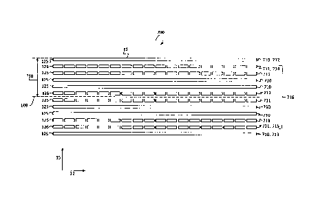
Fig. 7 shows a schematic view (not drawn to scale) of a first fur-
ther stator assembly 700 of the stator module 10 in a sectional
view in which the sectional plane is oriented perpendicularly to
the second direction 14. To the extent that no differences are de-
scribed, the first further stator assembly 700 is embodied as de-
scribed for stator assembly 100. In the first further stator assem-
bly 100, the first direction 12 is in particular oriented perpen-
dicularly to the second direction 14.
The first further stator assembly 700 comprises a total of twelve
stator layers. Six stator layers are embodied as longitudinal sta-
tor layers 710 having first coil conductors 125 and six stator lay-
ers are embodied as oblique stator layers 711 having second coil
conductors 126. The longitudinal stator layers 710 and the oblique
stator layers 711 have the same mean distance 718 from the stator
surface 11 of the first further stator assembly 700 in the third
direction 15. The longitudinal stator layers 710 and the oblique
stator layers 711 are in the third direction 15 arranged symmetri-
cally to the shared central plane 108. The topmost stator layer 712
and the lowermost stator layer 713 are embodied as longitudinal
stator layers 710 and the second topmost stator layer 714 and the
second lowermost stator layer 715 are embodied as oblique stator
layers 711.
CA 3106724 2021-03-31
34
The first further stator assembly 700 comprises inner layers 716
that are arranged within the first further stator assembly 700. The
inner layers 716 are in the third direction 15 particularly ar-
ranged between the outer layers of the first further stator assem-
bly 700, i.e. between the topmost and the lowermost stator layer
712, 713. The inner layers 716 are in the third direction 15 alter-
natingly embodied as two respectively adjacent longitudinal stator
layers 710 and as two adjacent oblique stator layers 711. In the
first further stator assembly 700, at first two oblique stator lay-
ers 711, then two longitudinal stator layers 710, then two oblique
stator layers 711, then two longitudinal stator layers 710 and then
two oblique stator layers 711 are arranged below the topmost stator
layer 712 embodied as longitudinal stator layer 710 as inner layers
716 above the lowermost stator layer 713 embodied as longitudinal
stator layer 710.
Alternative embodiments (not shown) of the first further stator as-
sembly 700 may also comprise less than twelve stator layers or more
than twelve stator layers. Particularly, alternative embodiments
(not shown) of the first further stator assembly 700 may comprise
eight stator layers, wherein between a topmost stator layer 712 em-
bodied as a longitudinal stator layer 710 and a lowermost stator
layer 713 embodied as a longitudinal stator layer 710 two oblique
stator layers 711, two longitudinal stator layers 710 and two
oblique stator layers 711 may be arranged as inner layers 716.
Fig. 8 shows a schematic sectional view of a second further stator
assembly 701 in which the sectional plane is oriented perpendicu-
larly to the second direction 14. To the extent that no differences
are described in the following, the second further stator assembly
701 is embodied as described for the first further stator assembly
700. The stator module 10 may comprise the second further stator
assembly 701 instead of the stator assembly 100.
CA 3106724 2021-03-31
35
The second further stator assembly 701 comprises a total of twelve
stator layers. Six stator layers are longitudinal stator layers 710
having first coil conductors 125 and six stator layers are oblique
stator layers 711 having second coil conductors 126. The longitudi-
nal stator layers 710 and the oblique stator layers 711 have the
same mean distance 718 from the stator surface 11 of the second
further stator assembly 701 in the third direction 15. The longitu-
dinal stator layers 710 and the oblique stator layers 711 are in
the third direction 15 arranged symmetrically with regard to the
shared central plane 108. The topmost stator layer 712 and the low-
ermost stator layer 713 are embodied as longitudinal stator layers
710 and the second topmost stator layer 714 and the second lower-
most stator layer 715 are embodied as oblique stator layers 711.
In the second further stator assembly 701, the inner layers 716 ar-
ranged between the topmost stator layer 712 and the central plane
108 are each alternatingly embodied as oblique stator layers 711
and longitudinal stator layers 710. In addition, the inner layers
716 arranged between the central plane 108 and the lowermost stator
layer 113 are each alternatingly embodied as oblique stator layers
711 and longitudinal stator layers 710. The two stator layers di-
rectly adjacent to the central plane 108 are each embodied as
oblique stator layers 711. In the second further stator assembly
701, a longitudinal stator layer 710, an oblique stator layer 711,
a longitudinal stator layer 710, an oblique stator layer 711, a
longitudinal stator layer 710, an oblique stator layer 711, an
oblique stator layer 711, a longitudinal stator layer 710, an
oblique stator layer 711, a longitudinal stator layer 710, an
oblique stator layer 711, and a longitudinal stator layer 710 are,
in this order, arranged on top of one another in the first direc-
tion 15.
Fig. 9 shows a schematic sectional view (not drawn to scale) of a
third further stator assembly 702 in which the sectional plane is
oriented perpendicularly to the second direction 14. To the extent
CA 3106724 2021-03-31
36
that no differences are described, the third further stator assem-
bly 702 is embodied as described for the first further stator as-
sembly 700. The stator module 10 may comprise the third further
stator assembly 702 instead of the stator assembly 100.
The third further stator assembly 702 comprises a total of eight
stator layers. Four stator layers are embodied as longitudinal sta-
tor layers 710 having first coil conductors 125 and four stator
layers are embodied as oblique stator layers 711 having second coil
conductors 126. The longitudinal stator layers 710 and the oblique
stator layers 711 have the same mean distance 718 from the stator
surface 11 of the third further stator assembly 702 in the third
direction 15. The longitudinal stator layers 710 and the oblique
stator layers 711 are in the third direction 15 arranged symmetri-
cally to the shared central plane 108. The topmost stator layer 712
and the lowermost stator layer 713 are embodied as longitudinal
stator layers 710.
In the third further stator assembly 702, the second topmost stator
layer 714 and the second lowermost stator layer 715 are embodied as
longitudinal stator layers 710, as well. Between the second lower-
most stator layer 715 and the second topmost stator layer 714, four
stator layers are arranged that are each embodied as oblique stator
layers 711. In the third further stator assembly 702, two longitu-
dinal stator layers 710, four oblique stator layers 711 and two
longitudinal stator layers 710 are thus arranged on top of one an-
other in the third direction 15.
In the stator assembly 100 and the first, second and third further
stator assembly 700, 701, 702, the two stator layers adjacent to
the central plane 108, i.e. the stator layer arranged above the
central plane 108 in the third direction 15 and the stator layer
arranged below the central plane 108 in the third direction 15 are
each embodied as oblique stator layers 711. In alternative embodi-
CA 3106724 2021-03-31
37
ments of the stator assemblies 100, 700, 701, 702, the stator lay-
ers adjacent to the central plane 108 may also be embodied as lon-
gitudinal stator layers 710.
Fig. 10 shows a schematic sectional view (not drawn to scale) of a
fourth further stator assembly 703, in which the sectional plane is
oriented perpendicularly to the second direction 14. To the extent
that no differences are described, the fourth further stator assem-
bly 703 is embodied as described for the first further stator as-
sembly 700. The stator module 10 may comprise the fourth further
stator assembly 703 instead of the stator assembly 100.
The fourth further stator assembly 703 comprises a total of eight
stator layers. Four stator layers are embodied as longitudinal sta-
tor layers 710 having first coil conductors 125 and four stator
layers are oblique stator layers 711 having second coil conductors
126. The longitudinal stator layers 710 and the oblique stator lay-
ers 711 have the same mean distance 718 from the stator surface 11
of the fourth further stator assembly 703 in the third direction
15. The longitudinal stator layers 710 and the oblique stator lay-
ers 711 are arranged symmetrically to the shared central plane 108
in the third direction 15. The topmost stator layer 712 and the
lowermost stator layer 713 are longitudinal stator layers 710 and
the second topmost stator layer 714 and the second lowermost stator
layer 715 are oblique stator layers 711. The inner layers 716 are
in the third direction 15 alternatingly each embodied as two adja-
cent longitudinal stator layers 710 and as two adjacent oblique
stator layers 711.
In the fourth further stator assembly 703, the stator layers adja-
cent to the central plane 108 are each embodied as longitudinal
stator layers 710. In the fourth further stator assembly 703, a
longitudinal stator layer 710, two oblique stator layers 711, two
longitudinal stator layers 710, two oblique stator layers 711 and a
CA 3106724 2021-03-31
38
longitudinal stator layer 710 are in this order arranged on top of
one another in the third direction 15.
In the stator assembly 100 and in the first, second, third and
fourth stator assembly 700, 701, 702, 703, the distance of the
shared central plane 108 from the stator surface 11 corresponds to
the mean distance 718 of the first arrangement of longitudinal sta-
tor layers 710 and to the mean distance 718 of the second arrange-
ment of oblique stator layers 711 from the stator surface 11. In
alternative embodiments of the stator assemblies 100, 700, 701,
702, 703, the distance of the central plane 108 from the stator
surface 11 and the mean distance 718 of the stator layers 710, 711
from the stator surface 11 may differ.
Fig. 11 shows a schematic sectional view (not drawn to scale) of a
fifth further stator assembly 704, in which the sectional plane is
oriented perpendicularly to the second direction 14. To the extent
that no differences are described, the fifth further stator assem-
bly 704 is embodied as described for the first further stator as-
sembly 700. The stator module 10 may comprise the fifth further
stator assembly instead of the stator assembly 100.
The fifth further stator assembly 704 comprises a total of twelve
stator layers. Six stator layers are longitudinal stator layers 710
having first coil conductors 125 and six stator layers are oblique
stator layers 711 having second coil conductors 126. The topmost
stator layer 712 and the lowermost stator layer 713 are embodied as
longitudinal stator layers 710 and the second topmost stator layer
714 and the second lowermost stator layer 715 are embodied as
oblique stator layers 711. The order of the arrangement of the lon-
gitudinal stator layers 710 and of the oblique stator layers 711 in
the third direction 15 corresponds to the order of the arrangement
of the longitudinal stator layers 710 and of the oblique stator
layers 711 in the first further stator assembly 700 according to
Fig. 7.
CA 3106724 2021-03-31
39
In the stator assembly 100 and in the first, second, third and
fourth further stator assembly 700, 701, 702, 703, all adjacent
stator layers 710, 711 are arranged at the same distance with re-
gard to each other. In the fifth further stator assembly 704, at
least one of the oblique stator layers 711 or at least one of the
longitudinal stator layers 710 has a different distance from an ad-
jacent stator layer than the other stator layers. In particular in
the fifth further stator assembly 704, the second topmost stator
layer 714 arranged below the topmost stator layer 712 has a dis-
tance from the next lower stator layer 719 that differs from the
distances between the rest of the stator layers. The distance be-
tween the second topmost stator layer 714 and the next lower stator
layer 719 may, as depicted, be larger than the distances of the
other stator layers, however, it may also be smaller. In alterna-
tive embodiments (not shown) of the fifth further stator assembly
704, a distance between two other adjacent stator layers as well as
between the second topmost stator layer 714 and the next lower sta-
tor layer 719 may differ from the distances of the rest of the ad-
jacent stator layers.
In the fifth further stator assembly 704, the first arrangement of
the longitudinal stator layers 710 and the second arrangement of
oblique stator layers 711 have a shared central plane 108. In par-
ticular, the shared central plane 108 is arranged centrally between
the longitudinal stator layer 710 lowermost in the third direction
15, i.e. the lowermost stator layer 713, and the longitudinal sta-
tor layer 710 topmost in the third direction 15, i.e. the topmost
stator layer 712, as well as centrally between the oblique stator
layer 711 lowermost in the third direction 15, i.e. the second low-
ermost stator layer 715, and the oblique stator layer 711 topmost
in the third direction 15, i.e. the second topmost stator layer
714. In the fifth further stator layer 704, the first arrangement
of the longitudinal stator layers 710 is embodied unsymmetrically
to the shared central plane 108, in particular unsymmetrically to
CA 3106724 2021-03-31
40
the central plane of the first arrangement of longitudinal stator
layers 710. Moreover, the second arrangement of oblique stator lay-
ers 711 is embodied unsymmetrically with regard to the shared cen-
tral plane 108, in particular unsymmetrically with regard to the
central plane of the second arrangement of oblique stator layers
711.
In the fifth further stator assembly 704, the longitudinal stator
layers 710 and the oblique stator layers 711 have the same mean
distance 718 from the stator surface 11 of the fifth further stator
assembly 704 in the third direction 15. The mean distance 718 is
larger than the distance between the stator surface 11 and the
shared central plane 108. In alternative embodiments (not shown) of
the fifth further stator assembly 704, the mean distance 718 may
also be smaller than the distance between the stator surface 11 and
the shared central plane 108.
In the stator assemblies 100, 700, 701, 702, 703, 704, a first to-
tal number of longitudinal stator layers 710 and a second total
number of oblique stator layers 711 are the same, i.e. the stator
assemblies 100, 700, 701, 702, 703, 704 each comprise the same num-
ber of longitudinal stator layers 710 and oblique stator layers
711. In alternative embodiments of the stator assemblies 100, 700,
701, 702, 703, 704, the first total number and the second total
number may also differ and the stator assemblies 100, 700, 701,
702, 703, 704 may comprise more longitudinal stator layers 710 than
oblique stator layers 711, or vice versa.
Fig. 12 shows a schematic sectional view of a sixth further stator
assembly 705 of the stator module 10, in which the sectional plane
is oriented perpendicularly to the second direction 14. To the ex-
tent that no differences are described in the following, the sixth
further stator assembly 705 is embodied as described for the first
further stator assembly 700. The stator module 10 may comprise the
CA 3106724 2021-03-31
41
sixth further stator assembly 705 instead of the stator assembly
100.
The longitudinal stator layers 710 and the oblique stator layers
711 in the third direction 15 comprise the same mean distance 718
from the stator surface 11 of the sixth further stator assembly
705. The longitudinal stator layers 710 and the oblique stator lay-
ers 711 are in the third direction 15 arranged symmetrically to the
shared central plane 108. In the sixth further stator assembly 705,
two oblique stator layers 711 and two longitudinal stator layers
710 are respectively arranged on top of one another in an alternat-
ing manner in the third direction 15. In the sixth further stator
assembly 705, this includes the outer layers as well as the inner
layers 716. In particular, in the sixth further stator assembly 705
the topmost stator layer 712 and the lowermost stator layer 713 as
well as the second topmost stator layer 714 and the second lower-
most stator layer 715 are embodied as oblique stator layers 711.
In the sixth further stator assembly 705, the first total number of
longitudinal stator layers 710 and the second total number of
oblique stator layers 711 are not equal, in particular the first
total number is smaller than the second total number. The sixth
further stator assembly 705 in total comprises ten stator layers.
Six stator layers are embodied as oblique stator layers 711 and
four stator layers are embodied as longitudinal stator layers 710.
In alternative embodiments (not shown) of the sixth further stator
assembly 705, the first total number may be larger than the second
total number.
In the sixth further stator assembly 705, the stator layers adja-
cent to the central plane 108 are each embodied as oblique stator
layers 711. In the sixth further stator assembly 705, two oblique
stator layers 711, two longitudinal stator layers 710, two oblique
stator layers 722, two longitudinal stator layers 710 and two
CA 3106724 2021-03-31
42
oblique stator layer 711 are arranged on top of one another in that
order.
In the sixth further stator assembly 705, the stator layers each
have the same distance from one another. The shared central plane
108 is arranged centrally between the topmost stator layer 712 and
the lowermost stator layer 713. The distance of the shared central
plane 108 from the stator surface 11 thus also corresponds to the
mean distance 718 of the longitudinal stator layer 710 and the
oblique stator layer 711 from the stator surface 11.
The stator assemblies 100, 700, 701, 702, 703, 704, 705 may com-
prise a plurality of two-layer circuit boards arranged on top of
one another. The two-layer circuit boards may each comprise a first
and a second conductor-path layer which is arranged at a first side
and at a second side of the circuit board and between which an iso-
lating intermediate layer is arranged. The first conductor-path
layer may be connected to the second conductor-path layer in an
electrically conductive manner via through-contacts which are
guided through the isolating intermediate layer. The through-con-
tacts may e.g. be conductively coated through-holes in the interme-
diate layer. In this context, the through-contacts can only extend
over the very circuit board on which the conductor-path layers con-
nected via the relevant through-contacts are arranged; however,
they cannot extend over the entire stator assembly 100, 700, 701,
702, 703, 704, 705. Such through-contacts of a circuit board con-
sisting of a plurality of two-layer circuit boards are also re-
ferred to as buried vias.
The two-layer circuit boards may be arranged on top of one another
and be glued or pressed to one another so that the stator assembly
100, 700, 701, 702, 703, 704, 705 altogether comprises a multi-
layer circuit board having an even number of conductor-path layers.
CA 3106724 2021-03-31
43
Fig. 13 shows a further schematic sectional view (not drawn to
scale) of the first further stator assembly 700, wherein the sec-
tional plane is perpendicular to the second direction 14.
The first further stator assembly 700 comprises a first carrier
plate 720 and a second carrier plate 730. To the extent that no
differences are described, the second carrier plate 730 is embodied
as described for the first carrier plate 720.
The first carrier plate 720 has a plate shape in the first direc-
tion 12 and in the second direction 14, in particular a plate shape
extending in the first and second direction 12, 14. The first car-
rier plate 720 extends in the first direction 12 and in the second
direction 14 and comprises a lower extension in the third direction
15 than in the first direction 12 and in the second direction 14.
In the first direction 12, the first carrier plate 720 extends be-
tween the side faces 32 of the first further stator assembly 700
oriented along the second direction 14. In the second direction 14,
the first carrier plate 720 extends between the side faces 32 of
the first further stator assembly 700 oriented along the first di-
rection 12.
The first carrier plate 720 has a two-layer embodiment, i.e. it
comprises two stator layers of the first further stator assembly
700. The first carrier plate 720 comprises a first side 723 and a
second side 724 opposite to the first side 723 in the third direc-
tion 15. On the first side 723 of the first carrier plate 720, a
longitudinal stator layer 710 of the first further stator assembly
700 referred to as first longitudinal stator layer 721 is arranged
with first coil conductors 125. On the second side 724 of the first.
carrier plate 720, an oblique stator layer 711 of the first further
stator assembly 700 referred to as first oblique stator layer 722
is arranged with second coil conductors 126. The first side 723 of
the first carrier plate 720 and the second side 724 of the first
CA 3106724 2021-03-31
44
carrier plate 720 are each embodied in a plane manner and arranged
in parallel to each other.
The first carrier plate 720 comprises an electrically isolating ma-
terial, e.g. a ceramic material, a plastic material or a glass-fi-
ber-reinforced plastic material. The first longitudinal stator
layer 721 having first coil conductors 125 and the first oblique
stator layer 722 having second coil conductors 126 are embodied as
flat and electrically conductive layers, e.g. metallic layers, in
the third direction 15.
The first carrier plate 720 may be a circuit board, in particular a
printed circuit board, and the first longitudinal stator layer 721
and the first oblique stator layer 722 may be embodied as conduc-
tor-path layers of the circuit board. The first coil conductor 125
of the first longitudinal stator layer 721 and the second coil con-
ductor 126 of the first oblique stator layer 722 may be embodied as
conductor strips with an elongated extension having a thickness be-
tween lOpm and 500pm on the sides 723, 724 or on the layers of the
first carrier plate 720, in particular the conductor strips may
have a thickness between 50pm and 250pm. The first coil conductors
125 of the first longitudinal stator layer 721 and the second coil
conductors 126 of the second oblique stator layer 722 may also be
embodied as metal strips or metal wires.
The second carrier plate 730 is embodied as described for the first
carrier plate 720. In particular, the second carrier plate 730 com-
prises a first side 733 and a second side 734 opposite to the first
side 733 of the second carrier plate 730 in the third direction 15.
On the first side 733 of the second carrier plate 730, a longitudi-
nal stator layer 710 referred to as second longitudinal stator
layer 731 having first coil conductors 125 is arranged and on the
second side 734 of the second carrier plate 733, an oblique stator
layer 711 referred to as second oblique stator layer 732 having
second coil conductors 126 is arranged. In analogy to the first
CA 3106724 2021-03-31
45
carrier plate 720, the second carrier plate 730 may be embodied as
a circuit board, in particular as a printed circuit board, and the
second longitudinal stator layer 731 and the first oblique stator
layer 732 may be embodied as conductor-path layers of the circuit
board.
The first carrier plate 720 is aligned in such a way that the first
side 723 of the first carrier plate is in the third direction 15
located above the second side 724 of the first carrier plate 720.
Thus, the first side 723 of the first carrier plate 720 forms the
upper side of the first carrier plate 720 in the third direction 15
and the second side 724 of the first carrier plate 720 forms the
bottom surface of the first carrier plate 720 in the third direc-
tion 15. The second carrier plate 730 is aligned in such a way that
the first side 733 of the second carrier plate 730 is in the third
direction 15 below the second side 734 of the second carrier plate
730. Thus, the first side 733 of the second carrier plate 730 forms
the bottom surface of the second carrier plate 730 in the third di-
rection 15 and the second side 734 of the second carrier plate 730
forms the upper side of the second carrier plate 730 in the third
direction 15.
The first carrier plate 720 and the second carrier plate 730 of the
first further stator assembly 700 are arranged side-by-side in the
third direction 15. The first carrier plate 720 and the second car-
rier plate 730 are aligned in parallel to each other. The first
carrier plate 720 is arranged above the second carrier plate 730 in
the third direction. In particular, the second side 724 of the
first carrier plate 720 is arranged facing the second side 734 of
the second carrier plate 730. The first side 723 of the first car-
rier plate 720 in the third direction 15 forms an upper side 101 of
the first further stator assembly 700.
CA 3106724 2021-03-31
46
In the first further stator assembly 700, the first longitudinal
stator layer 721 forms the first stator layer 104 of the first fur-
ther stator assembly 700. The first oblique stator layer 722 forms
the second stator layer 105, the second oblique stator layer 732
forms the third stator layer 106 and the second longitudinal stator
layer 731 forms the fourth stator layer 107 of the first further
stator assembly 700.
An isolating layer 728 is arranged between the first carrier plate
720 and the second carrier plate 730. The isolating layer 728 is
embodied in an electrically isolating manner. The isolating layer
728 may e.g. comprise plastic or a ceramic material. The isolating
layer 728 may in the first direction 12 extend between the side
faces 32 of the first further stator assembly 700 running along the
second direction 14 and in the second direction 14 between the side
faces 32 of the first further stator assembly 700 running along the
first direction 12. The isolating layer 728 and the carrier plate
720, 730 may have the same thickness in the third direction 15. The
thickness of the carrier plate 720, 730 and of the isolating layer
728 may in the third direction e.g. be between 35pm and 200pm, in
particular between 50pm and 100pm, in particular amount to 75pm.
However, the isolating layer 728 may also have a lower or larger
thickness in the third direction 15 than the carrier plates 720,
730.
The isolating layer 728 is firmly mechanically connected to the
first carrier plate 720 and to the second carrier plate 730. The
isolating layer 728 may for example be glued to the carrier plates
720, 730. Alternatively or additionally, a connecting element may
extend through the first further stator assembly 700 in the third
direction 15 and mechanically connect the carrier plates 720, 730
and the isolating layer 728. The connecting element may for example
extend from the upper side 101 of the first further stator assembly
700 to the bottom surface 102 of the stator assembly 700. The con-
necting element may for example extend from the first side 723 of
CA 3106724 2021-03-31
47
the first carrier plate 720 to the first side 733 of the second
carrier plate 730. The connecting element may for example be embod-
ied as a press-fit connector. Apart from the connecting element,
the first further stator assembly 700 may comprise further connect-
ing elements of identical embodiment.
Apart from the first and second carrier plate 720, 730, the first
further stator assembly 700 comprises four further carrier plates
750. To the extent that no differences are described, the further
carrier plates 750 are embodied and arranged as described for the
first and second carrier plate 720, 730. In particular, the further
carrier plates 750 each comprise a first side 753 having a longitu-
dinal stator layer 710 and a second side 754 having an oblique sta-
tor layer 711. The carrier plates 720, 730, 750 of the first fur-
ther stator assembly 700 are in the third direction 15 arranged on
top of one another and in parallel with regard to one another. In
this context, the first sides 723, 733, 753 and the second sides
724, 734, 754 of adjacently arranged carrier plates 720, 730, 750
are in the third direction 15 each alternatingly arranged facing
each other.
In the first further stator assembly 700, the first carrier plate
720 is arranged as the topmost carrier plate in the third direction
15 above the rest of the carrier plates 730, 750. The first longi-
tudinal stator layers 721 forms the topmost stator layer 712 and
the first oblique stator layer 722 forms the second topmost stator
layer 714 of the first further stator assembly 700. The first side
723 of the first carrier plate 720 forms an upper side 101 of the
first further stator assembly 700.
In the third direction 15 below the first carrier plate 720, the
second carrier plate 730, a first further carrier plate 756, a sec-
ond further carrier plate 757, a third further carrier plate 758
and a fourth further carrier plate 759 are arranged one after the
CA 3106724 2021-03-31
48
other. The first side 733 of the second carrier plate 730 is ar-
ranged facing the first side 753 of the first further carrier plate
756, the second side 754 of the first further carrier plate 756 is
arranged facing the second side 754 of the second further carrier
plate 575, the first side 753 of the second further carrier plate
757 is arranged facing the first side 753 of the third further car-
rier plate 758 and the second side 754 of the third further carrier
plate 758 is arranged facing the second side 754 of the fourth fur-
ther carrier plate 759. The first side 753 of the fourth further
carrier plate 759 forms the bottom surface 102 of the first further
stator assembly 700.
An isolating layer 728 is respectively arranged between the carrier
plates 720, 730, 750, which is embodied as the isolating layer 728
arranged between the first and second carrier plate 720, 730.
The first further stator assembly 700 in total comprises a multi-
layer stator-layer arrangement with an even number of stator lay-
ers. The first further stator assembly 700 in particular comprises
a twelve-layer stator-layer arrangement. The first further stator
assembly 700 comprises a plurality of two-layer carrier plates 720,
730, 750 arranged on top of one another in the third direction 15.
In particular, the first further stator assembly 700 comprises six
two-layer carrier plates 720, 730, 750 arranged on top of one an-
other in the third direction 15.
In the first further stator assembly 700, an oblique stator layer
711 is in the third direction 15 arranged beside each longitudinal
stator layer 710 and a longitudinal stator layer 710 beside each
oblique stator layer 711 inside of the stator assembly 700, i.e.
with the exception of the topmost stator layer 712 and the lower-
most stator layer 713. Thereby, each longitudinal stator layer 710
is arranged on the first side 723, 733, 753 and each adjacently ar-
ranged oblique stator layer 711 on the second side 724, 734, 754 of
CA 3106724 2021-03-31
49
the respective two-layer carrier plates 720, 730, 750. In particu-
lar, the first further stator assembly 700 exclusively comprises
two-layer carrier plates 720, 730, 750, respectively, on the first
side 723, 733, 753 of which a longitudinal stator layer 710 and on
the second side 724, 734, 754 of which an oblique stator layer 711
is arranged.
In the stator assembly 100, the first further stator assembly 700,
the second further stator assembly 701, the fourth further stator
assembly 703 and the fifth further stator assembly 704, at least an
oblique stator layer 711 is in the third direction 15 arranged be-
side each longitudinal stator layer 710. In this context, each lon-
gitudinal stator layer 710 may be embodied as the first conductor-
path layer and the adjacently arranged oblique stator layer 711 as
the second conductor-path layer of a two-layer circuit board. Par-
ticularly, the stator assembly 100 and the first, second, fourth
and fifth further stator assembly 700, 701, 703, 704 may each ex-
clusively comprise two-layer circuit boards, the first conductor-
path layer of which is embodied as an oblique stator layer 710 and
the second conductor-path layer of which is embodied as an oblique
stator layer 711. The longitudinal stator layers 710 and the
oblique stator layers 711 of the individual circuit boards may then
be connected to each other in an electrically conductive manner by
means of through-contacts, e.g. buried vias, embodied exclusively
on the relevant circuit board.
In the stator assemblies 100, 700, 701, 702, 703, 704, 705, the
first coil conductors 125 are embodied with an elongated extension
in the first direction 12 and as first conductor strips arranged
side-by-side in the second direction 14. In addition, the second
coil conductors 126 are embodied with an elongated extension in the
second direction 12 and as second conductor strips arranged side-
by-side in the first direction 12. In alternative embodiments (not
shown), the stator assemblies 100, 700, 701, 702, 703, 704, 705,
the first coil conductors 125 and/or the second coil conductors 126
CA 3106724 2021-03-31
50
may be embodied as wires or wound coils. First coil conductors 125
embodied in such a way may, in analogy to the coil conductors 125
embodied as conductor strips, have an elongated extension in the
first direction 12 and a side-by-side arrangement in the second di-
rection 14. Likewise, second coil conductors 126 embodied in such a
say may, in analogy to the coil conductors 126 embodied as conduc-
tor strips, have an elongate extension in the second direction 14
and a side-by-side arrangement in the first direction 12.
In terms of the present invention, the term "stator assembly"
merely refers to the arrangement of the longitudinal stator layers
710 and of the oblique stator layer 711 in the third direction 15
and does not implicitly suggest that the longitudinal stator layers
710 and/or the oblique stator layers 711 necessarily have to be me-
chanically connected to each other. This may, however, be the case
with the stator assemblies 100, 700, 701, 702, 703, 704, 705 embod-
ied as circuit boards, in particular as printed circuit boards. Al-
ternatively, the longitudinal stator layers 710 and/or the oblique
stator layers 711 may e.g. be embodied as separate plates arranged
on top of one another in the third direction 15 and connected to
each other by means of connecting means.
CA 3106724 2021-03-31
51
Reference list
1 planar drive system
8 upper side
9 bottom side
stator module
11 stator surface
12 first direction
14 second direction
10 15 third direction
18 connecting line
19 module housing
30 outer edge of stator surface
32 side face of the stator assembly
34 side face of the module housing
36 side face of the stator module
100 stator assembly
101 upper side
102 bottom side
104 first stator layer
105 second stator layer
106 third stator layer
107 fourth stator layer
108 central plane
110 first stator sector
112 second stator sector
113 third stator sector
114 fourth stator sector
120 first stator segments
121 second stator segments
125 first coil conductor
126 second coil conductor
200 rotor
201 magnetic arrangement
206 first rotor direction
CA 3106724 2021-03-31
52
208 second rotor direction
210 first magnetic unit
211 first drive magnet
220 second magnetic unit
221 second drive magnet
230 third magnetic unit
240 fourth magnetic unit
700 first further stator assembly
701 second further stator assembly
702 third further stator assembly
703 fourth further stator assembly
704 fifth further stator assembly
705 sixth further stator assembly
710 longitudinal stator layer
711 oblique stator layer
712 topmost stator layer
713 lowermost stator layer
714 second topmost stator layer
715 second lowermost stator layer
716 interior layers
718 mean distance
719 next lowest stator layer
720 first carrier plate
721 first longitudinal stator layer
722 first oblique stator layer
723 first side of first carrier plate
724 second side of first carrier plate
728 isolating layer
730 second carrier plate
731 second longitudinal stator layer
732 second oblique stator layer
733 first side of second carrier plate
734 second side of second carrier plate
750 further carrier plate
753 first side of further carrier plate
CA 3106724 2021-03-31
53
754 second side of further carrier plate
756 first further carrier plate
757 second further carrier plate
758 third further carrier plate
759 fourth further carrier plate
CA 3106724 2021-03-31