Note: Descriptions are shown in the official language in which they were submitted.
CA 03107509 2021-01-22
WO 2020/023914
PCT/US2019/043748
LAST STEP INDICATOR FOR LADDERS AND LADDERS INCORPORATING SAME
CROSS-REFERENCE TO RELATED APPLICATIONS
[0001] This
application claims the benefit of U.S. Provisional Patent Application
No. 62/711,266, filed on July 27, 2018, the disclosure of which is
incorporated by reference
herein in its entirety.
BACKGROUND
[0002] Ladders
are conventionally utilized to provide a user thereof with improved
access to elevated locations that might otherwise be inaccessible. Ladders
come in many
shapes and sizes, such as straight ladders, straight extension ladders,
stepladders, and
combination step and extension ladders. So-called combination ladders may
incorporate, in a
single ladder, many of the benefits of various ladder designs.
[0003] Ladders
known as step ladders, sometimes referred to as A-frame ladders,
are self-supporting ladders, meaning that they do not need to be leaned
against a wall, pole or
other structure for stability. Rather, step ladders may be positioned on a
floor (or other similar
surface) such that at least three feet of the ladder, and conventionally four
feet, provide a stable
support structure for a user to climb upon, even in an open space (e.g.,
outside or in the middle
of a room) without a wall, roof, pole or other type of structure being
necessary for the stability
of the ladder. Conventional step ladders may include a first rail assembly
coupled with a top
cap and a second rail assembly coupled with the top cap. One of the rail
assemblies
conventionally includes a plurality of rungs that are evenly spaced between
the supporting
surface (e.g., the floor or ground) and the top cap.
[0004]
Regardless of the type of ladder being employed, using a ladder can present
various risks to the user. For example, one potential hazard exists where a
user is distracted or
is not paying attention and loses track of which rung they are currently
standing on ¨
particularly when they are descending the ladder. In such a case, a user may
think, for example,
that their next "step" downward will place them on the ground at the bottom of
the ladder when,
in reality, there is still one more step for them to descend prior to reaching
the ground. This
misperception can result in the user stumbling on, or even missing completely,
the lowest rung
of the ladder. There is a continuing desire in the industry to provide ladders
that reduce the
risk of accident and provide improved safety and stability to a user thereof.
1
CA 03107509 2021-01-22
WO 2020/023914
PCT/US2019/043748
SUMMARY OF DISCLOSURE
[0005] Ladders
and rungs assemblies for ladders are provided herein. In
accordance with one embodiment of the present disclosure a ladder comprises a
first assembly
comprising a pair of spaced apart rails and a rung assembly coupled between
the first pair of
rails. The rung assembly comprises: a base member, a displaceable member
disposed over a
portion of the base member and configured to be displaced from a first
position to a second
position relative to the base member, and at least
one alert mechanism associated with the
displaceable member and configured to provide an audible alert when the
displaceable member
is displaced from the first position to the second position, wherein the at
least one alert
mechanism is directly coupled with one rail of the pair of spaced apart rails.
[0006] In
accordance with one embodiment, the displaceable member is disposed
between the at least one alert mechanism and the base member.
[0007] In
accordance with one embodiment, the at least one alert mechanism
includes a first alert mechanism coupled with the first rail and a second
alert mechanism
directly coupled with a second rail of the pair of space apart rails.
[0008] In
accordance with one embodiment, the ladder further comprises a
plurality of additional rungs extending between and coupled to the pair of
spaced apart rails.
[0009] In
accordance with one embodiment, the rung assembly is positioned to act
as a lowermost rung of the ladder.
[0010] In
accordance with one embodiment, the displaceable member includes an
upper tread portion and a rear wall and a front wall.
[0011] In
accordance with one embodiment, the at least one alert mechanism
includes a pin, a collar slidably disposed about the pin, and a detent
mechanism configured to
hold the collar at a specified position on the pin until a force of a
specified magnitude is applied
to the collar.
[0012] In
accordance with one embodiment, the displaceable member is directly
coupled with a lower portion of the pin.
[0013] In
accordance with one embodiment, the at least one alert mechanism is
positioned and configured so that the detent mechanism releases the collar
when the
displaceable mechanism is in the first position.
[0014] In
accordance with one embodiment, the ladder further comprises a pair of
adjustable legs including a first leg movably coupled with the first rail and
a second leg
movably coupled with a second rail of the pair of spaced apart rails.
2
CA 03107509 2021-01-22
WO 2020/023914
PCT/US2019/043748
[0015] In
accordance with another embodiment of the present disclosure another
ladder comprises a first assembly comprising a pair of spaced apart rails and
a rung assembly
coupled between the first pair of rails. The rung assembly comprises: a base
member and a
displaceable member disposed over a portion of the base member and configured
to be
displaced from a first position to a second position relative to the base
member, wherein the
displaceable member is not in contact with the base member when in the first
position.
[0016] In
accordance with one embodiment, the ladder further comprises at least
one alert mechanism associated with the displaceable member and configured to
provide an
audible alert when the displaceable member is displaced from the first
position to the second
position
[0017] In
accordance with one embodiment, the at least one alert mechanism is
directly coupled with one rail of the pair of spaced apart rails.
[0018] In
accordance with one embodiment, the displaceable member is disposed
between the at least one alert mechanism and the base member.
[0019] In
accordance with one embodiment, the at least one alert mechanism
includes a first alert mechanism coupled with the first rail and a second
alert mechanism
directly coupled with a second rail of the pair of space apart rails.
[0020] In
accordance with one embodiment, the rung assembly is positioned to act
as a lowermost rung of the ladder.
[0021] In
accordance with one embodiment, the at least one alert mechanism
includes a pin, a collar slidably disposed about the pin, and a detent
mechanism configured to
hold the collar at a specified position on the pin until a force of a
specified magnitude is applied
to the collar.
[0022] In
accordance with one embodiment, the displaceable member is directly
coupled with a lower portion of the pin.
[0023] In
accordance with one embodiment, the at least one alert mechanism is
positioned and configured so that the detent mechanism releases the collar
when the
displaceable mechanism is in the first position.
[0024] In
accordance with one embodiment, wherein the ladder further comprises
a pair of adjustable legs including a first leg movably coupled with the first
rail and a second
leg movably coupled with a second rail of the pair of spaced apart rails.
[0025]
Features, elements or aspects of one embodiment may be combined with
features, elements or aspects of other embodiments without limitation.
3
CA 03107509 2021-01-22
WO 2020/023914
PCT/US2019/043748
BRIEF DESCRIPTION OF THE DRAWINGS
[0026] The foregoing and other advantages of the disclosure will become
apparent
upon reading the following detailed description and upon reference to the
drawings in which:
[0027] FIG. 1 is a perspective view of a step ladder according to an
embodiment
of the present disclosure;
[0028] FIG. 2 is a perspective view of a rung assembly according to an
embodiment of the present disclosure;
[0029] FIG. 3 is a perspective view of the rung assembly of FIG. 2,
showing a
hidden portion of the rung assembly;
[0030] FIG. 4 is a side view of the rung assembly of FIG. 2 while in a
first state;
[0031] FIG. 5 is a side view of the rung assembly if FIG. 2 while in a
second state;
[0032] FIG. 6 is a side view of an audible alert mechanism in a first
state as may
be used in a rung assembly according to an embodiment of the present
disclosure;
[0033] FIG. 7 is a side view of the mechanism shown in FIG. 6 while in
a second
state;
[0034] FIG. 8 is a side view of the mechanism shown in FIG. 6 while in
a third
state;
[0035] FIG. 9 is an exploded view of the mechanism shown in FIG 6;
[0036] FIG. 10 is a top perspective view of a rung assembly according
to another
embodiment of the present disclosure;
[0037] FIG. 11 is a bottom perspective view of the rung assembly shown
in FIG.
10;
[0038] FIG. 12 is a side view of the rung assembly shown in FIG. 10;
[0039] FIG. 13 is a top perspective view of a base member of the rung
assembly
shown in FIG. 10;
[0040] FIG. 14 is a perspective view of a rung assembly according to
another
embodiment of the present disclosure;
[0041] FIG. 15 is a side view of the rung assembly shown in FIG. 14;
[0042] FIG. 16 is a front view of the rung assembly shown in FIG. 14;
[0043] FIG. 17 is a perspective view of another ladder according to an
embodiment
of the present disclosure;
[0044] FIG. 18 depicts a portion of the ladder shown in FIG. 17
including a rung
assembly according to another embodiment of the present disclosure;
4
CA 03107509 2021-01-22
WO 2020/023914
PCT/US2019/043748
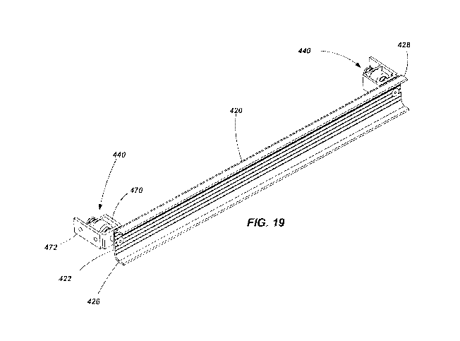
[0045] FIG. 19
is a bottom perspective view of various components of the rung
assembly shown in FIG. 18;
[0046] FIG. 20
is an enlarged view of a portion of the components shown in FIG.
18;
[0047] FIGS. 21
and 22 are sections views of certain components of the rung
assembly shown in FIG. 18 while in an unactuated and actuated state,
respectively.
DESCRIPTION OF THE EMBODIMENTS
[0048] Various
embodiments of ladders, ladder components, assemblies and
mechanisms are described herein. The described embodiments are not mutually
exclusive of
each other. Rather, various features of one described embodiment may be used
in conjunction
with features of other describe embodiments without limitation.
[0049]
Referring initially to FIG. 1 a stepladder 100 is shown in accordance with
an embodiment of the present disclosure. The stepladder 100 includes a first
assembly 102
having a pair of spaced apart rails 104 and a plurality of rungs 106 extending
between, and
coupled to, the rails 104. The spaced apart rungs 106 are substantially
parallel to one another
and are configured to be substantially level when the stepladder 100 is in an
orientation for
intended use, so that they may be used as "steps" for a user to ascend the
stepladder 100 as will
be appreciated by those of ordinary skill in the art. In the specific
embodiment shown in FIG.
1, the lowermost rung comprises a rung assembly 106A as will be described in
further detail
below. In other embodiments, other rungs (e.g., second lowest rung, top rung,
or all rungs)
may alternatively, or additionally, comprise a rung assembly if desired.
[0050] The
stepladder 100 also includes a second assembly 108 having a pair of
spaced apart rails 110. The second assembly 108 need not include a plurality
of rungs between
the spaced apart rails 110. Rather, bracing or other structural components may
be used to
provide a desired level of rigidity and strength to the spaced apart rails
110. However, in some
embodiments, the second assembly 108 may include rungs configured generally
similar to
those associated with the first assembly 102. The second assembly 108, thus,
may be used to
help support the stepladder 100 when in an intended operational state, such as
generally
depicted in FIG. 1.
[0051] The
first and second assemblies 102 and 108 may be formed of a variety of
materials and using a variety of manufacturing techniques. For example, in one
embodiment,
the rails 104 and 110 may be formed of a composite material, such as
fiberglass, while the
CA 03107509 2021-01-22
WO 2020/023914
PCT/US2019/043748
rungs and other structural components may be formed of aluminum or an aluminum
alloy. In
other embodiments, the assemblies 102 and 108 (and their various components)
may be formed
of other materials including other composites, plastics, polymers, metals,
metal alloys or
combinations of such materials.
[0052] A top
cap 112 is coupled to a portion of the first assembly 102 and a portion
of the second assembly. For example, the top cap 112 may be pivotally coupled
to an upper
end of the each rail 104 of the first assembly 102 along a common axis. In the
embodiment
shown in FIG. 1, the top cap 112 is also pivotally coupled to an upper end of
each rail 110 of
the second assembly 108 along another common axis. It is noted that the use of
the term "upper
end" merely refers to a relative position of the described components when the
stepladder 100
is in an orientation of intended use orientation.
[0053] In one
embodiment, the top cap 112 may simply be a structural component
configured to facilitate relative coupling of the first and second assemblies
102 and 108. In
other embodiments, the top cap may include features that enable it to be used
as a tray or a tool
holder. Thus, the top cap 112 may be used to organize a user's tools, supplies
and other
resources while working on the stepladder 100. For example, such a top cap is
described in
U.S. Patent No. 8,186, 481 issued May 29, 2012 and entitled LADDERS, LADDER
COMPONENTS AND RELATED METHODS, the disclosure of which is incorporated by
reference herein in its entirety. It is noted that, for safety purposes, the
top cap 112 is not
conventionally configured as a "rung" or a "step" and may not necessarily be
designed to
support a user's full weight. As with other components of the stepladder 100,
the top cap 112
may be formed from a variety of materials. In one embodiment, the top cap 112
may be formed
from a plastic material that is molded into a desired size and shape.
[0054] The
stepladder 100 may additionally include a plurality of feet 114 (one
associated with each rail) configured to engage a supporting surface such as
the ground. The
feet 114 may be configured in a variety of manners based on, for example, the
type of
environment in which the ladder is anticipated to be used. For example, the
feet may be formed
of a plastic or polymer material and can be configured with a plurality of
ridges, knobs or other
features configured to provided increased friction between the ladder and a
relatively rigid
supporting surface (e.g., concrete, tile or wood). On the other hand, the feet
114 may be
configured with barbs or other sharp protrusions configured to dig into a
relatively softer
supporting surface (e.g., dirt or grass).
[0055] A pair
of hinged braces, referred to herein as spreaders 120, are used to
maintain a desired angle between the first and second assemblies 102 and 108
when the
6
CA 03107509 2021-01-22
WO 2020/023914
PCT/US2019/043748
stepladder 100 is in a deployed or useable state. The hinged nature of such
spreaders 120 helps
to enable the first and second assemblies 102 and 108 to collapse into a
stored state and then
help lock the assemblies 102 and 108 in position relative to one another when
in a deployed or
useable state. It is noted that the spreaders 120 are not configured as rungs
or platforms, or
otherwise configured to support a user standing thereon. Rather, the spreaders
120 are simply
configured to structurally maintain the ladder 100 in a deployed position
while enabling the
rail assemblies to be selectively collapsed relative to each other for storage
and transportation
of the ladder 100.
[0056] An
example of a ladder having both rail assemblies directly pivotally
coupled with the top cap 112 is set forth in U.S. Patent No. 8,701,831
(Application No.
12/716,126 entitled STEPLADDERS AND RELATED METHODS filed March 2, 2010), the
disclosure of which is incorporated by reference herein in its entirety. It is
noted, as described
with respect to other embodiments below, that both rail assemblies need not be
pivotally
coupled with the top cap. Additionally, in some embodiments, the second
assembly 108 may
include only a single rail if desired. Other examples of stepladders and top
caps are described
in U.S. Patent Application No. 14/496,987 entitled STEP LADDERS, COMPONENTS
FOR
STEP LADDERS AND RELATED METHODS, filed Sept. 25, 2014, claiming priority to
U.S.
Provisional Application 62/045,979, filed September 4, 2014, entitled STEP
LADDERS, the
disclosures of which are incorporated by reference herein in their entireties.
[0057]
Referring now to FIGS. 2-5, a rung assembly 106A is shown in accordance
with an embodiment of the disclosure. The rung assembly 106A includes a base
member 140
that is configured for substantially rigid coupling with the rails 104 of the
first assembly 102
of a ladder 100. In the embodiment shown, the base member 140 includes a front
wall 142, a
rear wall 144, and an upper wall 146 extending between and coupled with the
front and rear
walls 142 and 144. In the embodiment shown, the various walls 142, 144 and 146
are formed
as an integral unit (e.g., welding, brazing, adhesive, mechanical fasteners,
etc.). The upper wall
146 may or may not include traction features (e.g., ridges and grooves) such
as are often found
in conventional ladder rungs.
[0058] A groove
148 is formed at, and extends along, the front edge of the upper
wall 146. The groove 148 may be positioned directly between the upper wall 146
and the front
wall 142. In other embodiments, the groove 148 may be formed wholly in the
upper wall 146
or wholly in the front wall 142. In other embodiments, rather than a single
continuous groove
148 that extends substantially the entire width (i.e., extending between the
rails 104 when
attached to a ladder) of the base member 140, one or more grooves of shorter
dimension may
7
CA 03107509 2021-01-22
WO 2020/023914
PCT/US2019/043748
extend partially along the width of the base member 140. In yet other
embodiments, it is noted
that the groove 148 could be located along the rear edge of the upper wall
146, reversing the
pivoting action of the displaceable member 150 which is described further
below.
[0059] As just
noted, the assembly 106A further includes a displaceable member
150 that is coupled with the base member 140. In the embodiment shown in FIGS.
2-5, the
displaceable member includes an upper wall or tread portion 152, which may
include one or
more traction features 154 (e.g., ridges and grooves). The displaceable member
150 may
include a rear wall 156 that is configured to extend to, or beyond, the
juncture of the rear wall
144 and upper wall 146 of the base member 140. During actuation of the
assembly 106A, the
rear wall 156 of the displaceable member may help to prevent the inadvertent
pinching of a
user's body, the catching of clothing or the entrance of foreign objects
between the displaceable
member 150 and the base 140.
[0060] The
displaceable member 150 may also include a pivot member 158 (or
multiple pivot members) disposed within the groove 148 of the base member 140.
The pivot
member 158 may include, for example, an elongated member having a portion
thereof that is
substantially cylindrical, the pivot member 158 being configured to
substantially conform in
size and shape with the groove 148. As seen by comparing FIGS. 4 and 5, the
pivot member
158 enables pivoting of the displaceable member 150 relative to the fixed base
140 about an
axis extending generally along the front edge of the rung assembly 106A (e.g.,
along or adjacent
an edge where the front wall 142 meets the upper wall 146 of the base 140) and
extending
between the rails 104 of the ladder 100. The "unactuated" or "normal" state of
the rung
assembly is shown in FIG. 4, with the displaceable member 150 positioned so
that its tread
portion or upper wall 152 is at an acute angle relative to the upper wall 146
of the base member
140. As shown in FIG. 5, when actuated (e.g., when a user is standing on the
rung assembly),
the upper wall 154 of the displaceable member is pivoted such that it is
positioned against and
substantially parallel with the upper wall 146 of the base member 140.
[0061] The rung
assembly 106A further includes one or more alert mechanisms
170 that, when actuated by displacement of the displaceable member 150 a
desired distance
(e.g., from the position in FIG. 4 to the position in FIG. 5), provides an
alert to the user (e.g.,
by audible noise) informing them that they have stepped on the rung assembly
106A. Thus,
for example, when the rung assembly 106A is placed as the lowermost rung of a
ladder (e.g.,
as shown in FIG. 1), the alert mechanism 170 provides a user with information,
as they descend,
that they have reached the lowermost rung and that their next step downward
will be to the
ground or other surface supporting the ladder 100.
8
CA 03107509 2021-01-22
WO 2020/023914
PCT/US2019/043748
[0062]
Referring to FIGS. 6-9, the alert mechanism 170 is shown in accordance
with an embodiment of the present disclosure. The alert mechanism 170 includes
a housing
member or a bracket 180 having flange portions of 181 for coupling with the
upper wall 146
of the base member 140. The bracket 180 includes two walls 182 and 184, each
having an
opening 186 and 188 formed therein. A pin member 190 extends through the
openings 186
and 188. The pin member 190 includes a shoulder 192 formed along an upper
portion thereof
and sized to be wider than the opening 186 formed in the upper wall 182. The
shoulder 192
abuts a biasing member 194 (e.g., a coiled spring or other member) positioned
about the pin
member 190 between the upper wall 184 and the shoulder 192. The shoulder 192
cooperates
with the biasing member 194 to retain the pin member 186 within the bracket
180 and also
biases the pin 190 upwards relative to the bracket 180.
[0063] A
retainer 196 may be coupled to a lower end of the pin member 190 (e.g.,
a c-clip or snap ring disposed in a groove 198 formed in the pin member) and
be configured to
abut the lower wall 184 (when displaced towards the lower wall) and retain the
pin member
190 within the bracket 180. A sleeve or collar 200 is slidably positioned
about the pin member
190 between the upper and lower walls 182 and 184. A biasing member 202 is
positioned
about the pin member 190 and located between the collar 200 and the lower wall
184 of the
bracket 180 and biases the collar upwards toward the upper wall 182. A detent
mechanism 204
(FIGS. 7 - 9) or other retaining mechanism is associated with the pin member
190 and collar
200 to retain the collar 200 at a desired location on the pin member 190 until
a force of a
specified magnitude is applied against the collar 200, causing the collar 200
to slide along the
pin member 190 as will be described in further detail below. The detent
mechanism 204 may
include, for example, a biasing member 206 (e.g., a coiled spring) disposed in
a through hole
208 formed in the pin member 190. A pair of ball members 210 may be positioned
on each
side of the biasing member 206 so as to partially protrude from the through
hole 208. A groove
212, which may correspond generally in size to conform with the radius of the
ball members
210, may be formed on the internal surface of the collar 200 such that when
the groove 212 is
aligned with the ball members 210, the ball members are displaced so as to be
partially in the
groove 212 and partially in the through hole 208, holding the collar 200 in
place relative to the
pin member 190. The collar 200 remains in the held position relative to the
pin member 190
until a force is applied to the collar 200 that is sufficient to overcome the
force applied by the
biasing member 206 of the detent mechanism 204 (and any friction forces
between the ball
members 208 and groove of the collar 200), causing the ball members 210 to
retract within the
through hole 208 and enabling the collar 200 to slide along the length of the
pin member 190.
9
CA 03107509 2021-01-22
WO 2020/023914
PCT/US2019/043748
[0064] Thus, in
operation, when no force is applied to the alert mechanism (beyond
the weight of the displaceable member 150), the alert mechanism 170 is in the
state as shown
in FIG. 6 and the rung assembly 106A is in the state as shown in FIGS. 2 - 4.
However, when
a user steps on the rung assembly 106A, their weight causes the pin member 190
to be placed
downwards (via the pressure applied to the displaceable member 150) as
indicated in FIG. 7.
This causes the upper biasing member 194 to be compressed between the shoulder
192 and the
upper wall 182. Additionally, the detent mechanism 204 holds the collar 200 in
position
relative to the pin 190 such that the collar 200 is displaced along with the
pin member 190 and
compresses the lower biasing member 202. As the lower biasing member 202
becomes
compressed, the force that it exerts against the collar 200 increases until,
when a force of
sufficient magnitude is reached, the force of the biasing member 202 overcomes
the holding
capacity of the detent mechanism 204, causing the collar 200 to be displaced
upwards relative
to the pin member 190 until it abuts the upper wall 182 as seen in FIG. 8.
This is the "actuated"
state of the alert mechanism 170 and the rung assembly 106A (as shown in FIG.
5). When the
collar 200 is released (i.e., the detent mechanism 204 releases its hold on
the collar 200), the
lower biasing member 202 causes the collar 200 to slap or smack against the
upper wall 182
creating a substantial audible event, alerting the user to the fact that they
are standing on the
rung assembly 106A. In certain embodiments, the slap or smack of the collar
200 against the
upper wall 182 may be of sufficient force to also be felt by a user in
addition to being heard.
[0065] When a
user steps off of the rung assembly 106A, the upper biasing
member causes the pin member 190 to be displaced upward, causing the
displaceable member
150 to be displaced upward (see FIGS. 2, 4 and 6), resetting the detent
mechanism 204 within
the groove of the collar 200, again holding the collar 200 on the pin member
190 as shown in
FIG. 6. It is noted that two alert mechanisms 170 are shown in FIG. 3 in
association with the
described embodiment. However, in other embodiments, a single alert mechanism
170 may
be used or more than two alert mechanisms may be used.
[0066]
Referring now to FIGS. 10-13, a rung assembly 106A is shown in
accordance with another embodiment of the disclosure. The rung assembly 106A
includes a
base member 240 that is configured for substantially rigid coupling with the
rails 104 of the
first assembly 102. In the embodiment shown, the base member 240 includes a
front wall 242,
a rear wall 244, and an upper wall 246 extending between and coupled with the
front and rear
walls 242 and 244. The upper wall my include traction features 248 (e.g.,
ridges and grooves)
such as are conventional in traditional ladder rungs. Additionally, the upper
wall 246 defines
a channel 249 extending across its width.
CA 03107509 2021-01-22
WO 2020/023914
PCT/US2019/043748
[0067] A
displaceable member 250 is disposed within the channel 249 and
configured to be displaced between at least two positions. The displaceable
member 250
includes an upper wall or surface 252 that may include traction features if
desired. The base
member 240 and the displaceable member 250 may include interlocking flange
members, 254
and 256, respectively. The interlocking flange members 254 and 256 retain the
displaceable
member 250 within the channel 249 and define a substantially vertical
displacement path for
the displacement member 250 relative to the base member 240.
[0068] The rung
assembly 106A shown in FIGS. 10-13 may also include one or
more alert mechanisms 260 structured similarly to that which has been
described above. For
example, a structural portion 262 of the base member 240 may function similar
to the housing
or bracket 170 described above (e.g., as an integrated bracket or housing).
Additionally, the
alert mechanism 260 may include a pin member 190 extending through openings of
the
structural portion 262, biasing members 194 and 202, collar 200 and a detent
mechanism (not
shown in FIGS. 10-13). The pin member 190 is in abutting contact with the
upper wall 252 of
the displaceable member 250 so as to be actuated upon displacement of the
displaceable
member 250.
[0069] The
alert mechanism 260 functions substantially similar to that described
above with respect to the embodiment shown in FIGS. 6-9. when a user steps on
the rung
assembly 106A, the displaceable member 250 is displaced downwards into the
channel 249
until its upper surface is substantially flush or coplanar with the upper
surface 246 of the base
member 240. Displacement of the displaceable member 250 causes the pin member
190 to
also be displaced downward. The collar 200 is displaced with the pin member
190 until forces
of the associated detent mechanism 204 are overcome, causing the collar 200 to
be displaced
upwards and slap against a surface of the structural portion 262 of the base
member 240,
alerting a user to the fact that they just stepped on the rung assembly 106A.
[0070]
Referring to FIGS. 14-16, a rung assembly 106A according to a further
embodiment of the disclosure is shown. The assembly 106A includes a base
member 300 that
is configured for substantially rigid coupling with the rails 104 of the first
assembly 102. In
the embodiment shown, the base member 300 includes a front wall 302, a rear
wall 304, and
an upper wall 306 extending between and coupled with the front and rear walls
302 and 304.
The upper wall 306 may include traction features 308 (e.g., ridges and
grooves) such as are
often found in conventional ladder rungs.
[0071] A
displaceable member 320 includes an upper surface 322 or a tread
member, which may include traction features 324, positioned above the upper
wall 306 of the
11
CA 03107509 2021-01-22
WO 2020/023914
PCT/US2019/043748
base member 300. The upper surface 322 is coupled to two side arms 326. The
side arms 326
extend through openings 328 formed in the upper wall 306 of the base member
300 and are
pivotally coupled to the base member 300 by way of a bracket 330 and pivot
member 332. A
lower portion 334 of the side arms 326 extends beneath the upper wall 306 of
the base member
300 and includes a striking portion 336. When a user steps on the rung
assembly 106A shown
in FIGS. 14-16, the weight of the user causes the tread or upper surface 322
of the displaceable
member 320 to be displaced downward toward the upper wall 306 of the base
member 300.
With the tread 322 being displaced downward, the side arms 326 pivot relative
to the base
member 300, as indicated by the directional arrow 340 (FIG. 15). When the side
arms 326
pivot as indicated by direction arrow 340 (FIG. 15), the lower portion 334 of
the side arms 326
are displaced upwards, as indicated by directional arrow 342, causing the
striking portion to
strike the upper wall 306 of the base member and create a knocking or ringing
sound as an alert
to the user that they have stepped on the rung assembly 106A. Thus, the
pivotal side arms
function as the alert mechanism in the embodiment shown in FIGS. 14-16. The
displaceable
member 320 may return to its unactuated position after a user steps off of the
rung assembly
due to gravity (e.g., a weight associated with the lower portions of the side
arms 326) or by
way of a biasing member (not shown) associated with the side arms 326 or the
treat 322.
[0072] In any
of the embodiments described above, when a user stands on the rung
assembly 106A (which, in the embodiment shown in FIG. 1 is the lowermost rung
of the
ladder), they will be alerted by an audible alarm, and in some embodiments, by
force feedback
(e.g., such as feeling a small slap or knock of the rung from the alert
mechanism), - as well as
by sensing that there is a different "feel" when standing on the rung assembly
as compared to
other rungs of the ladder - that they are standing on the lowermost "rung" and
recognize that
they are only one rung or step above the ground. It is noted that the
different "feel" when
standing on the rung assembly, event after the alert mechanism has been
actuated, may take
various different forms. For example, the embodiment described with respect to
FIGS. 1-5
may include the tread portion residing at a slight angle as compared to other
rungs, or it may
have a slight rocking feel to it as it rests on the pin members of the alert
mechanisms. In another
example, in an embodiment associated with that shown in FIGS. 10-13, the
displaceable
member may be configured to protrude slightly from the base member when in the
second or
actuated position giving a slight "uneven" feel across the surface of the
rung. Similarly, in the
embodiment shown in FIGS. 14-16, a user will send a slight unevenness in the
rung as the
displaceable member will rest atop the base member when in the actuated
position.
12
CA 03107509 2021-01-22
WO 2020/023914
PCT/US2019/043748
[0073] It is
noted that in other embodiments, the rung assembly may not be located
as the lowermost rung of the ladder. For example, it may be located as the
second lowermost
rung of the ladder, indicating to the user that they still have one more rung
to descend prior to
reaching the ground.
[0074] One
advantage shared by all of the above embodiments described herein,
is that the front edge of the rung assembly is not substantially displaced in
elevation between
the unactuated and actuated states. This includes the embodiment shown in
FIGS. 1-5 where
the front edge may pivot, but is not substantially displaced in terms of
elevation. This provides
a positive position of the front edge of the rungs (relative to other
components of the ladder,
such as the side rails), maintaining the distance between adjacent rungs at
their front edges so
that the user feels confident as they engage each rung and/or rung assembly.
Stated another
way, the side front edge of the rung assembly remains at a substantially fixed
location on the
ladder, even though other components of the rung assembly may be displaced or
more relative
to, for example, the side rails.
[0075] Of
course, the specific embodiments described herein are merely examples
and a variety of ladder configurations may be used in conjunction with the
present disclosure.
While specifically described with respect to use in stepladders, the rung
assemblies may be
used in other types of ladders, including extension ladders and combination
ladders, without
limitation. For example, non-limiting examples of extension ladders into which
a rung
assembly of the present disclosure may be incorporated are described in U.S.
Patent No.
8,365,865 (U.S. Patent Application No. 12/714,313 filed on Feb. 26, 2010)
entitled
ADJUSTABLE LADDERS AND RELATED METHODS, the disclosure of which is
incorporated by reference herein in its entirety. Additionally, non-limiting
examples of
articulating ladders (sometimes referred to as combination ladders) into which
a rung assembly
of the present disclosure may be incorporated are described in U.S. Patent No.
7,364,017 (U.S.
Patent Application No. 10/706,308, filed on Nov. 11, 2003) entitled
COMBINATION
LADDERS, LADDER COMPONENTS AND METHODS OF MANUFACTURING SAME,
the disclosure of which is incorporated by reference herein in its entirety.
[0076] Rung
assemblies may also be used with ladders such as straight ladders and
extension ladders. For example, referring to FIGS. 17 and 18, a rung assembly
106A may be
incorporated with an extension ladder 400. The extension ladder 400 may
include a first
assembly 401 having a first pair of rails 402 and a plurality of rungs 404
extending between
and coupled to the rails 402. The extension ladder 400 may also include a
second assembly 405
having a second pair of rails 406 and a plurality of rungs 407 extending
between and coupled
13
CA 03107509 2021-01-22
WO 2020/023914
PCT/US2019/043748
to the rails 406. The second pair of rails 406 may be slidably coupled with
the first pair of rails
402 and an adjustment mechanism 408 may be used to selectively maintain and
adjust the
second assembly 405 relative to the first assembly 401.
[0077] In some
embodiments, the ladder 400 may include adjustable legs 410
positioned along the lower portion of each of the first pair of rails 402. A
swing-arm 412 may
be pivotally coupled to an associated rail 402 (e.g., by way of a bracket 414)
and also pivotally
coupled to a portion of an associated adjustable leg 410. A foot 416 may be
coupled to the
lower end of each leg 410 to support the ladder 400 on the ground or other
surface. In some
embodiments, the feet 416 may be configured to be selectively adapted for use
on an interior
surface (e.g., the floor of a building) or on a surface such as the ground.
For example, the feet
416 may be pivotal relative to the leg 410 so as to have different portions of
each foot 416
engage the supporting surface as selected by the user. In some embodiments,
the ladder may
not include adjustable legs, and the feet 416 may be coupled direction to the
rails 402.
[0078] The
adjustable legs 410 may be configured so that a first end is hingedly
coupled with an adjustment mechanism 418 which, in turn, may be slidably
coupled with the
rails 402 of the ladder 400. In some embodiments, the adjustment mechanism
enables the
upper end of the adjustable legs 410 to be selectively positioned along a
portion of the length
of its associated rail 402. When the upper portion of the adjustable leg 410
is displaced relative
to its associated rail 402, the lower portion of the leg 410, including its
foot 416, swings
laterally inward or outward due to the arrangement of the swing-arm 412
coupled between the
leg 410 and the rail 402. Examples of adjustable legs 410 and adjustment
mechanisms are
described in U.S. Patent Application Publication No. US20180094488, published
April 5,
2018, the disclosure of which is incorporated by reference herein in its
entirety.
[0079] Other
examples of extension ladders, adjustable legs, and associated
components (e.g., adjustment mechanisms) are described in U.S. Patent No.
8,365,865, issued
Feb. 5, 2013, to Moss et al., U.S. Patent No. 9,145,733 issued Sept. 29, 2015,
Worthington et
al., and U.S. Patent Application Publication No 2015/0068842, published on
Mar. 12, 2015,
the disclosures of which are incorporated by reference herein in the their
entireties.
[0080] The rung
assembly 106A includes a rung 404 (also referred to as a base
member) and a displaceable member 420 that is positioned over a portion of the
rung 404, but
is not directly coupled with the rung 404. As seen in FIGS. 19 and 20, the
displaceable member
420 includes an upper wall or tread portion 422, which may include one or more
traction
features 424 (e.g., ridges and grooves). The displaceable member 420 may
include a rear wall
426 and a front wall 428. In the embodiment shown, the various walls 424, 426
and 428 form
14
CA 03107509 2021-01-22
WO 2020/023914
PCT/US2019/043748
a C-channel or a U-shaped member that covers the upper portion of the rung or
base member
420.
[0081] The rung
assembly 106A further includes one or more alert mechanisms
440 (one on each side of the rung assembly 106A as shown in FIG. 19). that,
when actuated by
displacement of the displaceable member 420 a desired distance relative to the
rung 404
(which, in turn, is fixed relative to the rails 410) provides an alert to the
user (e.g., by audible
noise) informing them that they have stepped on the rung assembly 106A. Thus,
for example,
when the rung assembly 106A is placed as the lowermost rung of a ladder (e.g.,
as shown in
FIG. 18), the alert mechanism 440 provides a user with information, as they
descend, that they
have reached the lowermost rung and that their next step downward will be to
the ground or
other surface supporting the ladder 400.
[0082] The
alert mechanism 440 may be configured substantially similar to that
which is described above with respect to the alert mechanism 170 depicted in
FIGS. 6-9.
However, in the embodiment shown in FIGS. 17-22, the alert mechanisms are not
located
beneath the displaceable member (nor are they located at least partially
between the
displaceable member and the associated base member), but rather the
displaceable member 420
is suspended from a portion of the alert mechanisms 440.
[0083] For
example, referring to FIGS. 19 and 20, the alert mechanisms 440 may
include a housing member or a bracket 470 having a flange portion of 472 for
coupling with
an associated rail 410 of the ladder 400. The bracket 470 includes two walls
474 and 476, each
having an opening formed therein. A pin member 480 extends through the
openings of each
wall 474 and 476. The pin member 480 includes a shoulder 482 formed along an
upper portion
thereof and sized to be wider than the opening formed in the upper wall 474.
The shoulder 482
abuts a first biasing member 484 (e.g., a coiled spring or other member)
positioned about the
pin member 480 between the upper wall 474 and the shoulder 482. The shoulder
482
cooperates with the biasing member 484 to retain the pin member 480 within the
bracket 470
and also biases the pin 480 upwards relative to the bracket 470.
[0084] A sleeve
or collar 490 is slidably positioned about the pin member 480
between the upper and lower walls 474 and 476. Another biasing member 492 is
positioned
about the pin member 480 and located between the collar 490 and the lower wall
476 of the
bracket 470 and biases the collar 490 upwards toward the upper wall 474. A
detent mechanism
(such as described hereinabove) or other retaining mechanism is associated
with the pin
member 480 and collar 490 to retain the collar 490 at a desired location on
the pin member 480
until a force of a specified magnitude is applied against the collar 490,
causing the collar 490
CA 03107509 2021-01-22
WO 2020/023914
PCT/US2019/043748
to rapidly slide along the pin member 480 as has been previously described
herein. The collar
490 remains in the held position relative to the pin member 480 until a force
is applied to the
collar 490 (e.g., by the compressed biasing member 492) that is sufficient to
overcome the
force applied by the detent mechanism or other retention device, enabling the
collar 490 to
slide along the length of the pin member 480. In operation, the alert
mechanism works such as
described herein above with respect to the embodiment depicted in FIGS. 6-9.
[0085] The
displaceable member 420 is coupled to a lower end of the pin member
480 (e.g., by way of a screw or other mechanical fastener 498) and pulls the
pin member 480
of each alert mechanism downward when a user steps on the displaceable member
420. As
seen in FIGS. 21 and 22, when no external force is applied to the displaceable
member 420,
the displaceable member remains in an unactuated state wherein a space or gap
494 exists
between a lower surface of the upper wall 422 and an upper surface of the rung
404. Again, it
is noted that in the embodiment shown in FIGS. 19-22, the displaceable member
420 is not
directly coupled with the associated rung 404. Indeed, when unactuated, the
displaceable
member 420 may not even contact the associated rung 404. However, when a user
steps on
the displaceable member 420, the gap 494 is reduced (and may be eliminated) as
the
displaceable member 420 is displaced downwards toward the rung or base member
404. In
such an embodiment, with the alert mechanisms being directly coupled with the
rails 410, and
positioned above the displaceable member 420, the rung assembly 106A may be
configured
with no other components or mechanisms being positioned between the
displaceable member
and the rung or base member 404. In other embodiments, even though the alert
mechanism (or
any portion thereof) is not positioned between the displaceable member 420 and
the base
member 404, some other component, such as a biasing member or a cushioning
material might
be positioned between the displaceable member 420 and the base member 404.
[0086] It is
noted that, while various embodiments have been described in terms
of generally mechanical assemblies, that other embodiments may also be
employed such as an
assembly having a sensor associated with a given rung wherein, when actuated,
the sensor
triggers an audible or sensory (e.g., physical vibration) alarm for a user to
perceive. For
example, in one embodiment, the combination of a pin/spring/detent mechanism
may be
replaced by a switch which is coupled with a speaker or a vibrating mechanism
to effect an
alarm when actuated. Of course other types of sensors and actuators may be
employed as well.
[0087] While
the invention may be susceptible to various modifications and
alternative forms, specific embodiments have been shown by way of example in
the drawings
and have been described in detail herein. However, it should be understood
that the invention
16
CA 03107509 2021-01-22
WO 2020/023914
PCT/US2019/043748
is not intended to be limited to the particular forms disclosed. Rather, the
invention includes
all modifications, equivalents, and alternatives falling within the spirit and
scope of the
invention as defined by the following appended claims.
17