Note: Descriptions are shown in the official language in which they were submitted.
CA 03108844 2021-02-05
1
Packing element having strips with asymmetrical arch or wave shapes
The present patent application relates to a packing element, in particular for
mass and/or heat
exchange columns, through which at least one gas and/or at least one liquid
flow flows, com-
prising a plurality of strips arranged next to one another and curved inwards
and/or outwards,
wherein each strip is connected to the neighbouring strip(s) at at least one
end thereof.
Such packing elements have already been known for a long time and are, for
example, em-
ployed for mass and/or heat transfer processes in columns or chemical
reactors. For example,
these random packing elements, also referred to as dumped packing elements,
are employed
in gas-liquid contact appliances or liquid-liquid contact appliances to form
mass transfer sur-
faces between a fluid flowing downwards, usually a liquid flow, and a fluid
rising upwards,
usually a gas or vapour flow, or another liquid flow.
Random packing elements are employed in a plurality of chemical methods and
treatment
processes, for example in rectification, absorption, desorption, and for the
heat transfer in pro-
cess industry, i. e., for example, in chemistry, petrochemistry, in the
refinery field and in envi-
ronmental engineering. The individual packing elements have certain geometric
shapes and
are designed to achieve a maximum separation performance with a predetermined
mass trans-
fer area.
The random packing elements are usually filled into the columns or reactors as
bulk material
such that a random packing element bed is formed. Therefore, the individual
packing elements
should also have a high mass transfer efficiency and good hydraulic capacity
even in different
orientations. Usually, an increase in the specific surface will lead to an
increase in the mass
transfer efficiency. An increase in the specific surface however, will also
lead to an undesired
increase in the pressure loss within the column. An excessively high increase
in the pressure
loss will finally lead to a flooding of the column where the liquid will be
entrained in the gas
flow. Thus, an excessively high pressure loss must be absolutely avoided.
A plurality of shapes and materials of random packing elements is known. For
example,
WO 2008/067031 A2 shows a saddle-shaped packing element with two elongate,
spaced
apart, curved side parts which define a curved longitudinal axis between them.
Between the
side parts and connected thereto, there are formed curved inner and outer ribs
defining an
inner volume of the packing element. Between the curved inner and outer ribs,
at least one
lower rib is formed and arranged within the inner volume of the packing
element. This inner rib
CA 03108844 2021-02-05
=
2
may have two vertices and be split into two segments, The ribs are essentially
curved sinusoi-
daily or embodied as part of a sine wave, respectively.
A disadvantage of this packing element is that the individual ribs at least
partially overlap, seen
along the curved longitudinal axis of the packing element. In this direction,
the packing element
therefore has a very large open cross-section which may lead to disadvantages,
such as the
formation of liquid conduits, and therefore to an impaired separation
performance.
The object underlying the present invention therefore is to provide a packing
element which
further improves the packing elements known from prior art. In particular, the
packing element
is to contribute to an improved separation performance, a lower pressure loss
and a high hy-
draulic capacity.
To this end, the invention provides that at least one of the strips has an
irregular shape, wherein
at least one of the strips is curved perpendicular to the longitudinal axis of
the packing element
like an arc or wave, and includes at least two changes of direction of its
slope, i. e. that the
arch shape of the strip is such that the slope changes its digit sign at least
twice and the arch
shape of the strip is asymmetrical, such that the strip does not have any
symmetry in itself.
Since the strips are of a band shape, the shape of the strip will be described
below as perpen-
dicular to a longitudinal axis of the packing element. In this view, the shape
of the strip can be
described by a shape of a curve in a plane, this plane extending perpendicular
to the longitu-
dinal axis of the packing element. Irregular shape means that the shape of
this strip highly
deviates from a sine wave shape and does not have any periodically recurring
elements. By
the irregular shape of the at least one strip, the irregular or random
structure, respectively, of
the whole packing, which is formed when the packing element is dumped into the
apparatus
intended for this, is taken up in each individual packing element. This
results in a more uniform
coverage of the volume to be filled, leading to a better distribution of the
fluids flowing through
the apparatus. Thereby, an altogether improved separation performance is
achieved. The
change of direction can be effected continuously or discontinuously. This is a
possibility to
achieve the desired interruptions of the cross-section perpendicular to the
longitudinal direc-
tion. This effect can even be intensified if several strips are provided with
different asymmet-
rical arch shapes each.
It can also be provided that all strips of the packing element have different
shapes so that the
cross-section of the packing element is interrupted perpendicular to its
longitudinal direction
CA 03108844 2021-02-05
' =
=
,
3
by numerous webs which, while they intersect each other, do not overlap in
major areas.
Thereby, the formation of liquid conduits is avoided and a large phase
interface is achieved.
Preferably, the at least one strip may comprise at least two vertices and have
different heights
in the vertices. The change of direction of the slope is then effected in each
vertex. The strip
is thus constituted by at least two half-waves having different
heights/amplitudes. If several
strips with different asymmetrical arch shapes are provided, at least several
vertices should
have different heights. It can also be provided that two strips have the same
or similar asym-
metrical arch shapes but are formed in a mirror-inverted manner with respect
to each other.
This, too, leads to the strips that intersect the cross-section of the packing
element not over-
lapping each other but rather intersecting at most in one point.
It may furthermore also be provided that the at least two vertices of the at
least one strip have
different distances to the respective neighbouring end of the strip. The strip
is thus constituted
of two half-waves having different wavelengths. This is also a measure to
interrupt the cross-
section of the packing element perpendicular to the longitudinal axis at as
many points as
possible to thus achieve a better distribution of the fluids flowing
therethrough and finally im-
prove the separation performance.
In a preferred embodiment, at least one strip may have three vertices, the
central vertex having
a first height and the two lateral vertices having second and third heights,
and at least one of
the heights differing from the other two heights. It may also be provided that
all three vertices
have different heights. By this, too, a good interruption of the cross-section
of the packing
element is achieved again, an overlapping of the strips is avoided, and
finally a better separa-
tion performance is achieved.
It may furthermore be provided that at least one strip has three vertices and
the distance from
a first end of the strip to the central vertex is larger than the distance
from a second end of the
strip to the central vertex. By this, too, an asymmetrical shape of the strip
is achieved which
provides the already described desired effect of an interruption of the cross-
section of the
packing element and an improved separation performance.
In yet another embodiment, it can be provided that at least one strip is split
into two segments
transverse to its longitudinal direction. By this splitting, dripping points
are formed in the interior
of the packing element. Liquid flows arising at the packing element are
interrupted, and an
intense contact of the fluids flowing through the column/apparatus is
achieved. At least one of
the segments of the strip may have an asymmetrical arch shape as already
described above.
CA 03108844 2021-02-05
=
4
The other segment may be curved or straight. Advantageously, the other, second
segment
has an opposed slope compared to the end of the first arcuate segment facing
the same. In
this case, too, the strip has at least two changes of direction in the slope,
one at the vertex of
the arcuate first segment, the other one at the transition from the first to
the second segment.
Moreover, both segments may be arcuate. Moreover, both segments may have
different
lengths. In this case, the strip is thus not split centrically, but the split
is offset to the middle.
It may also be provided that the ends of the two segments of the strip facing
each other are
spaced apart. Preferably, the ends of the two segments face into opposite
directions. This
leads to interruptions in the lateral area of the packing element through
which fluids may then
better flow in all directions.
In yet a further embodiment, the packing element may have at least one strip
having a sym-
metrical arch shape with one vertex. This strip is preferably arranged
centrically in the packing
element. This leads to a good stability of the packing element. Moreover, at
least two outer
strips with an asymmetrical arch shape with one vertex each may be provided.
These strips
with only one vertex have a higher height at the vertex than the strips having
several vertices.
The lower strips, 1. e. the strips having several vertices, are thus
protected, and an interlocking
with neighbouring packing elements is reduced.
If the two outer strips with only one vertex are curved in different
directions, starting from a first
mid-plane, a large volume may be encompassed. The first mid-plane is arranged
centrically
between a front and a back side of the packing element. By the achieved open
concept, a low
pressure loss may be realised.
This may be intensified by the vertices of the strips being arranged on
different sides of a
second mid-plane of the packing element extending centrically between the
right and the left
sides of the packing element.
Advantageously, at each end of the packing element, two strips with an
asymmetrical arch
shape having one vertex each may be arranged. That means, both at the upper
and at the
lower end of the packing element, two strips are arranged which have the
described shape.
Thereby, a high stability of the packing element is achieved.
In yet another variant, it may be provided that between the central strip and
the outer strips, at
least one strip with an asymmetrical arch shape having at least two vertices
is arranged. This
5
leads to a high stability, to a large surface where the, separation process
may be effected, to
an open design with low pressure loss, and it avoids the interlocking of the
packing elements.
In a particularly advantageous embodiment, it may be provided that the packing
element com-
prises a central strip with a symmetrical arch shape having one vertex, at
each end two outer
strips with an asymmetrical arch shape having one vertex, which are curved in
different direc-
tions and whose vertices are situated on different sides of a second mid-plane
of the packing
element arranged between the left and right sides of the packing element,
between the central
strip and the respective outer strips one strip each with an asymmetrical arch
shape having
three vertices, as well as one split strip each having two segments. These
packing elements
distribute uniformly within the columns and provide a uniform liquid flow
through the column.
Moreover, the structure of these packing elements cannot be, or can only
hardly be, deformed.
To impart an increased strength to the packing element, at least one of the
strips may be
provided with a bead. Preferably, only those strips having only one vertex are
provided with a
bead. These high strips then provide the strength of the packing element,
while the low strips
having no bead and being smooth provide the liquid distribution within the
packed bed. This
may be intensified by at least two of the strips touching each other in one
contact point.
The strength of the packing element may be further increased if at both
lateral edges of the
packing element, a transverse web extending across the complete length of the
packing ele-
ment into which the strips pass over is formed. These transverse webs may be
beaded.
Preferably, the volume of the packing element enclosed by the strip is
essentially cuboid. The
ratio of the height of the packing element to the theoretical diameter of the
packing element is
approximately 0.6. It showed that with this ratio, a very good degree of
filling of a given volume
is achieved.
The size of the packing element has an Impact on the volume flow and thus the
capacity, and
may therefore be selected corresponding to the respective case of application.
The larger the
packing element, the lower are the flow resistance and pressure loss. An open
structure of the
packing element increases the volume flow, while with a smaller size of the
packing element,
the efficiency of the separation process will increase since a larger surface
for the separation
process is available. A good contact with liquid and vapour increases the
process efficiency
and thus the quality of the process.
Accordingly, in one aspect, the present invention resides in a packing element
for mass and/or
heat exchange columns, through which at least one gas and/or at least one
liquid flow flows,
the packing element comprising a plurality of strips curved inwards and/or
outwards, wherein
CA 3108844 2022-05-19
5a
. .
each said strip is connected to a neighbouring one of said strips at at least
one end thereof,
wherein at least one of the plurality of strips has an irregular shape, such
that said at least one
irregular shaped strips is curved perpendicular to a longitudinal axis of the
packing element in
an arch or wave shape and comprises at least two changes of direction of its
slope, wherein
the arch or wave shape of the at least one irregular shaped strip is such that
the slope changes
a digit sign at least twice and the arch or wave shape of the at least one
irregular shaped strip
is asymmetrical, so that the at least one irregular shaped strip does not have
any symmetry in
itself, wherein the at least one irregular shaped strip has at least two
vertices and has different
heights in at least two vertices and wherein all said plurality of strips have
different shapes, so
that the cross-section of the packing element is interrupted perpendicular to
its longitudinal
direction by numerous webs which, while intersecting each other, do not
overlap in a majority
of areas.
Accordingly, in another aspect, the present invention resides in a packing
element for mass
and/or heat exchange columns, through which at least one gas and/or at least
one liquid flow
flows, the packing element comprising a plurality of strips curved inwards
and/or outwards,
wherein each said strip is connected to a neighbouring one of said strips at
at least one end
thereof, wherein at least one of the plurality of strips has an irregular
shape, such that said at
least one irregular shaped strip is curved perpendicular to a longitudinal
axis of the packing
element in an arch or wave shape and comprises at least two changes of
direction of its slope,
wherein the arch or wave shape of the at least one irregular shaped strip is
such that the slope
changes a digit sign at least twice and the arch or wave shape of the at least
one irregular
shaped strip is asymmetrical, so that the at least one irregular shaped strip
does not have any
symmetry in itself, wherein the at least one irregular shaped strip has at
least two vertices and
has different heights in at least two of the vertices, whereby the at least
one irregular shaped
strip is constituted by at least two half-waves having different
heights/amplitudes,
wherein another strip of the plurality of neighbouring strips is a split strip
that is split into two
segments transverse to its longitudinal direction, and wherein the two
segments of the split
strip have different lengths and wherein all said plurality of strips have
different shapes, so that
the cross-section of the packing element is interrupted perpendicular to its
longitudinal direc-
tion by numerous webs which, while intersecting each other, do not overlap in
a majority of
areas.
CA 3108844 2023-03-28
CA 03108844 2021-02-05
6
Below, the packing element will be illustrated more in detail with reference
to figures. In the
drawings:
Fig. 1 shows a perspective representation of the packing element according
to the inven-
tion,
Fig. 2 shows a plan view of the packing element of Fig. 1,
Fig. 3 shows a view of the right side of the packing element of Fig. 1,
Fig. 4 shows a view of the left side of the packing element of Fig. 1,
Fig. 5 shows a view of the front side of the packing element of Fig. 1,
Fig. 6 shows a view of the back side of the packing element of Fig. 1, and
Figs. 7a-i show a side view of the individual strips of the packing element of
Fig. 1 transverse
to the longitudinal direction of the packing element.
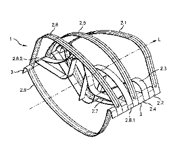
In Fig. 1, the packing element according to the invention is shown in a
perspective represen-
tation. The packing element 1 comprises a plurality of, in the represented
embodiment nine,
neighbouring strips 2,1, 2.2, 2.3, 2.4, 2.5, 2.6, 2.7, 2.8, 2.9. The strips
2.1, 2.2, 2.3, 2.4, 2.5,
2.6, 2.7, 2.8, 2.9 are, starting from a first mid-plane M1 (see Fig. 2) of the
packing element 1,
bent open outwards and thus determine the volume of the packing element 1. The
strips are
band-like (lamellar) having a width band a length I. The exact shape of the
strips 2.1, 2.2, 2.3,
2.4, 2.5, 2.6, 21, 2.8, 2.9 will be illustrated more in detail with reference
to the following figures.
Preferably, all strips have the same width b, in the represented embodiment it
is 5 mm. How-
ever, it would also be possible that at least some strips have different
widths. The length I of
all strips is equal. At both edges of the packing element 1, transverse webs
3, 4 are formed in
parallel to a longitudinal axis L of the packing element 1. The strips 2.1,
2.2, 2.3, 2.4, 2.5, 2.6,
2.7, 2.8, 2.9 end in the transverse webs 3, 4 and are firmly connected
thereto. Thereby, each
one of the strips 2.1, 2.2, 2.3, 2.4, 2.5, 2,6, 2.7, 2.8, 2,9 is connected to
the respective neigh-
bouring strip(s) 2.1, 2.2, 2.3, 2.4, 2.5, 2.6, 2.7, 2.8, 2.9. As can be
clearly seen in Fig. 1, the
transverse webs 3, 4 extend in parallel to the longitudinal axis L of the
packing element 1. The
strips 2.1, 2.2, 2.3, 2.4, 2.5, 2.6, 2.7, 2.8, 2.9 extend transverse to the
transverse webs 3, 4, I.
e. perpendicular to the longitudinal axis L of the packing element 1. The
packing element 1
may be made, for example, of metal. In this case, the packing element 1 is
made of a metal
CA 03108844 2021-02-05
7
band. Here, cuts extending in parallel to the longitudinal direction of the
metal band are incor-
porated into the metal band. The cuts do not extend across the complete width
of the metal
band, such that the transverse webs 3, 4 remain at both edges of the metal
band perpendicular
to the cuts. The strips formed by the cuts extending through the metal band in
parallel to the
longitudinal direction, that means the strips 2.1, 2.2, 2.3, 2.4, 2.5, 2.6,
2.7, 2.8, 2.9, are pressed
out of the plane of the metal band so that a three-dimensional body, the
packing element 1, is
formed. By cuts extending transverse to the longitudinal direction of the
metal band, the indi-
vidual packing elements are separated from the metal band. Individual strips
may be split into
two segments with short cuts extending transverse to the longitudinal
direction of the metal
band.
As can be seen in Fig. 1, the strips 2.1, 2.2, 2.3, 2.4, 2.5, 2.6, 2.7, 2.8,
2.9 extend on both sides
of the plane of the originally flat metal band and enclose a volume V. All
strips 2.1, 2.2, 2.3,
2.4, 2.5, 2.6, 2.7, 2.8, 2.9 are provided in the process with an arch shape
having at least one
vertex. A vertex is here the highest or lowest point of an arc or a sector. At
least one of the
strips 2.1, 2.2, 2.3, 2.4, 2.5, 2.6, 2.7, 2.8, 2.9 has an irregular shape. The
term õirregular shape"
means that at least one of the strips highly differs from a sine wave shape
and does not have
any periodically recurring elements. This means in particular that at least
one of the strips is
curved in an arch or wave shape, has at least two changes of direction in its
slope and does
not have any symmetry in itself. The exact shape of the strips 2.1, 2.2, 2.3,
2.4, 2.5, 2.6, 2.7,
2.8, 2.9 will be discussed more in detail below, in particular with reference
to Figs. 7a-i.
Fig. 2 shows a plan view onto the packing element 1 along its longitudinal
axis L. The arch
shape of the strips 2.1, 2.2, 2.3, 2.4, 2.5, 2.6, 2.7, 2.8, 2.9 can be clearly
seen. All strips 2.1,
2.2, 2.3, 2.4, 2.5, 2.6, 2.7, 2.8, 2.9 have different shapes. As can be
clearly seen, the cross-
section of the packing element 1 is approximately rectangular, therefore, the
volume V en-
closed by the strips 2.1, 2.2, 2.3, 2,4, 2.5, 2.6, 2.7, 2.8, 2.9 is
approximately cuboid. The volume
V is split by a first mid-plane M1 and a second mid-plane M2 that are
perpendicular with respect
to each other and intersect in the longitudinal axis L of the packing element
1. The first mid-
plane M1 centrically extends between a front side 6 and a back side 7 of the
packing element
1, the second mid-plane M2 extends centrically between a left side 8 and a
right side 9 of the
packing element 1.
In order to describe the shape of the strips 2.1, 2.2, 23, 2.4, 2.5, 2.6, 2.7,
2.8, 2.9 more in
detail, a coordinate system may be placed into the packing element 1. The z-
axis of the coor-
dinate system extends along the longitudinal axis L of the packing element,
the x-axis and the
CA 03108844 2021-02-05
8
y-axis are perpendicular with respect to each other and with respect to the z-
axis. That means,
in Fig. 2, the x-axis extends along the two-dimensional representation of the
first mid-plane
Ml, the y-axis extends along the two-dimensional representation of the second
mid-plane M2,
the z-axis extends in the intersection of the two mid-planes Ml, M2, that
means, as already
described, along the longitudinal axis L of the packing element 1. The shape
of the strips 2.1,
2.2, 2.3, 2.4, 2.5, 2.6, 2.7, 2.8, 2.9 may thus be described in the x-y-plane,
that means in the
plane perpendicular to the z-axis and thus to the longitudinal axis L of the
packing element 1,
with a shape of a curve, in the present case referred to as arch shape, and
will be illustrated
more in detail below.
In WO 2008/067031 A2, too, the individual strips can be described with
reference to such a
coordinate system. Here, too, the z-axis extends along the longitudinal axis
of the packing
element, which, however, is curved. Therefore, the z-axis is also curved. The
shape of the
individual strips may again also be described by a curve in the x-y-plane of
the coordinate
system, that means a plane perpendicular to the z-axis. Both in the embodiment
shown in Figs.
Ito 13 and in the embodiment shown in Figs. 14 to 26, the curve shape of the
strip is partially
identical. The strips with identical strip shapes only differ in that they are
arranged at different
positions of the z-axis. Moreover, the strips are at least partially point-
symmetrical to the origin
of the coordinate system.
The cuboid shape of the packing element 1 is achieved in that four of the
strips, i. e. the first
strip 2.1, the second strip 2.2, the eighth strip 2.8 and the ninth strip 2.9,
have an asymmetrical
arch shape having one vertex Si, S2, S8, 89 each, wherein two of these four
strips, I. e. the
first strip 2.1 and the eighth strip 2.8, extend on the one side of the first
mid-plane Ml, and the
other two of these four strips, I. e. the second strip 2.2 and the ninth strip
2.9, extend on the
other side of the first mid-plane Ml. The vertices S1, S2, S8, S9 of these
four strips 2.1, 2.2,
2.8, 2.9 are each located next to the second mid-plane M2. Here, the vertices
Si, 88; S2, 59
of the strips 2.1, 2.8; 2.2, 2.9, which are each located on the same side of
the first mid-plane
Ml, are arranged on different sides of the second mid-plane M2. These four
strips 2.1, 2.2,
2.8, 2 9 are formed at the upper and lower ends of the packing element 1,
where two strips
2.1, 2.2; 2.8, 2.9 each are arranged at each end which each extend on
different sides of the
first mid-plane Ml, and whose vertices S1, S2; S8, S9 are arranged on
different sides of the
second mid-plane M2.
CA 03108844 2021-02-05 ,
9
Moreover, the packing element comprises a central strip 2.5 which has a
symmetrical arch
shape with a vertex 55. The vertex S5 of this strip 2.5 is therefore located
in the second mid-
plane M2. The central strip 2,5 extends towards the back side 7 of the packing
element 1.
Since the strips 2.1, 2.2,2.5, 2.8, 2.9 only have one vertex S1, S2, S5, S8,
S9 each, they have
a relatively high height and thus form an outer wall or outer hull of the
packing element 1. Two
multiply curved strips, the third strip 2.3 and the fourth strip 2.4, are
arranged between the two
strips 21, 2.2 formed at the first edge of the packing element, and the
central strip 2.5.
The third strip 2.3 has an asymmetrical arch shape having three vertices 83.1,
83.2, 83.3,
wherein the central vertex S3.2 extends to a side of the first mid-plane M1
other than the two
other vertices S3.1, S3.3. Moreover, the central vertex S3.2 has a greater
distance from the
first mid-plane M1 than the other two vertices S3.1, S3.3. The two outer
vertices S3.1, 83.3
both have the same distance to the first mid-plane 1. The central vertex S3.2
therefore has a
higher height or a higher amplitude, respectively, than the two outer vertices
83.1, 83.3. In the
shown plan view, the central vertex S3.2 is located right of the second mid-
plane M2. The
distance from the left transverse web 3 of the packing element 1 to the
central vertex S3.2 of
the strip 2.3 is therefore greater than the distance from the right transverse
web 4 of the pack-
ing element 1 to the central vertex S3.2. Thus, the wavelength of the left
region of the strip 2.3,
i. e. starting from the left transverse web 3, to the central vertex S3.2 is
greater than the wave-
length of the right region of the strip 2.3, i. e. starting from the central
vertex S3,2 to the right
transverse web 4.
The fourth strip 2.4 is split into two segments 2.4.1 and 2.4.2. The first
segment 2.4.1 extends,
starting from the left transverse web 3 of the packing element 1, into the
interior of the volume
V of the packing element 1. The second segment 2.4.2 extends, starting from
the right trans-
verse web 4 of the packing element 1, into the interior of the volume V of the
packing element.
The two segments 2.4.1, 2.4.2 have different lengths, wherein the first, the
left segment 2.4.1
is shorter than the second, the right segment 2.4.2. The first segment 2.4.1
extends, starting
from the left transverse web 3, with a concave curvature, i. e. curved to the
top in Fig. 2, in the
direction of the front side 6 of the packing element 1. This means, the first
segment 2.4,1 has
no vertex. The second segment 2.4.2 points, starting from the right transverse
web 4, also in
the direction of the front side 6 of the packing element 1, however, in a
straight line, has a
vertex S4 and extends, behind the vertex S4, again in a relatively straight
line to the top in the
direction of the back side 7 of the packing element 1. The ends of the two
segments 2.4.1 and
2,4.2 therefore face in different directions and are spaced apart with respect
to each other.
CA 03106844 2021-02-05
By the multiple bending of the strips 2.3, 2.4, these strips 2.3, 2.4 have a
lower height than the
edge strips 2.1, 2.2, 2.8, 2.9, and the central strip 2.5.
Between the other two edge strips 2.8, 2.9 and the central strip 2.5, two
multiply curved strips,
the sixth strip 2.6 and the seventh strip 2.7, are arranged. The sixth strip
2.6 is arranged next
to the central strip 2.5. The sixth strip 2.6 is also split into two segments
2.6.1, 2.6.2. The two
segments 2.6.1, 2.6.2 have different lengths, wherein the first segment 2.6.1
starting from the
left transverse web 3 is longer than the second segment 2.6.2 starting from
the right transverse
web 4. The first segment 2.6.1 extends, starting from the left transverse web
3, curved to the
top, that means concavely, in the direction of the back side 7 of the packing
element 1 to a
vertex S6. There, the slope of the segment 2.6.1 changes direction, that means
changes the
digit sign, and the segment 2.6.1 extends from there in a straight line in the
direction towards
the front side 6 of the packing element 1 and intersects the second mid-plane
M2 in the pro-
cess. The second segment 2.6.2 extends, starting from the right transverse web
4, curved to
the bottom, that means convexly, in the direction towards the back side 7 of
the packing ele-
ment 1. The ends of the two segments 2.6.1 and 2.6.2 are spaced apart and are
located on
different sides of the first mid-plane Ml.
The seventh strip 2.7 is again a continuous strip having an asymmetrical arch
shape and has
three vertices S7.1, 57.2, S7.3. The central vertex S7.2 is located on a first
side of the first
mid-plane M1 facing the back side 7 of the packing element 1, the two other
ones, the outer
vertices S7.1, S7.3, are located on the other side of the first mid-plane M1
facing the front side
6 of the packing element 1. The central vertex S7.2 has a greater distance to
the first mid-
plane M1 than the other two vertices S7.1, S7.3. The two outer vertices S7.1,
S7.3 have the
same distance to the first mid-plane Ml. The central vertex S7.2 therefore has
a higher ampli-
tude than the two outer vertices S7.1, S7.3. The central vertex S7.2 is
located in the left next
to the second mid-plane M2, such that the distance from the first, the left
transverse web 3 to
the central vertex S7.2 is smaller than the distance from the central vertex
S7.2 to the second,
the right transverse web 4 of the packing element 1. The left region of the
strip 2.7, I. e. starting
from the left transverse web 3 to the central vertex S7.2, therefore has a
smaller wavelength
than the right region of the strip 2.7, that means starting from the central
vertex S7.2 to the
right transverse web 4 of the packing element 1. The sixth strip 2.6 and the
seventh strip 2.7
are again lower than the edge strips 2.1, 2 2, 2.8, 2.9 and the central strip
2.5.
The third, fourth, sixth and seventh strips 2.3, 2.4, 2.6, and 2.7 therefore
split the packing
element 1 transverse to the longitudinal axis L (see Fig. 2). Fluids flowing
through the packing
CA 031.08844 2021-02-05
11
element 1 in the longitudinal direction are therefore split or interrupted,
such that the formation
of fluid conduits is avoided and the separation performance improved.
Fig. 3 shows the right side view of the packing element 1. The different
heights of the nine
strips 2.1, 2.2, 2.3, 2.4, 2.5, 2.6, 2.7, 2.8, 2.9 can be easily seen. The
first strip 2.1, the second
strip 2.2, the fifth strip 2.5, the eighth strip 2.8, and the ninth strip 2.9
have approximately the
same height, wherein the second strip 2.2 and the ninth strip 2.9 extend to
the other side of
the first mid-plane M1 of the packing element 1 than the first strip 2.1, the
fifth strip 2,5, and
the eighth strip 2.8. The third strip 2.3, the fourth strip 2.4, the sixth
strip 2.6 and the seventh
strip 2.7 extend, starting from the first mid-plane Ml, each in both
directions of the packing
element 1 and therefore have a clearly lower height than the other strips.
Therefore, the pack-
ing element has a large open projected cross-sectional area in this axis. This
can also be seen
in Fig. 4 where the left side view of the packing element is shown. All strips
2.1, 2.2, 2.3, 2.4,
2,5, 2.6, 2.7, 2.8, 2.9 have the same width b. The edge strips 2.1, 2.2, 2.8,
2.9 and the central
strip 2.5 are provided with a bead 5. This increases the strength of the
packing element 1. The
lower strips 2.3, 2.4, 2.6, 2.7 do not have a bead. This results in a function
separation of the
strips into the strips 2.1, 2.2, 2.8, 2.9, 2.5 which provide strength, and the
strips 2.3, 2.4, 2.6,
2.7 which provide phase distribution.
Fig. 5 shows the front side 6 of the packing element 1, Fig. 6 shows the back
side 7 of the
packing element 1. All strips 2.1, 2,2, 2.3, 2.4, 2.5, 2.6, 2.7, 2.8, 2,9
extend in parallel with
respect to each other and have the same widths b. The open projected cross-
sectional area in
this axis is rather small. Only the split strips 2.4 and 2.6 provide open
areas.
In Figs. 7a to 7i, the individual strips are each shown in a view
perpendicular to the longitudinal
axis L of the packing element.
Fig. 7a shows the first strip 2.1. This strip 2,1 is an edge strip. The first
strip 2.1 has an asym-
metrical arch shape having one vertex Si. The vertex Si is arranged
eccentrically, i. e. the
distance from the first, I. e. the left transverse web 3 to the vertex Si is
smaller than the dis-
tance from the second, I. e. the right transverse web 4 to the vertex Si. The
strip 2.1 is curved
to the top, i. e. it has a concave curvature. At the transition to the right
transverse web 4, the
strip 2.1 has a sharp bend. For the complete description of Fig. 7, i. e. for
Figs. 7a to 7i, the
term ,,to the top" means facing to the back side 7 of the packing element 1.
Correspondingly,
the term to the bottom" means facing to the front side 6 of the packing
element 1.
CA 03108844 2021-02-05
12
Fig, 7b shows the second strip 2.2. This strip 2,2 is also an edge strip. The
second strip 2.2
also has an asymmetrical arch shape having one vertex S2, wherein the distance
from the
first, i. e. the left transverse web 3 to the vertex S2 is greater than the
distance from the second,
I. e, the right transverse web 4 to the vertex S2, The strip 2.2 is curved
downwards, that is it
has a convex curvature, wherein the two lateral transverse webs 3, 4 extend to
the top and the
second strip 2.2 only bends sharply after that.
In Fig. 7c, the third strip 2,3 is shown. The third strip 2.3 has an
asymmetrical arch shape
having three vertices S3.1, S3.2, S3.3. Starting from the first, i. e. the
left transverse web 3,
the third strip 2.3 extends to the top up to the first outer vertex S3.1. From
the first outer vertex
S3.1, the third strip 2,3 extends relatively straightly to the bottom, and
includes an angle of
about 400 with the first mid-plane Ml, to the second, the central vertex S3.2,
and from there
extends again relatively straightly, including an angle of about 550 with the
first mid-plane Ml,
to the top to the third, also an outer, vertex S3.3. The central vertex S3.2
has a greater distance
from the first mid-plane M1 (see Fig. 2) than the first vertex S3.1 and the
third vertex S3.3. The
first vertex S3.1 and the third vertex S3.3 have approximately the same
distance from the first
mid-plane Ml. The distance from the first, I. e. the left transverse web 3 to
the central vertex
S3.2 is greater than the distance from the second, i. e. the right transverse
web 4 to the central
vertex S3.2. The two outer vertices S3.1, 53.3 approximately have the same
lateral distance
to the respective neighbouring transverse web 3, 4. Therefore, the distance
from the first outer
vertex S3.1 to the central vertex S3.2 is greater than the distance from the
second outer vertex
S3.3 to the central vertex S3.2.
Fig, 7d shows the fourth strip 2.4, The fourth strip 2.4 is a split strip and
comprises the two
segments 2.4.1 and 2.4.2. The first segment 2.4.1 is shorter than the second
segment 2.4.2.
The first segment 2.4.1 shortly extends to the top, this length approximately
corresponds to
the left transverse web 3, and then sharply bends in the direction of the
front side 6 of the
packing element 1 and extends to the top in a curved manner, i. e. concavely.
The second
segment 2.4.2 of the strip 2.4 shortly extends to the top, this corresponds to
the right transverse
web 4, then sharply bends to the bottom and extends relatively straightly,
including an angle
of approximately 45 with the first mid-plane Ml, to a vertex S4. There, the
direction of the
slope of the segment 2.4.2 changes, and the segment 2.4.2 extends straightly,
including an
angle of about 70 with the first mid-plane Ml, to the top up to the end of
the segment 2.4.2.
The ends of the two segments 2.4.1 and 2.4.2 are spaced apart and face into
different direc-
tions
CA 03108844 2021-02-05
13
Fig. 7e shows the fifth strip 2.5. The fifth strip 2.5 has a symmetrical arch
shape having a vertex
S5. The vertex S5 also has the same distance from both transverse webs 3, 4.
The central
strip 2.5 is curved to the top, i. e. it has a concave curvature and is only
formed on one side of
the first mid-plane Ml.
Fig. 7f shows the sixth strip 2.6. This is again a split strip, i. e. the
strip 2.6 comprises two
segments 2.6.1 and 2.6.2. The ends of the two segments 2.6.1 and 2.6.2 are
spaced apart.
The segment 2,6,1 in the left in Fig, 7f extends, starting from the left
transverse web 3, with a
concave curvature to the top up to a vertex S6 and leads from there to the
bottom, essentially
along a straight line that includes an angle of approximately 800 with the
first mid-plane Ml.
The second, right segment 2.6.2 follows the right transverse web 4 at an angle
of approxi-
mately 900 and leads from there in a convex curvature inwards and to the top.
The ends of the
two segments 2.6.1 and 2.6.2 are located on different sides of the first mid-
plane Ml. The first
segment 2.6.1 is longer than the second segment 2.6.2.
Fig. 7g shows the seventh strip 2.7. This is a low strip with an asymmetrical
arch shape having
three vertices S7.1, S7.2, S7.3. The strip 7.2 follows the left transverse web
3 at an angle of
about 90 , extends straightly to the bottom and includes an angle of about 25
with the first
mid-plane M1 and passes over into a first lower vertex 37.1 with a curvature.
Starting from this
first lower vertex 37.1, the strip 7.2 extends to the top with a curvature and
passes over into a
straight line including an angle of about 750 with the first mid-plane Ml. The
straight line in turn
passes over into a central upper vertex S7.2 with a curvature. Starting from
this central vertex
37.2, the strip 7.2 turns again to the bottom with a slight curvature and
passes over into a
straight line including an angle of about 750 with the first mid-plane M1 and
passing over into
a second lower vertex S7.3 with a curvature. Starting from the second lower
vertex S7.3, the
seventh strip 2.7 passes over into a straight section with a curvature
including an angle of
about 15 with the first mid-plane M1 and ending in the right transverse web 4
at an angle of
about 90 . The first lower vertex S7,1 and the second lower vertex S7.3
approximately have
the same distance to the first mid-plane Ml. This distance is smaller than the
distance of the
central upper vertex S7.2 to the first mid-plane Ml. The central vertex 37.2
also has a higher
height or higher amplitude, respectively, than the lower vertices S71 and
S7.3. The first lower
vertex S7.1 and the second lower vertex S7.3 have the same lateral distance to
the central
vertex 57.2. However, the two lower vertices S7.1 and 37.3 have different
distances to the
respective neighbouring transverse web 3, 4. The distance of the first lower
vertex S7.1 to the
left transverse web 3 is smaller than the distance of the second lower vertex
S7.3 to the right
CA 03100544 2021-02-05
14
transverse web 4. Thus, the central vertex S7.2, too, has different distances
to the transverse
webs 3, 4.
Fig. 7h shows the eighth strip 2.8. The eighth strip 2.8 has an asymmetrical
arch shape having
one vertex 58. Starting from the left transverse web 3 which is followed by
the eighth strip 2.8
at an angle of about 135', the eighth strip 2.8 curves to the top (concave
curvature) up to the
vertex 58. At the vertex S8, the direction of the slope of the eighth strip
2.8 changes, and the
eighth strip 2.8 extends again to the bottom, passes over into a straight
region which straightly
passes over into the right transverse web 4. The distance from the left
transverse web 3 to the
vertex S8 is greater than the distance from the vertex S8 to the right
transverse web 4.
Fig. 7i shows the ninth strip 2.9. The ninth strip 2.9 follows the left
transverse web 3 and ex-
tends from there with a convex curvature to the bottom down to a vertex S9.
Starting from the
vertex S9, the ninth strip 2.9 extends again to the top and passes over into
the right transverse
web 4. The strip 2.9 has again an asymmetrical arch shape having one vertex
S9, that means
the distance from the left transverse web 3 to the vertex S9 is smaller than
the distance from
the vertex S9 to the right transverse web 4.
The two transverse webs 3, 4 always extend slightly obliquely to the top. The
nine strips 2.1,
2.2, 2.3, 2.4, 2.5, 2.6, 2.7, 2.8, 2.9 smoothly pass over into the transverse
webs 3, 4.
The strips 2.3, 2.4, 2.6, 2.7, the low strips, have a lower height than the
strips 2.1, 2.2, 2.5, 2.8,
2.9, the high strips.
The transverse webs are not part of the strips.
As materials for the packing element, preferably metals, for example high-
quality steel, are
employed. However, it would also be conceivable to produce such packing
elements from
plastic. The above-described manufacturing process is, of course, not
applicable to packing
element of plastic.
CA 03108844 2021-02-05
List of reference numerals
1 packing element
2.1 first strip
2.2 second strip
2.3 third strip
2,4 fourth strip
2.4.1 first segment of fourth strip
2.4.2 second segment of fourth strip
2,5 fifth or central strip
2,6 sixth strip
2,6.1 first segment of sixth strip
2.6.2 second segment of sixth strip
2.7 seventh strip
2.8 eighth strip
2.9 ninth strip
3 left transverse web
4 right transverse web
5 bead
6 front side of packing element
7 back side of packing element
8 left side of packing element
9 right side of packing element
M1 first mid-plane
M2 second mid-plane
I. longitudinal axis of packing element
V volume of packing element
CA 03108844 2021-02-05
, .
16
b width of strips
I length of strips
Si vertex of first strip
S2 vertex of second strip
S3.1 first vertex of third strip
63.2 second vertex of third strip
S3.3 third vertex of third strip
S4 vertex of fourth strip
S5 vertex of fifth strip
S6 vertex of sixth strip
S7.1 first vertex of seventh strip
S7.2 second vertex of seventh strip
S7.3 third vertex of seventh strip
S8 vertex of eighth strip
S9 vertex of ninth strip