Note: Descriptions are shown in the official language in which they were submitted.
1
A SEPARATION APPARATUS AND METHOD
CROSS-REFERENCE(S) TO RELATED APPLICATIONS
This application claims priority from South African provisional patent
application number
2018/05502 filed on 17 August 2018.
FIELD OF THE INVENTION
This invention relates to the field of mineral processing and, in particular,
it relates to the
separation of minerals found in ores.
In this specification "ore" has its widest meaning and includes any naturally
occurring solid
material from which minerals of economic interest may be extracted.
BACKGROUND TO THE INVENTION
Excavated mineral ores from rock require mineral processing, also known as ore
dressing, the
main objective of which involves separation of valuable minerals from the
waste material. This
may typically involve particle size reduction; separation of particle size by
screening or
classification or concentration, which employs physical and surface chemical
properties and
solid/liquid separation.
Examples of commonly known valuable minerals include: gold, gemstones,
diamonds, placer tin,
copper, coal and the like. Most of the latter examples are extracted from
mineral ores by the use
of devices that are referred to in the art as jig concentrators. Jig
concentrators are devices utilized
in mineral processing to separate particles within the ore body based on their
specific gravity,
size, shape and density.
Particles of ore are introduced to a so-called jig bed where they are thrust
upward by a pulsing
fluid body. Water is the most common fluid that is used, however, additives
that aid separation
may be added. The pulsing water thrusts the particles upward resulting in some
of the particles
being suspended within the water. As the pulse dissipates, the water level
returns to its lower
starting position, whereafter the particles once again settle on the jig bed.
As the particles are
exposed to gravitational force whilst suspended within the water, heavier
particles (with a higher
Date Recue/Date Received 2023-06-22
CA 03109906 2021-02-17
WO 2020/035746
PCT3B2019/052598
2
specific gravity) settle faster than lighter particles resulting in a
concentration of heavier particles
at the bottom on the jig bed. The heavier particles may then be extracted from
the jig bed, whereas
lighter particles may be extracted from an upper region of the jig.
Commonly available concentrator jigs typically have large tanks or receptacles
housing a bed on
which anything from 3 tonnes of solid material to as much as 100 tonnes per
hour, may be
processed, depending on size. Moreover, these large tanks are coupled to
loading and collection
mechanisms which may include conveyor belts and support beams. The tanks also
require a
correspondingly effective fluid pulsing mechanism capable of providing a pulse
sufficient to lift the
.. ore particles in the tank. In known jig concentrators the ore is introduced
at a top opening of the
device requiring the tank of the device to be very large to enable the
particles to settle properly.
Accordingly, the commonly available concentrator jigs are quite large overall,
typically having one
or more tanks large enough to house several cubic meters of ore and water.
Similarly, due to the
.. size of the tanks, the jigs consume large volumes of water and a large
volume of water is in the
tank at any given point in time, requiring a substantial amount of force to
pulsate the water. This,
in turn, requires a very large pump and mechanical components. Moreover, due
to the significantly
large pulsing mechanism required to pulse the water in the large tanks, the
jigs consume a lot of
electricity. Finally, due to the size of the jigs, the use thereof is
generally confined to operation on
.. land only in immobile environments.
There is accordingly a need for a separation apparatus and method which
alleviates the
abovementioned problems at least to some extent.
.. The preceding discussion of the background to the invention is intended
only to facilitate an
understanding of the present invention. It should be appreciated that the
discussion is not an
acknowledgment or admission that any of the material referred to was part of
the common general
knowledge in the art as at the priority date of the application.
SUMMARY OF THE INVENTION
In accordance with the invention there is provided a separation apparatus
comprising:
a separation chamber having a permeable separator member located near a bottom
region thereof, a first chamber outlet located near an upper region of the
chamber and a second
chamber outlet located near the bottom region of the chamber, the chamber
being configured to
be utilised with a fluid pulsing mechanism for operatively pulsating a fluid
through ore deposited
in the chamber resulting in the migration of generally lighter ore particles
toward the upper region
CA 03109906 2021-02-17
WO 2020/035746
PCT/IB2019/052598
3
of the chamber and for generally heavier ore particles to migrate toward the
bottom region of the
chamber,
characterised in that an ore deposit chute is provided through which ore may
be deposited
near the bottom region of the chamber remote from the first chamber outlet,
with the chute outlet
being disposed lower in the chamber than the first chamber outlet.
Further features provide for the chute to include an inlet and an outlet; for
the chute to taper
outwardly from the inlet toward the outlet thereof; for the inlet of the chute
to be configured to
receive a trough, conveyor mechanism or the like for feeding ore into the
chute; for at least part
.. of a lower part of the chute to be operatively submerged in the pulsating
fluid, preferably for the
chute outlet to be operatively submerged in the pulsating fluid; for the chute
to extend through the
chamber from the upper region thereof to the bottom region thereof,
alternatively for the chute to
be provided externally of the chamber and for the chamber to include an inlet
in communication
with the outlet of the chute so as to enable depositing of ore near the bottom
region of the chamber
through the outlet of the chute.
Even further features provide for the separator member to define a bottom of
the chamber; for the
separator member to be secured within the chamber at an angle relative to a
top of the chamber,
alternatively for the separator member to be secured within the chamber at an
angle relative to
the first outlet; for the separator member to be permanently secured within
the chamber at a
preselected angle, alternatively for the separator member to be at least
partially rotatable so as
to enable adjustment of the angle relative to the top of the chamber, relative
to the first outlet of
the chamber or relative to the outlet of the chute; and for the separator
member to be in the form
of a permeable plate through which pulsating fluid may be pulsed.
Yet further features provide for the second chamber outlet to be located on
the same side of the
chamber as the first chamber outlet; alternatively, for the second chamber
outlet to be located on
a side of the chamber opposite or remote from that of the first chamber
outlet; for a blanking off
plate to be provided within the chamber that is configured to reduce the size
of the chamber while
maintaining the pulse volume thereby increasing the pulse length; and for the
location of the
second chamber outlet to be selected depending on the angle of the separator
member relative
to the first outlet of the chamber.
Still further features provide for the fluid pulsing mechanism to pulsate
fluid mechanically,
alternatively hydraulically by means of a flexible diaphragm or air operating
on a fluid surface or
a combination thereof; for the fluid pulsing mechanism to be configurable so
as to configure the
CA 03109906 2021-02-17
WO 2020/035746
PCT/IB2019/052598
4
velocity of the pulsed fluid; and for the velocity of the pulsed fluid to be
selected depending on the
specific gravity and particle size of the material to be separated.
In accordance with this invention there is provided a method of separating ore
by means of a
separator apparatus, the method including the steps of:
introducing ore into a separation chamber of a separator apparatus, the ore
being
introduced through a chute having an outlet disposed lower in the chamber
relative to a first
chamber outlet so that the ore is introduced through the chute outlet into the
chamber near an
operatively bottom region of the chamber; and
pulsating a fluid through ore introduced into the chamber resulting in the
migration of
generally lighter ore particles toward an upper region of the chamber and the
migration of
generally heavier ore particles toward the bottom region of the chamber.
Further features provide for the first chamber outlet to be provided in the
upper region of the
chamber and for a second chamber outlet to be provided in the bottom region of
the chamber and
for the method to include the steps of extracting or discharging the generally
lighter ore particles
through the first chamber outlet and the generally heavier ore particles
through the second
chamber outlet.
An embodiment of the invention will now be described, by way of example only,
with reference to
the accompanying drawings.
BRIEF DESCRIPTION OF THE DRAWINGS
In the drawings:
Figure 1
is a three-dimensional view of a separation apparatus according to an
embodiment of the invention;
Figure 2 is a side view of the separation apparatus of Figure 1;
Figure 3
is a sectional view of the separation apparatus along line D-D in Figure
2,
illustrating a separation chamber and a chute for receiving ore;
Figure 4 is a
three-dimensional sectional view of the separation apparatus also along
line D-D in Figure 2, but viewed from an opposite side than Figure 3; and
CA 03109906 2021-02-17
WO 2020/035746
PCT/IB2019/052598
Figure 5
is a sectional view of a separation apparatus according to an embodiment
of
the invention in which a blanking off plate is provided in the chamber.
DETAILED DESCRIPTION WITH REFERENCE TO THE DRAWINGS
5
An example embodiment disclosed herein provides a separation apparatus. The
apparatus may
include a separation chamber having a permeable separator member disposed near
a bottom
region thereof. The permeable separator member may form a grid surface or
other support that
may support ore deposited into the separation chamber. The chamber may include
a first outlet
located near an upper region of the chamber and a second outlet located near
the bottom region
of the chamber. The two outlets may be disposed on the same wall of the
chamber, alternatively
the two outlets may be disposed on opposing walls of the chamber. The
separation apparatus
may include a fluid pulsing mechanism disposed near the bottom region of the
chamber, below
the separator member, for pulsating a fluid through the separator member and
any ore deposited
in the chamber. This pulsation may result in at least some of the ore becoming
suspended in the
fluid and may cause the migration of generally lighter ore particles (that may
have generally lower
specific gravity) toward the upper region of the chamber where the particles
may be extracted
from the chamber through the first outlet and generally heavier ore particles
(that may have
generally higher specific gravity) to migrate toward the bottom region of the
chamber where the
particles may be extracted from the chamber through the second outlet. The
separation apparatus
or jig concentrator may have an ore deposit chute through which, in use, ore
may be deposited
near the bottom region of the chamber, preferably directly onto the separator
member, generally
opposite the first outlet and remote from a top of the chamber. The chute's
outlet may be disposed
lower in the chamber relative to the first outlet. It will be appreciated that
since ore may be
deposited near the bottom region of the chamber and lower in the chamber
relative to the first
outlet, the heavier particles will no longer need to migrate to the bottom
region and only the
generally lighter particles will migrate through the generally heavier
particles to the upper region
of the chamber. This aspect allows for a significantly thicker layer of ore to
be supported on the
separator member than in current systems known in the art, as will be
described in more detail
further below. In addition, this aspect allows for a significantly higher ore
throughput per area of
the separation chamber as may be provided by known systems.
The chute may taper or have a funnel-like shape toward the outlet thereof to
facilitate the flow of
ore therethrough. Making use of a chute that tapers outwardly from its inlet
toward its outlet results
in ore being drawn through the chute into the chamber due to the ore being
compressed into the
tapering chute on the upward stroke of the fluid pulsing mechanism, while
being drawn
downwardly toward the outlet of the chute during the downward stroke of the
pulse.
CA 03109906 2021-02-17
WO 2020/035746
PCT/IB2019/052598
6
The inlet of the chute may be configured to receive a trough, conveyor
mechanism or the like for
feeding ore into the chamber via the chute. The chute may be in the form of a
hopper. Further,
the chute may extend internally of the chamber from the upper region thereof
to the bottom region
thereof, alternatively, the chute may be provided externally of the chamber in
which case the
chamber may include an inlet in communication with the outlet of the chute.
The separator member may be secured within the chamber at an angle relative to
the top of the
chamber or relative to the first outlet of the chamber. The separator member
may be fixed within
the chamber about its periphery at a preselected angle. Alternatively, the
separator member may
be at least partially rotatable so as to enable adjustment of the angle
relative to the top of the
chamber or the first outlet of the chamber or even the chute outlet. The angle
of the separator
member may be selected depending on the specific gravity of the ore to be
separated. It will be
appreciated that the angle of the separator member may assist in conveying the
generally heavier
ore particles, which migrate to or locate near the separator member, toward
the second outlet for
extraction thereof from the chamber. Accordingly, the location of the second
outlet may be
selected depending on the angle of the separator member relative to the first
outlet. As such, the
second outlet may be disposed in the same side wall of the chamber as the
first outlet,
alternatively the second outlet may be disposed in a side wall of the chamber
that is opposite to
or remote from the side wall in which the first outlet is disposed.
There is also provided a method of separating ore by means of a separator
apparatus. The
method may include the steps of: introducing ore into a separation chamber of
the separator
apparatus via a chute, the chute including an outlet for depositing ore within
the chamber, the
outlet of the chute being disposed lower in the chamber relative to a first
chamber outlet so that
the ore is introduced though the chute outlet into the chamber near an
operatively bottom region
of the chamber, and pulsating a fluid through ore deposited in the chamber
resulting in the
migration of generally lighter ore particles toward an upper region of the
chamber and the
migration of generally heavier ore particles toward the bottom region of the
chamber.
A float (sometimes referred to as tailings) may be discharged from the first
outlet, while a
concentrate may be discharged from the second outlet. The desired mineral to
be separated may
be discharged via either one of the outlets depending on the density, size and
chemical properties
of the mineral. The float may comprise the lighter ore particles, while the
concentrate may
comprise the heavier ore particles. Ore particles may be deposited directly
onto the separator
member by the chute outlet thereby reducing the time that would otherwise be
required for heavy
ore particles to settle or sink towards the bottom region of the chamber where
the separator
CA 03109906 2021-02-17
WO 2020/035746
PCT/IB2019/052598
7
member is disposed. As a result, the dimensions of the chamber may be
significantly reduced,
when compared to currently available systems, thus permitting the separator
apparatus to be
substantially portable.
A specific example embodiment of the separation apparatus is now described in
greater detail
with reference to the accompanying figures, wherein like reference numerals
are used to indicate
like features.
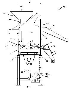
Figures 1 to 4 show various views of a separation apparatus (10) according to
an example
.. embodiment. The separation apparatus (10) includes a separation chamber
(12) which may be
box-like in shape and which includes a bottom (14), an open top (16) and four
side walls (18). A
permeable separator member (20) is mounted or otherwise attached to the side
walls (18) of the
chamber (12) within the bottom or lower region (22) thereof. The separator
member (20) is
mounted at an angle (a) relative to the bottom (14), the top (16) or to a
first outlet (24) provided
in an upper region (25) of the chamber (12). The separator member (20) may be
fixed at a
particular angle (a) or it may be mounted in a way which permits adjustment of
the angle (a), as
may be required. The angle (a) may be selected depending on the specific
gravity of the ore
particles to be separated. The separator member (20) may be in the form of a
permeable or
porous plate or grid through which a pulsating fluid, typically water, may be
pulsed, as will be
.. described in more detail further below. The first outlet (24) includes a
first spout (26) that extends
away from the separation chamber (12). A second outlet (28) is provided in the
bottom region
(22) of the chamber (12) near the bottom (14) and generally adjacent the
separator member (20)
and includes a second spout (30) which also extends away from the chamber
(12). The location
of the second outlet (28) and second spout (30) may be changed depending on
the angle (a) at
which the separator member (20) is mounted relative to the bottom (14), the
top (16) or the first
outlet (24). As such, the second outlet (28) may be provided in the same side
wall as the first
outlet (24) or it may be provided in a side wall opposite to or remote from
the side wall in which
the first outlet (24) is provided.
In addition, a fluid pulsing mechanism (32) is provided in the bottom region
(22) of the chamber
(12), disposed near the bottom (14) of the chamber (12) and below the
separator member (20).
In the embodiment shown, the fluid pulsing mechanism (32) is connected to a
shaft (34) that
extends through the bottom (14) of the chamber (12) and which in turn is
connected to a drive
mechanism (36), such as an electrical or mechanical pump. The drive mechanism
(36) is
.. configured to move the shaft (34) in a vertical direction up and down,
thereby moving the fluid
pulsing mechanism (32) vertically within the chamber (12). In use, as will be
described in more
detail below, the chamber is substantially filled with a pulsing fluid,
typically water, and the vertical
CA 03109906 2021-02-17
WO 2020/035746
PCT/IB2019/052598
8
movement of the fluid pulsing mechanism (32) causes the fluid to be pulsed
generally vertically
through the separator member (20) and any ore (not shown) that may be
deposited thereon.
Pulsation of the fluid through the ore may result in at least partial
suspension of the particles,
thereby causing the generally heavier particles to migrate to the bottom
region (22) of the chamber
(12) while the generally lighter particles migrate to the upper region (25) of
the chamber.
An ore deposit chute (38) is provided and extends through the open top (16) to
the bottom region
(22) of the separation chamber (12). The chute (38) comprises an inlet (40),
which is generally
disposed externally of the chamber (12), and an outlet (42) that is generally
disposed in the bottom
region (22) of the chamber (12) via which ore may be deposited in the bottom
region (22) of the
chamber (12), preferably directly onto the separator member (20). The outlet
(42) of the chute
(38) is disposed lower in the chamber (12) than the first outlet (24) of the
chamber (12) with the
outlet (42) of the chute (38) being generally disposed near a side wall of the
separation chamber
(12) that is remote from or opposite to the side wall in which the first
outlet (24) is provided. In a
preferred embodiment and as shown in the Figures, the chute (38) is provided
internally of the
chamber (12) and extends through the open top (16) into the chamber (12) along
a side wall
thereof. However, the chute may be provided externally of the chamber (12) in
which case an
opening or inlet in the chamber may be provided that communicates with the
outlet (42) of the
chute (38) to enable ore being deposited in the lower region (22) of the
chamber (12). In addition,
in a preferred embodiment and as shown in the Figures, the chute (38) includes
a trough (44) at
its inlet (40) to facilitate introducing ore into the chute (38). The trough
(44) may be integral with
the chute (38) or it may be separate and secured to the chute (38) prior to
use.
Furthermore, the chute's (38) position, in particular the position of the
outlet (42) of the chute (38)
within the separation chamber (12), may be adjusted by sliding the chute (38)
vertically within the
chamber (12). In order to facilitate such a position change, a number of
longitudinal slots (46)
may be provided in the side walls (18) of the chamber (12) to which the chute
(38) is secured,
with the slots (46) cooperating with suitable fastening means (48), such as
bolts or the like,
through which the position of the chute (38) within the chamber (12) may be
adjusted. It should
be appreciated that in an embodiment in which the chute is provided externally
of the chamber, a
similar adjustment mechanism may be utilised. However, in such an embodiment,
the chamber
will need to be provided with a number of openings or inlets that communicate
with the outlet of
the chute. Closures may be provided which then close the openings or inlets
not in use so as to
enable filling of the chamber with the pulsating fluid.
Finally, the chute (38) preferably tapers outwardly along its length from its
inlet (40) to its outlet
(42). Tapering the chute (38) in this way may facilitate the flow of ore
through the chute since ore
CA 03109906 2021-02-17
WO 2020/035746
PCT/IB2019/052598
9
introduced into the chute (38) may be drawn out of the chute (38) during the
downward pulse of
the fluid pulsing mechanism (32). It will be appreciated that during the
upward stroke of the fluid
pulsing mechanism, the fluid will compress the ore into the chute.
Nevertheless, during the
downward stroke, a suction is created by the fluid pulsing mechanism which
results in ore being
drawn out of the chute and thus preventing any blockage within the chute (38).
In use, the apparatus (10) is utilised in a mineral processing method or a
method of separating
ore. The ore to be separated is introduced into the trough (44), typically by
means of a conveyor
mechanism (not shown) such as a conveyor belt and is then channelled through
the chute (38)
into the chamber (12) and via the outlet (42) of the chute (38) deposited onto
the separator
member (20). In addition, the chamber (12) is substantially filled with a
pulsing fluid, such as
water, with the water level typically being just below the first outlet (24).
It will of course be
appreciated that during the separation process water will be discharged from
the chamber and a
continuous flow of water into the chamber will be required to maintain the
water level in the
.. chamber. When engaged, the pulsing mechanism (32) pulses the pulsating
fluid through the
permeable separator member (20) and the ore deposited thereon. As a result,
ore deposited on
the separator member (20) is pulsed or projected upward, away from the
separator member (20),
causing the ore particles to be at least partially suspended in the fluid for
a period of time. As a
result of the different specific gravities of the ore particles, the generally
lighter ore particles
migrate toward the upper region (25) of the chamber (12) and the generally
heavier ore particles
migrate toward the bottom region (22) of the chamber. In order to increase the
time that particles
remain suspended, so as to ensure that the lighter particles migrate upwards
and the heavier
particles downwards, a constant upward fluid current may be provided through
the chamber, as
is well known in the art.
In the embodiment shown in the Figures, the chute (38) is located adjacent the
side wall of the
chamber (12) that is opposite to the side wall in which the first and second
outlets (24, 28) are
provided. In addition, the separator member (20) is angled such that the
separator member (20)
slopes downwardly from the side at which the chute (38) is provided to the
side on which the
.. outlets (24, 28) are provided. The downward slope of the separator member
(20) causes the ore
deposited thereon to move in the direction of the arrow (A) shown in Figure 3.
During the upward
stroke of the pulsing mechanism (32), the ore particles are pulsed upward and
thus become
suspended. During the downward stroke of the pulsing mechanism (32), the
suspended ore
particles settle and as a result of the slope of the separator member (20) the
particles move in the
direction of the arrow (A) and toward the first and second outlet (24, 28).
Particles with a higher
specific gravity will settle faster than particles with a lower specific
gravity, thereby causing the
lighter particles to migrate upwardly while the heavier particles settle lower
in the chamber (12)
CA 03109906 2021-02-17
WO 2020/035746
PCT/IB2019/052598
and on top of the separator member (20). As the particles move toward the
outlets (24, 28), the
lighter particles or float, which have migrated upwardly, can be extracted
from the chamber (12)
through the first outlet (24) and the heavier particles, which have migrated
downwardly or which
have settled on the separator member (20), can be extracted from the chamber
(12) through the
5 second outlet (28). Extraction through the second outlet (28) may be by
means of a vein, paddle
or screw type extractor (50), as is well known in the art, which is capable of
extracting the ore
particles and moving them in a desired direction.
Since the ore particles are deposited lower in the chamber relative to the
first outlet (24) the
10 majority of the heavier particles or a substantial portion thereof, are
already in the bottom region
(22), i.e. on the separator member (20), and thus do not first have to migrate
downward.
Accordingly, only the lighter particles need to migrate upwards, which
significantly reduces the
time required to separate the particles.
It will be appreciated that the time required to separate the particles is
directly linked to the size
of the chamber (12). The necessary maximum dimension (w) or size of the
chamber (12)
accordingly needs to be selected such that the dimension is sufficient for the
heavier particles to
migrate downwardly through the layer of ore in the chamber until they can be
extracted from the
chamber. Since, in the present case, the particles are deposited directly onto
the separator
member (20), i.e. not simply introduced from the top of the chamber, only the
lighter particles
need to migrate upwardly and hence the dimension (w) of the chamber may be
significantly
reduced when compared to current systems. It will be appreciated that the time
required to
separate the particles is dependent on the pulse frequency, the pulse length
as well as the size
and specific gravity of the particles. Furthermore, particles having a lower
specific gravity react
better or travel more when exposed to a pulse as opposed to particles having a
higher specific
gravity. Accordingly, by depositing the heavier particles at the bottom of the
chamber and only
requiring the lighter particles, which react better to a pulse, to move
upwardly, the time required
for separation can be significantly reduced and thus the overall dimensions of
the chamber can
be reduced.
Because the required time for concentrating the ore may be less, there may
correspondingly not
be a need for a large chamber size to meet a similar ore processing rate.
Thus, a more effective
and/or efficient separation and/or concentration may be achieved with the
invention described
herein.
It will be appreciated that the angle (a) of the separator member (20) may be
selected depending
on the specific gravity of the particles to be separated. For example, as
shown in the Figures, the
CA 03109906 2021-02-17
WO 2020/035746
PCT/IB2019/052598
11
separator member (20) is angled downwardly relative to the bottom (14) from
the chute outlet (42)
to the chamber outlets (24, 28), so as to cause the particles to move toward
the second outlet
(28). However, in another embodiment, the separator member (20) may be angled
differently such
that it is directed upwardly relative to the bottom (14), in which case the
second outlet (28) would
be provided on the opposite side of the chamber (12), i.e. opposite the first
outlet (24) and in close
proximity to the chute (38), so as to enable the heavier particles to be
discharged from that side
of the chamber (12).
Furthermore, due to the tapering of the chute (38) towards its outlet (42),
the ore within the chute
will be drawn out of the chute during the downward pulse of the fluid pulsing
mechanism (32),
resulting in the chute emptying and thus providing a further increase in ore
processing capability
of the apparatus (10).
In addition, it will be appreciated that the apparatus (10) may require
significantly less electricity
to power the pulsing mechanism (32) than currently available systems since the
chamber size
may be smaller and may hence require less water or fluid to be pulsated or
pumped. The overall
weight and cost of the apparatus may also be reduced and mechanical fatigue of
the motor and
the pulsing mechanism may be alleviated at least to some extent. As a result
of the reduction in
size of the separation apparatus, it may be portable or used in mobile
applications such as on a
mobile vehicle, vessel or craft. The significant benefit herein will be
apparent. For example, in the
case of diamond mining conducted offshore, the boats tend to collect the ore
out at sea and then
need to return to the harbour in order to offload the ore for separation
purposes. The apparatus
of the present invention will be small enough to be installed on a boat or
vessel and hence
separation of the ore can take place while the boat is out at sea.
Accordingly, the boat will only
have to return to the harbour with the mineral that is actually sought. This
provides a significant
time and energy saving. As described above, current systems are generally big,
heavy systems
that are substantially immobile. The combination of lesser fluid volume
consumption, lesser
energy requirement and reduced size thus provides for a cost effective
solution that is able to
operate in mobile environments such as aboard water-borne crafts or vessels or
other mobile
rigs, which may be impossible with prior art devices.
It will be appreciated that many other embodiments of a separation apparatus
may be provided
without departing from the spirit and scope of this disclosure. For example,
many variations
regarding the configuration and the materials used in the manufacture of, and
the shape and
configuration of the separation apparatus are possible. For example, the shape
of the chute and
method of position adjustment within the separation chamber may vary depending
on the overall
shape of the separation chamber and/or that of the chute. The chamber is
depicted as being
CA 03109906 2021-02-17
WO 2020/035746
PCT/IB2019/052598
12
generally box-shaped, however rounded chambers are also possible. Also, as
mentioned above,
although the chute has been illustrated in the Figures to be internally of the
chamber, it may of
course also be provided externally, in which case the chamber would be
provided with an inlet
opening that would communicate with the outlet of the chute so as to enable
depositing of ore
into or near the bottom region of the chamber.
Similarly, and as shown in Figure 5, a blanking off plate (60) may be included
in the chamber (12)
which may reduce the size of the chamber (12). This may be particularly useful
when particles
having a very high specific gravity are being separated since even though the
size of the chamber
(12) may be reduced, the pulse volume will stay the same thus increasing the
pulse length. Thus,
the volume of fluid and ore within the chamber may be reduced, but the pulsing
action is
maintained, thereby exerting a substantially larger force onto the content of
the chamber.
Nevertheless, and as shown in Figure 5, use of a blanking off plate (60) will
generally be limited
to embodiments where the second outlet (28) and corresponding second spout
(30) locate in a
sidewall (18) opposite to that of the first outlet (24) and corresponding
spout (26), i.e. on the same
side as the chute (38), with the separator member (20) being angled to extend
upwardly from the
second outlet (28) toward the first outlet (24). This will ensure that the
high specific gravity
particles that settle at the bottom of the deposit on top of the separator
member (20) can be
conveniently extracted through the second outlet (28).
Finally, the language used in the specification has been principally selected
for readability and
instructional purposes, and it may not have been selected to delineate or
circumscribe the
inventive subject matter. It is therefore intended that the scope of the
invention be limited not by
this detailed description, but rather by any claims that issue on an
application based hereon.
Accordingly, the disclosure of the embodiments of the invention is intended to
be illustrative, but
not limiting, of the scope of the invention.
Throughout the specification and claims unless the contents requires otherwise
the word
'comprise' or variations such as 'comprises' or 'comprising' will be
understood to imply the
inclusion of a stated integer or group of integers but not the exclusion of
any other integer or group
of integers.