Note: Descriptions are shown in the official language in which they were submitted.
CA 03109996 2021-02-18
TPMS TRANSMITTER FIXING STRUCTURE AND ASSEMBLING
STRUCTURE
Technical Field
The invention mainly relates to a tire pressure monitor system (TPMS), in
particular to a fixing structure and an assembling structure of a transmitter
in a TPMS
system.
Background Art
TPMS system is a real-time monitoring system for tire pressure through tire
pressure sensing unit and tire pressure monitoring unit using radio frequency
communication.
In order to realize real-time monitoring, the system is equipped with a TPMS
transmitter on each tire, which can monitor the pressure and temperature in
the tire
and send it to the TPMS receiver in the automobile. In order to realize a
fixed
mounting of the TPMS transmitter and not to fall off under various harsh
vehicle
conditions, one mounting method is to mount the TPMS transmitter on the wheel
rim
of the tire and fix it together with the valve stem. In this case, although
the TPMS
transmitter will still be loose while the automobile is driving, it will not
significantly
affect its performance.
However, with the continuous improvement of TPMS transmitter, the
requirements of its position or attitude also increase. For example, when the
TPMS
transmitter has positioning function, it is expected that the TPMS transmitter
will
always be in an appropriate attitude without rotation relative to the wheel
rim. In
particular, the miniaturization of TPMS transmitter makes it more difficult to
be
relatively fixed with the wheel rim, which aggravates the possibility of
rotation. In
addition, there are strict requirements for the mounting location of the TPMS
transmitter, which makes the mounting more complicated.
1
Date Recue/Date Received 2021-02-18
CA 03109996 2021-02-18
Summary of the Invention
The problem to be solved by the present invention is to provide a TPMS
transmitter
fixing structure, which can prevent the rotation of the TPMS transmitter.
One aspect of the present invention provides a TPMS transmitter fixing
structure,
comprises a valve stem, the valve stem includes a core rod, the core rod has a
connector
suitable for connecting to the TPMS transmitter, wherein the valve stem also
includes a
protruding part protruding outward along the radial direction of the valve
stem, and when
the valve stem is mounted on a wheel rim of an automobile, the protruding part
is in
contact with the wheel rim.
Optionally, the protruding part causes the radial outer contour of the valve
stem to
be a non-rotating curved surface.
Optionally, the protruding part is formed on an elastomer covering the core
rod.
Optionally, the protruding part comprises a supporting part suitable for
supporting
on a wheel rim surface of the wheel rim.
Optionally, a middle part of a contact surface between the supporting part and
the
wheel rim surface has a depression radially inward along the valve stem.
Optionally, the protruding part comprises a supporting member fixed on the
core
rod and suitable for supporting on a wheel rim surface of the wheel rim.
Optionally, the supporting member comprises at least two supporting feet.
Optionally, the supporting member is rigid.
Optionally, the protruding part is located at a position suitable for
contacting with a
sidewall of the wheel rim in an axial direction of the valve stem, wherein the
sidewall of
the wheel rim has a concave part matched with the protruding part.
Another aspect of the present invention provides a TPMS transmitter assembling
structure, comprising: the fixing structure as above; and a transmitter, which
is assembled
with the fixing structure, wherein a center of gravity of the fixing structure
and the
transmitter as a whole is arranged at a part of the valve stem located outside
the wheel
rim.
2
Date Recue/Date Received 2021-02-18
CA 03109996 2021-02-18
Another aspect of the present invention provides a TPMS transmitter fixing
structure, comprises a wheel rim, the wheel rim has a wheel rim hole for
mounting a
valve stem, wherein a wheel rim surface of the wheel rim is provided with a
protruding part on both sides of the wheel rim hole in the radial direction of
the wheel
rim, when the TPMS transmitter is mounted on the wheel rim, two of the
protruding
parts contact the two sides of the TPMS transmitter respectively.
Optionally, the side of each protruding part facing the wheel rim hole has a
stop
block for blocking the side edge of the TPMS transmitter.
Optionally, the side of each protruding part facing the wheel rim hole has a
groove for restricting the side edge of the TPMS transmitter.
Compared with the prior art, the present invention has the following
advantages:
1. A protruding part is added on the valve stem, which can counteract the
rotational torque produced by the eccentricity and centrifugal force of the
transmitter,
and effectively prevent rotation of the transmitter during operation;
2. The protruding part added on the valve stem limits the mounting direction
of
the TPMS transmitter, which can ensure that the TPMS transmitter will not be
biased
when it is mounted on the wheel rim, and can effectively reduce the risk of
loss of
function or reduction in performance of the TPMS transmitter due to biased or
backward mounting of the TPMS transmitter;
3. By making the overall center of gravity of the transmitter and the fixing
structure at the outside of the wheel rim, the transmitter can be prevented
from being
lifted off the wheel rim surface by centrifugal force.
Brief Description of the Drawings
The features and performance of the present invention are further described by
the
following embodiments and the attached drawings.
FIG. 1 is a schematic diagram of a TPMS transmitter mounted on a conventional
valve stem rotating during driving of an automobile;
3
Date Recue/Date Received 2021-02-18
CA 03109996 2021-02-18
FIG. 2A is a schematic diagram of the first embodiment of the present
invention,
the protruding part of the valve stem is a supporting part added at the
elastomer end
section of the valve stem;
FIG. 2B is a schematic diagram of the first embodiment of the present
invention
when it is mounted on a wheel rim hole;
FIG. 2C is a schematic diagram when the first embodiment of the present
invention and a TPMS transmitter are mounted on the wheel rim hole together;
FIG. 2D is a cross-sectional view of the first embodiment of the present
invention and a TPMS transmitter mounted on the wheel rim hole together;
FIG. 3A is a schematic diagram of the second embodiment of the present
invention, the protruding part of the valve stem is a supporting member
sheathed on
the end section of the core rod of the valve stem;
FIG. 3B is a schematic diagram of the second embodiment of the present
invention when it is mounted on the wheel rim hole;
FIG. 3C is a schematic diagram when the second embodiment of the present
invention and the TPMS transmitter are mounted on the wheel rim hole together;
FIG. 4A is a schematic diagram of the third embodiment of the present
invention,
the protruding part of the valve stem are two protruding parts arranged in the
axial
symmetrical position of the elastomer end section of the valve stem;
FIG. 4B is a schematic diagram of the concave part on the sidewall of the
wheel
rim which is matched with the protruding part of the valve stem in the third
embodiment of the present invention;
FIG. 4C is a schematic diagram of the third embodiment of the present
invention
when it is mounted on the wheel rim hole;
FIG. 4D is a schematic diagram when the third embodiment of the present
invention and the TPMS transmitter are mounted on the wheel rim hole together;
FIG. 5A is a schematic diagram of the fourth embodiment of the present
invention;
4
Date Recue/Date Received 2021-02-18
CA 03109996 2021-02-18
FIG. 5B is a schematic diagram of the fourth embodiment of the present
invention and the TPMS transmitter are mounted on the wheel rim hole together;
FIG. 6A is a schematic diagram of the fifth embodiment of the present
invention;
FIG. 6B is a schematic diagram of the fifth embodiment of the present
invention
and the TPMS transmitter are mounted on the wheel rim hole together;
FIG. 7A is a schematic diagram of the sixth embodiment of the present
invention;
FIG. 7B is a schematic diagram of the sixth embodiment of the present
invention
and the TPMS transmitter are mounted on the wheel rim hole together;
FIGs. 8A and 8B are structural diagrams of the TPMS transmitter assembling
structure according to an embodiment of the present invention.
Detailed Description of Preferred Embodiments
In order to make the above objects, features and advantages of the present
invention more obvious and easy to understand, the specific embodiment of the
present invention are described in detail in combination with the drawings.
In the following description, many specific details are described to
facilitate a
full understanding of the invention, but the invention can be implemented in
other
ways different from those described here, so the present invention is not
limited by
the specific embodiments disclosed below.
When detailing the embodiments of the present application, for convenience of
explanation, the sectional view showing the device structure will not be
partially
enlarged according to the general scale, and the schematic diagram is only an
example, which shall not limit the scope of protection of the present
application. In
addition, the actual production should include the length, width and depth of
the
three-dimensional space size.
As shown in the present application and the claims, unless the context
specifically indicates an exception, the words "one", "one kind" and / or
"the" do not
5
Date Recue/Date Received 2021-02-18
CA 03109996 2021-02-18
specifically refer to the singular, but may also include the plural. Generally
speaking,
the terms "include" and "contain" only indicate the steps and elements that
have been
clearly identified. These steps and elements do not constitute an exclusive
list.
Methods or devices may also include other steps or elements.
When detailing the embodiments of the present application, for convenience of
explanation, the sectional view showing the device structure will not be
partially
enlarged according to the general scale, and the schematic diagram is only an
example, which shall not limit the scope of protection of the present
application. In
addition, the actual production should include the length, width and depth of
the
three-dimensional space size.
For convenience of description, it is possible here to use spatial relation
words
such as "under", "below", "lower", "underneath", "above", "up" and so on to
describe
the relationship between one element or feature shown in the drawings and
other
elements or features. It will be understood that these spatial relationship
terms are
intended to include directions of devices in use or operation other than those
depicted
in the drawings. For example, if the device in the figure is flipped, the
direction of the
element described as "below" or "under" or "underneath" of other element or
feature
will be changed to "above" of the other element or feature. Thus, the
exemplary
words "below" and "underneath" can contain both up and down directions. The
device may also have other orientations (rotated 90 degrees or in other
directions), so
the spatial relationship descriptors used here should be interpreted
accordingly. In
addition, it will be understood that when a layer is referred to as "between"
two layers,
it can be the only layer between the two layers, or there can be one or more
layers in
between.
In the context of the present application, the described structure of the
first
feature "above" the second feature may include an embodiment in which the
first and
second features are formed into direct contact, or an embodiment in which
another
feature is formed between the first and second features, so that the first and
second
features may not be in direct contact.
6
Date Recue/Date Received 2021-02-18
CA 03109996 2021-02-18
As shown in FIG. 1, a TPMS transmitter 100 is usually fixed on the end of a
core
rod 200 of a valve stem located inside of the wheel rim 300. During driving,
due to
acceleration, deceleration, bumping, turning and other complex conditions, the
center
of gravity position of the TPMS transmitter 100 is constantly changing. Under
the
action of centrifugal force, the TPMS transmitter 100 is lifted away from the
wheel
rim 300. Common valve stems are cylindrical in design. When the automobile is
driving, the valve stem will rotate around the core rod 200 in the wheel rim
hole 310.
At this time, the TPMS transmitter 100, fixed to the core rod 200, rotates
with the
valve stem. After rotation, the center of gravity of the TPMS transmitter 100
deviates
further from the center plane of valve stem, resulting in the increase of
rotational
torque and rapid increase of rotational angle. Due to the rotation, the TPMS
transmitter 100 deviates from the normal position, which affects the strength
of its
transmitted signal in a specific direction, resulting in the TPMS receiver in
the
automobile cannot receive a normal and effective signal.
The TPMS transmitter 100 in FIG. 1 is provided with two legs 110 at the bottom
of the wheel rim 300. However, when the TPMS transmitter 100 is lifted away
from
the wheel rim 300, the legs 110 lose their supporting function and can no
longer
prevent the TPMS transmitter 100 from rotating.
An embodiment of the present invention sets a fixing structure on the valve
stem
of TPMS transmitter 100, including a protruding part protruding outward along
the
radial direction of the valve stem. When the valve stem is mounted on the
wheel rim
300 of the automobile, the protruding part is in contact with the wheel rim
300, thus
preventing the rotation of the valve stem, and further preventing the TPMS
transmitter 100 mounted on the core rod 200 from rotating with the valve stem.
Furthermore, since the purpose of setting the protruding part is to prevent
the
rotation of the valve stem, the protruding part causes the radial outer
contour of the valve
stem to be a non-rotating curved surface, so that it will not rotate even
under the action of
external force during the driving of the automobile. The protruding part of
the valve stem
of the present invention has but is not limited to the following embodiments.
7
Date Recue/Date Received 2021-02-18
CA 03109996 2021-02-18
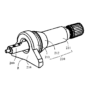
Embodiment 1
As shown in FIG. 2A, the core rod 200 is a rigid body, such as metal. The core
rod 200 is covered with an elastomer 210, which can be divided into an
elastomer
mouth 211 near the valve stem filling hole, an elastomer middle section 212
and an
elastomer end section 213 near the wheel rim hole 310. In the protruding part
of the
valve stem of this embodiment, a supporting part 214 is added on the elastomer
end
section 213, and the supporting part 214 can be integrally formed or fixedly
connected with the elastomer 210. The material of the supporting part 214 can
be the
same as that of the elastomer 210, so as to facilitate one-time molding or
fixed
connection, and it can also be other elastic materials.
The elastomer end section 213 of the valve stem can be a hollow cylinder, and
the height of the cylinder is the thickness of the elastomer end section 213
along the
valve stem axis (hereinafter referred to as thickness). The thickness of the
supporting
part 214 is less than or equal to the thickness of the elastomer end section
213. The
middle part of the contact surface between the supporting part 214 and the
wheel rim
300 has a depression R inward along the radial direction of the valve stem, so
that the
supporting part 214 has two supporting feet. Of course, the middle part of the
contact
surface between the supporting part 214 and the wheel rim 300 can also fully
fit with
the supporting part 214 without the depression R.
FIG. 2B is a schematic diagram when this embodiment is mounted on a wheel
rim hole 310. When the valve stem is mounted on the wheel rim hole 310, the
elastomer 210 passes through the wheel rim hole 310 and contacts with the
wheel rim
surface 320 to play the role of sealing and buffering. The core rod 200 is
inserted into
the wheel rim hole 310, the elastomer end section 213 of the elastomer and the
supporting part 214 are both located in the inner plane of the wheel rim hole
310, and
the supporting part 214 is supported on the wheel rim surface 320 in the wheel
rim
300, so that the valve stem will not rotate during the driving of the
automobile. When
the valve stem is mounted on the wheel rim hole 310, there is a gap G between
the
8
Date Recue/Date Received 2021-02-18
CA 03109996 2021-02-18
supporting part 214 and the wheel rim surface 320, which plays a certain
buffer role
of the supporting part 214 during the driving of the automobile.
FIG. 2C is a schematic diagram when the valve stem of the present embodiment
and a TPMS transmitter 100 are mounted on the wheel rim hole 310 together.
FIG. 2D
is a cross-sectional view when the valve stem of the present embodiment and a
TPMS
transmitter 100 are mounted in the wheel rim hole 310 together. It can be seen
from
FIG. 2D that the elastomer end section 213 and the supporting part 214 of the
valve
stem are embedded in the wheel rim hole 310, and the bottom of the TPMS
transmitter 100 contacts the wheel rim surface 320.
The beneficial effect of this embodiment is that when the TPMS transmitter 100
is lifted away from the wheel rim surface 320 in the driving of automobile,
the
supporting part 214 of the valve stem will not be lifted away from the wheel
rim
surface 320 and still play a supporting role, which prevents the TPMS
transmitter 100
from rotating around the axial direction of the core rod 200; because this
embodiment
adds the supporting part 214 to the elastomer end section 213 of the
conventional
valve stem, the mounting method is basically the same as that of the
conventional
buckled valve stem, which can be pulled in or pushed in for direct replacement
with
the conventional valve stem; due to the addition of the supporting part 214,
the
mounting direction of the TPMS transmitter 100 is limited, which can ensure
that the
TPMS transmitter 100 will not be biased when it is mounted on the wheel rim
300,
and can effectively reduce the risk of loss of function or reduction in
performance of
the TPMS transmitter 100 due to the biased or backward mounting of the TPMS
transmitter 100.
Embodiment 2
FIG. 3A shows another embodiment of the present invention. In this embodiment,
a
supporting member 400 is sheathed at the end of the core rod 200 near the
mounting
position of the TPMS transmitter 100. The middle part of the supporting member
400 is
provided with a hole 410 matched with the shape of the end of the core rod
200. For
example, the end of the core rod 200 is made into a flat square structure,
which has two
9
Date Recue/Date Received 2021-02-18
CA 03109996 2021-02-18
opposite planes, the upper surface 220 and the lower surface 230 from the
perspective of
the figure. The shape of the hole 410 in the middle of the supporting member
400 matches
the flat square structure at the end of the core rod 200, so that the end of
the core rod 200
can just pass through the hole 410 in the middle of the supporting member 400
and engage
with it. It can be understood that the embodiment of the invention does not
limit the end of
the core rod 200 to be a flat square structure, as long as the matching shape
of the end of
the core rod and the supporting member can prevent the two from relative
rotation. The
supporting member 400 includes two supporting feet 421 and 422, which are
connected
with the middle part of the supporting member 400 through the supporting rods
431 and
432 respectively, and the angle between the supporting feet 421 , 422 and the
supporting
rods 431, 432 is greater than or equal to 90 degrees. The supporting feet 421,
422, the
supporting rods 431,432 and the middle part of the supporting member 400 are
integrally
formed or fixedly connected. The material of the supporting member 400 in this
embodiment can be rigid, such as metal or plastic.
As shown in FIG. 3B, when the valve stem is mounted in the wheel rim hole 310,
the
supporting feet 421 and 422 of the supporting member 400 contact the wheel rim
surface
320 of the wheel rim 300 to support. FIG. 3C is a schematic diagram when the
valve stem
of this embodiment and TPMS transmitter 100 are mounted on the wheel rim hole
310
together. As shown in FIG. 3C, the supporting function of the supporting feet
421 and 422
can prevent the TPMS transmitter 100 fixed to it from rotating relative to the
axis of the
valve stem even if it is lifted away from the wheel rim surface 320.
The beneficial effect of this embodiment is that the structure of the valve
stem itself
does not need to be changed, but only an accessory is added to the original
structure,
which is easy to mount; the distance between the two supporting feet 421 and
422 of the
supporting member 400 is greater than the gap G between the supporting part
214 and the
wheel rim surface 320 in the first embodiment, and the distance between the
supporting
feet not only serves a buffering function in the driving of the automobile,
but also has
stronger stability.
Embodiment 3
Date Recue/Date Received 2021-02-18
CA 03109996 2021-02-18
As shown in FIG. 4A, this embodiment is similar to the first embodiment in
that the
elastomer end section 213 of the valve stem is changed. In this embodiment, at
least one
protruding part is added on the elastomer end section 213 of the valve stem.
The
protruding part is located at a position suitable for contacting with a
sidewall of the wheel
rim in the axial direction of the valve stem. Meanwhile, the sidewall of the
wheel rim is
provided with a concave part matched with the protruding part.
Preferably, in this embodiment, there are two protruding parts 215 and 216.
The
exemplary structure of the two protruding parts 215 and 216 can be a cube
shape,
which is integrally formed or fixedly connected with the elastomer end section
213 of
the valve stem. It can be understood that the above-mentioned shape is only an
example, and the protruding parts 215 and 216 may also be other shapes. The
material
of the protruding parts can be consistent with the elastomer, so as to
facilitate
one-time forming or fixed connection, and it can also be other elastic
materials. The
positions of two examples of the protruding parts are shown in FIG. 4A, and
their
connecting line is parallel to the wheel rim surface. The two protruding parts
215 and
216 are symmetrically distributed on the outer circumference of the elastomer
end
section 213 of the valve stem. Correspondingly, as shown in FIG. 4B, the wheel
rim
hole 310 of the wheel rim is provided with concave parts 311 and 312 matched
with
the protruding part, and the size and position of the concave parts are
adapted to the
protruding parts 215 and 216, so that the elastomer end section 213 with the
protruding part can be inserted into the wheel rim hole 310 with the concave
part.
In other embodiments, there may be two or more protruding parts uniformly or
non-uniformly distributed on the outer circumference of the elastomer end
section
213 of the valve stem. Correspondingly, the wheel rim hole 310 of the wheel
rim is
also provided with concave part matched with the number, size and position of
the
protruding part.
FIG. 4C is a schematic diagram when the embodiment is mounted on the wheel
rim hole 310. The valve stem just fits on the wheel rim hole 310 to prevent
the valve
stem from rotating.
11
Date Recue/Date Received 2021-02-18
CA 03109996 2021-02-18
FIG. 4D is a schematic diagram when the embodiment and TPMS transmitter
100 are mounted on the wheel rim hole 310 together.
The beneficial effect of the present embodiment is similar to that of the
first
embodiment.
Embodiment 4
As shown in FIG. 5A, in this embodiment, two protruding parts 510 and 520 are
arranged on the wheel rim surface 320. The protruding part is rectangular and
is fixed
along the radial direction of wheel rim 300. The bottom of the protruding part
is in
contact with the wheel rim surface 320, and the contact part between the
protruding
part and the side surface where the wheel rim hole 310 is located has an arc
fitting
with the part. The two protruding parts are respectively located on both sides
of the
wheel rim hole 310, and their spacing is adapted to the size of the TPMS
transmitter
100, so that the two protruding parts 510 and 520 can contact with the TPMS
transmitter 100 to hold it, as shown in FIG. 5B. When the automobile is
driving, the
two protruding parts 510 and 520 can counteract the rotational torque produced
by
the eccentricity and centrifugal force of the transmitter 100, so as to ensure
that the
TPMS transmitter 100 in operation does not rotate and operates stably. The
height of
the protruding part should ensure that when the TPMS transmitter 100 is lifted
away
from the wheel rim surface 320, it will not exceed the two protruding parts.
In this
embodiment, the material of the protruding part can be elastic material, such
as
rubber, or rigid material, such as metal.
Embodiment 5
As shown in FIG. 6A, in this embodiment, on the basis of the fourth
embodiment, two protruding parts 510 and 520 set on the wheel rim surface 320
are
added with one stop block 511 and 521 respectively. The stop blocks 511 and
521 are
respectively located on the side surfaces of the protruding parts 510 and 520
facing
the wheel rim hole 310, and their positions are in the middle or high part of
the side.
As shown in FIG. 6B, when the TPMS transmitter 100 is mounted in the wheel rim
hole 310, the stop blocks 511 and 521 just stuck on both sides of the TPMS
transmitter
12
Date Recue/Date Received 2021-02-18
CA 03109996 2021-02-18
100. The position and shape of the stop blocks 511 and 521 are set to limit
the lifting
height of the TPMS transmitter 100 when it is lifted off the wheel rim due to
eccentricity and centrifugal force when the automobile is driving. Preferably,
the
structure of the stop blocks 511 and 521 and the setting of their positions
prevent the
TPMS transmitter 100 from being lifted away from the wheel rim during the
driving
of the automobile, so that the position will not shift. As shown in FIG. 6A,
the
exemplary structures of the stop blocks 511 and 521 may be cube shaped, and in
other
embodiments, they may also be other shapes.
Embodiment 6
As shown in FIG. 7A, in this embodiment, on the basis of the fourth
embodiment, two grooves 512 and 522 are respectively added on the two
protruding
parts 510 and 520 set on the wheel rim surface 320. The grooves 512 and 522
are
respectively located on the side surfaces of the protruding parts 510 and 520
facing
the wheel rim hole 310, and their positions are at the middle and high parts
of the side.
As shown in FIG. 7B, when the TPMS transmitter 100 is mounted in the wheel rim
hole 310, the most protruding parts on both sides of the body of the TPMS
transmitter
100 can be inserted into the grooves 512 and 522. The positions, depths and
widths of
the grooves 512 and 522 are set to limit the lifting height of the TPMS
transmitter 100
when it is lifted off the wheel rim due to eccentricity and centrifugal force.
Preferably,
the positions, widths and depths of the grooves 512 and 522 are set so that
the TPMS
transmitter 100 will not be lifted away from the wheel rim during the driving
of the
automobile, so that the position will not shift. As shown in FIG. 7A, the
exemplary
structures of the grooves 512 and 522 may be rectangular grooves, or other
shapes in
other embodiments.
Embodiments 4, 5 and 6 have the advantages of simple structure, convenient
processing and low cost.
In the above embodiments of the present invention, the material of the
elastomer
is usually rubber.
13
Date Recue/Date Received 2021-02-18
CA 03109996 2021-02-18
FIGs. 8A and 8B are structural diagrams of the assembling structure of the
TPMS transmitter according to an embodiment of the present invention.
Referring to
FIGs. 8A and 8B, the assembling structure includes the fixing structure in the
above
embodiments. The fixing structure includes a valve stem and, for example, a
supporting part 214 in the first embodiment, a supporting part 400 in the
second
embodiment, the protruding parts 215 and 216 integrally formed or fixedly
connected
with the elastomer end section 213 of the valve stem in the third embodiment,
the
concave parts 311 and 312 on the wheel rim hole 310, the two protruding parts
510
and 520 on the wheel rim surface 320 in the fourth embodiment, etc. Combining
with
FIG. 2D, the fixing structure shown in FIGs. 8A and 8B is similar to the
supporting
part 214 as the fixing structure in the first embodiment. However, FIGs. 8A
and 8B
are only examples and are not used to limit the structure of the fixing
structure
included in the assembling structure of the present invention.
Referring to FIGs. 8A and 8B, the assembling structure further includes a
transmitter 100, which is assembled with the fixing structure. The fixing
structure of
TPMS transmitter is located on the inner side of wheel rim 300, that is, the
side where
the transmitter 100 is located. The core rod 200 of the valve stem passes
through the
wheel rim hole 310 and extends out of the wheel rim 300, so a part of the core
rod 200
is located on the outside of the wheel rim 300, that is, the side opposite to
the side
where the transmitter 100 is located.
FIG. 8A is used to show the overall assembling state of the TPMS transmitter
when the assembling structure of the present invention is not adopted. As
shown in
FIG. 8A, in this example, the overall center of gravity position 810 of the
transmitter
100 and the fixing structure is located on the inner side of the wheel rim
300. During
the operation of the automobile, the wheel rim rotates, and the centrifugal
force on
the transmitter and the fixing structure causes the center of gravity move
away from
the center of the wheel rim. Since the overall center of gravity position 810
of the
transmitter 100 and the fixing structure is located on the inner side of the
wheel rim
300, when the overall center of gravity position 810 moves away from the
center of
14
Date Recue/Date Received 2021-02-18
CA 03109996 2021-02-18
gravity of the wheel rim, the transmitter 100 and the fixing structure on the
inner side
of the wheel rim 300 may move up and away from the wheel rim surface,
resulting in
the fixing structure of the TPMS transmitter losing the fixed effect on the
TPMS
transmitter. For example, for the first embodiment, the supporting part 214
may move
upward away from the wheel rim surface 320; for the second embodiment, the
supporting feet 421 and 422 may move upward away from the wheel rim surface
320.
When the fixing structure of TPMS transmitter cannot play a fixed role, the
transmitter 100 may rotate or move, thus affecting its performance.
FIG. 8B is used to show the overall assembling state of the TPMS transmitter
when adopting the assembling structure of the present invention. As shown in
FIG.
8B, according to the assembling structure of the present invention, when the
transmitter 100 and the fixing structure are assembled together, the overall
center of
gravity position 820 of the transmitter 100 and the fixing structure is
located at a part
of the valve stem outside the wheel rim 300. During the operation of the
automobile,
the wheel rim rotates, and the centrifugal force on the transmitter 100 and
the fixing
structure causes the center of gravity move away from the center of the wheel
rim.
Since the overall center of gravity position 820 of transmitter 100 and fixing
structure
is located on the outside of wheel rim 300, when the center of gravity moves
outward,
the part of the valve stem outside the wheel rim 300 will move upward under
centrifugal force, accordingly, the transmitter 100 inside the wheel rim 300
will
move downward, so as to be more close to the wheel rim surface, thus
strengthening
the supporting and fixing function of the fixing structure.
In this embodiment, when designing the fixing structure, the overall center of
gravity position 820 of the transmitter 100 and the fixing structure can be
located at a
part of the valve stem located outside the wheel rim 300 through selection of
its
structure and material. For example, the end of the core rod 200 of the valve
stem is
usually made of metal material, so for the first and second embodiments,
lighter
materials can be used for the supporting part 214 and the supporting feet 421
and 422.
For the third to sixth embodiments, although the fixing structure itself can
play a
Date Recue/Date Received 2021-02-18
CA 03109996 2021-02-18
good role of fixing the transmitter 100, the embodiment shown in FIG. 8B can
also be
applied to these embodiments to further avoid the transmitter lifting off the
wheel rim
surface.
Unless it is clearly stated in the claim, the sequence of processing elements
and
sequences, the use of numbers and letters, or the use of other names in the
application
are not used to limit the sequence of the application process and method.
Although
some embodiments of the invention that are currently considered useful are
discussed
through various examples in the above disclosure, it should be understood that
such
details are only for the purpose of illustration, and the additional claims
are not
limited to the disclosed embodiments. On the contrary, the claims are intended
to
cover all modifications and equivalent combinations that conform to the
essence and
scope of the embodiments of the present application.
The present application uses specific words to describe the embodiments of the
present application. For example, "an embodiment", "one embodiment", and / or
"some embodiments" mean a certain feature, structure or feature related to at
least
one embodiment of the present application. Therefore, it should be emphasized
and
noted that "an embodiment" or "one embodiment" or "an alternative embodiment"
mentioned twice or more in different positions in this specification do not
necessarily
refer to the same embodiment. In addition, some features, structures or
features in
.. one or more embodiments of the present application may be appropriately
combined.
Similarly, it should be noted that in order to simplify the disclosure of this
application and help understand one or more application embodiments, in the
previous description of the application embodiments, multiple features are
sometimes incorporated into one embodiment, drawings or the description
thereof.
However, this disclosure method does not mean that the application object
needs
more features than those mentioned in the claims. In fact, the features of the
embodiment are less than all the features of the single embodiment disclosed
above.
Although the invention has been described with reference to the current
specific
embodiments, ordinary technicians in the technical field should realize that
the above
16
Date Recue/Date Received 2021-02-18
CA 03109996 2021-02-18
embodiments are only used to describe the invention, and various equivalent
changes
or substitutions can be made without departing from the spirit of the
invention.
Therefore, as long as the changes and variations of the above embodiments are
within
the scope of the essence of the present invention, they will fall within the
scope of the
claims of this application.
17
Date Recue/Date Received 2021-02-18