Note: Descriptions are shown in the official language in which they were submitted.
CA 03110401 2021-02-22
WO 2020/047385 PCT/US2019/049020
COLLAPSIBLE STRUCTURAL FRAME SYSTEM FOR A SHEET-LIKE BUILDING
MATERIAL
CROSS-REFERENCE TO RELATED APPLICATIONS
[0001] This application is a PCT International Application of U.S. Provisional
Patent Application
No. 62/725,611 filed on August 31, 2018. The disclosure of the above
application is incorporated
herein by reference.
FIELD
[0001] The present invention relates to building systems. Particular
embodiments of the invention
relate to collapsible systems for forming the structure of a soffit or similar
framework. Particular
embodiments provide the structure for holding drywall or other sheet-like
finish material.
BACKGROUND
[0002] Many office buildings and other buildings have interior designs that
include areas of flat
ceilings and walls. Some of these buildings also include soffits or other
features that include
multiple angles between relatively small flat areas. For example, an upper
area of an occupiable
building space at the junction between a wall and the ceiling can include a
rectangular (or other
shape) boxed out area having a vertical surface sometimes referred to as a
facia and a horizontal
surface that is known as a soffit. A structure is traditionally built and then
drywall or some other
building material (often a sheet material) is fastened to the structure.
[0003] A problem exists in that traditionally the structure of the soffit and
facia is stick-built by a
worker in the field from wood or metal studs or other stock pieces that need
to be custom cut and
fitted. This procedure is time consuming and requires significant care to
ensure that all the
appropriate angles and lengths are identical so that a uniform structure
results.
[0004] Accordingly, embodiments of the invention provide a system for quickly
and easily
constructing a dimensionally uniform structural framework for a flat area,
soffit, fascia, or other
building area.
- 1 -
CA 03110401 2021-02-22
WO 2020/047385 PCT/US2019/049020
SUMMARY
[0005] Embodiments of the invention provide a solution to the above problem by
allowing more
flexibility in grid design and more flexibility in ceiling tile construction
and arrangement.
[0006] In one aspect, a collapsible structural frame is provided that is
configured to provide a
structure to which building material sheets are attached to form a surface.
The frame includes a
first frame portion that corresponds to a first portion of the surface and is
configured to receive a
first sheet of the building material; a second frame portion that corresponds
to a second portion of
the surface and is configured to receive a second sheet of the building
material; a pivoting
mechanism that attaches the second frame portion to the first frame portion
and has a pivoting
axis, the pivoting mechanism permitting the second frame portion to rotate
about the pivoting axis
relative to the first frame portion, and the pivoting mechanism permitting the
second frame portion
to rotate about the pivoting axis from an undeployed state to a deployed
state; and a locking
mechanism that fixes a relative position of the first frame portion and the
second frame portion in
the deployed state. The undeployed state is a folded state compared to the
deployed state.
[0007] Other embodiments of the present invention include a building system
comprising the
previously discussed collapsible structure frame in the deployed state.
[0008] In another aspect, a collapsible structural frame is provided that is
configured to provide a
soffit structure to which building material sheets are attached to form a
first soffit surface and a
second soffit surface. The frame includes a first frame portion that
corresponds to the first soffit
surface and is configured to receive a first sheet of the building material; a
second frame portion
that corresponds to the second soffit surface and is configured to receive a
second sheet of the
building material; a pivoting mechanism that attaches the second frame portion
to the first frame
portion and has a pivoting axis, the pivoting mechanism permitting the second
frame portion to
rotate about the pivoting axis relative to the first frame portion, and the
pivoting mechanism
permitting the second frame portion to rotate about the pivoting axis from an
undeployed state to
a deployed state; and a locking mechanism that fixes a relative position of
the first frame portion
and the second frame portion in the deployed state at a deployed angle. The
undeployed state is a
folded state compared to the deployed state, and the deployed angle is more
than 0 degrees and
less than 180 degrees.
[0009] In another aspect, a collapsible structural soffit frame is provided to
which a building
material sheet is attached to form a soffit surface. The frame includes a
first rigid member; a
- 2 -
CA 03110401 2021-02-22
WO 2020/047385 PCT/US2019/049020
second rigid member; a first collapsible member that connects the first rigid
member to the second
rigid member, the first collapsible member having a collapsed position and a
deployed position;
and a second collapsible member that connects the first rigid member to the
second rigid member,
the second collapsible member having a collapsed position and a deployed
position. In the
deployed position of both the first and second collapsible members the first
and second collapsible
members are structural members configured to support the building material
sheet.
[0010] Other embodiments of the present invention include a building system
comprising the
previously discussed collapsible structure soffit frame in the deployed state.
[0011] Other embodiments of the present invention include a method of
installing a soffit
comprising: a) providing a collapsible structural frame in a folded state, the
collapsible structural
frame configured to provide a structure to which building material sheets are
attached to form a
surface; b) converting the collapsible structural frame from the folded state
to a deployed state and
fastening the collapsible structural frame to a preexisting support; and c)
fastening at least a sheet
of building material to the surface of the collapsible structural frame.
[0012] Further areas of applicability of the present invention will become
apparent from the
detailed description provided hereinafter. It should be understood that the
detailed description and
specific examples, while indicating preferred embodiments of the invention,
are intended for
purposes of illustration only and are not intended to limit the scope of the
invention.
BRIEF DESCRIPTION OF THE DRAWINGS
[0013] The present invention will become more fully understood from the
detailed description and
the accompanying drawings, wherein:
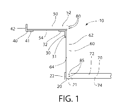
[0014] FIG. 1 is a side view of a conventional soffit structure;
[0015] FIG. 2 is a perspective view of the structure of FIG. 1;
[0016] FIG. 3 is a top view of the structure of FIG. 1;
[0017] FIG. 4 is top view of a first embodiment of the invention in an
unfolded state;
[0018] FIG. 5 is a detail view of the embodiment shown in FIG. 4 in a folded
state;
[0019] FIG. 6 is a side view of a soffit system in accordance with exemplary
embodiments of the
invention in a deployed state;
[0020] FIG. 7 is a side view of the embodiment shown in FIG. 6 in a flat, non-
deployed state;
- 3 -
CA 03110401 2021-02-22
WO 2020/047385 PCT/US2019/049020
[0021] FIG. 8 is a side view of a holding mechanism in accordance with
exemplary embodiments
of the invention;
[0022] FIG. 9 is a side view of the soffit system of FIG. 6 in an alternate
deployed state;
[0023] FIG. 10 is a side view of the soffit system of FIG. 6 in an alternate
deployed state;
[0024] FIG. 11 is a side view of the soffit system of FIG. 6 in an alternate
deployed state;
[0025] FIG. 12 is a top view of a soffit system in accordance with exemplary
embodiments of the
invention in a folded, non-deployed state;
[0026] FIG. 13 is a top view of the soffit system of FIG. 12 in a deployed
state; and
[0027] FIG. 14 is a perspective view of an occupiable building space having a
soffit structure using
the soffit system of FIG. 12.
[0028] All drawings are schematic and not necessarily to scale. Parts given a
reference numerical
designation in one figure may be considered to be the same parts where they
appear in other figures
without a numerical designation for brevity unless specifically labeled with a
different part number
and described herein.
DETAILED DESCRIPTION
[0029] The following description of the preferred embodiment(s) is merely
exemplary in nature
and is in no way intended to limit the invention, its application, or uses.
[0030] In the description of embodiments disclosed herein, any reference to
direction or
orientation is merely intended for convenience of description and is not
intended in any way to
limit the scope of the present invention. Relative terms such as "lower,"
"upper," "horizontal,"
"vertical,", "above," "below," "up," "down," "top" and "bottom" as well as
derivative thereof
(e.g., "horizontally," "downwardly," "upwardly," etc.) should be construed to
refer to the
orientation as then described or as shown in the drawing under discussion.
These relative terms
are for convenience of description only and do not require that the apparatus
be constructed or
operated in a particular orientation. Terms such as "attached," "connected,"
"coupled,"
"interconnected," and similar refer to a relationship wherein structures are
secured or attached to
one another either directly or indirectly through intervening structures, as
well as both movable or
rigid attachments or relationships, unless expressly described otherwise. The
term "fixed" refers
to two structures that cannot be separated without damaging one of the
structures. The term
"filled" refers to a state that includes completely filled or partially
filled.
- 4 -
CA 03110401 2021-02-22
WO 2020/047385 PCT/US2019/049020
[0031] As used throughout, ranges are used as shorthand for describing each
and every value that
is within the range. Any value within the range can be selected as the
terminus of the range. In
addition, all references cited herein are hereby incorporated by reference in
their entireties. In the
event of a conflict in a definition in the present disclosure and that of a
cited reference, the present
disclosure controls.
[0032] Figure 1 shows an example of a traditional building structure for
supporting drywall panels
to form a soffit and facia. The thickness of some members in the figures is
not to scale and are
made thicker in proportion to other members for clarity. Actual members may be
relatively thin
sheet metal or other material such as wood, plastic, composite or other
material.
[0033] In Figure 1, a structural frame 10 includes an upper horizontal section
formed by members
50, a vertical section formed by members 60 and a lower horizontal section
formed by members
70. In this example, the upper horizontal section and the vertical section
intersect at a right angle,
and the vertical section and the lower horizontal section intersect at a right
angle. In other
examples, different angles exist between the particular sections and the
sections have different
relative lengths. Members 50, 60, 70 are, in this example, longitudinal
members having a "T"
shaped cross section. Angles 20, 30, 40 are, in this example, longitudinal
members having an "L"
shaped cross section. Although Figures 1-3 show surfaces 54, 64, 74 being
offset from surfaces
21, 22, 31, 32, 41, 42 by the thickness of angles 20, 30, 40, other examples
are fabricated so that
surfaces 54, 64, 74 are flush with surfaces 21, 22, 31, 32, 41, 42. In this
example, member 50 is
fixed to member 60 by two screws 80, and member 60 is fixed to member 70 by
two screws 85.
[0034] The structural frame 10 may comprise a first frame portion that may
form a first portion of
the surface and is configured to receive a first sheet of the building
material. The first frame
portion may comprise a first longitudinal member 50 and a second longitudinal
member 40, the
first longitudinal member 50 arranged orthogonal to the second longitudinal
member 40.
[0035] The structural frame 10 may further comprise a first pivoting mechanism
80 that attaches
the second frame portion to the first frame portion and has a first pivoting
axis. The first pivoting
mechanism 80 may permit the second frame portion to rotate about the first
pivoting axis relative
to the first frame portion, and the first pivoting mechanism 80 permitting the
second frame portion
to rotate about the first pivoting axis from an undeployed state to a deployed
state. The undeployed
state may be a folded state compared to the deployed state.
- 5 -
CA 03110401 2021-02-22
WO 2020/047385 PCT/US2019/049020
[0036] The structural frame 10 may further comprise a first locking mechanism
that fixes a relative
position of the first frame portion and the second frame portion in the
deployed state.
[0037] The first longitudinal member 50 may have a T-shaped cross-section. The
T-shaped cross-
section of the first longitudinal member 50 may comprise a bottom flange 54
that forms part of the
first portion of the surface.
[0038] The second longitudinal member 40 may have an L-shaped cross-section.
The L-shaped
cross-section of the second longitudinal member 40 may comprise a bottom
flange 64 that forms
part of the first portion of the surface.
[0039] The second longitudinal member 40 of the first frame portion may
extends along a direction
that is substantially parallel to the first pivoting axis.
[0040] The structural frame 10 may comprise a second frame portion may form a
second portion
of the surface and is configured to receive a second sheet of the building
material. The second
frame portion may comprise a third longitudinal member 60 and a fourth
longitudinal member 20,
the third longitudinal member 60 arranged orthogonal to the fourth
longitudinal member 20.
[0041] The third longitudinal member 60 may have a T-shaped cross-section. The
T-shaped cross-
section of the third longitudinal member 60 may comprise a bottom flange 64
that forms part of
the first portion of the surface.
[0042] The fourth longitudinal member 20 may have an L-shaped cross-section.
The L-shaped
cross-section of the fourth longitudinal member 20 may comprise a bottom
flange 22 that forms
part of the first portion of the surface.
[0043] The fourth longitudinal member 20 of the second frame portion may
extends along a
direction that is substantially parallel to the first pivoting axis.
[0044] The structural frame 10 may comprise a third frame portion that
corresponds to a third
portion of the surface and is configured to receive a third sheet of the
building material. The third
frame portion may comprise a fifth longitudinal member 70. The fifth
longitudinal member 70
may be arranged orthogonal to the fourth longitudinal member 20.
[0045] The structural frame 10 may further comprise a second pivoting
mechanism 85 that
attaches the third frame portion to the second frame portion and has a second
pivoting axis. The
second pivoting mechanism 85 may permit the second frame portion to rotate
about the second
pivoting axis relative to the third frame portion, and the second pivoting
mechanism 85 may
- 6 -
CA 03110401 2021-02-22
WO 2020/047385 PCT/US2019/049020
permitting the second frame portion to rotate about the second pivoting axis
from an undeployed
state to a deployed state.
[0046] The structural frame 10 may further comprise a second locking mechanism
that fixes a
relative position of the second frame portion and the third frame portion in
the deployed state.
[0047] The fifth longitudinal member 70 may comprise a T-shaped cross-section.
The T-shaped
cross-section of the fifth longitudinal member 70 may comprises a bottom
flange 74 that forms
part of the third portion of the surface.
[0048] The fifth longitudinal member 70 of the third frame portion may extends
along a direction
that is substantially orthogonal to the second pivoting axis.
[0049] Figure 2 is a perspective view of frame 10 and Figure 3 is a top view
of frame 10. These
figures help illustrate the stick-built nature of this example of a
traditional building structure for
supporting drywall panels.
[0050] Figures 4 and 5 show an example of an embodiment of the invention that
simplifies the
work needed in the field to create a frame for supporting drywall or other
sheet-like material. In
this example, framework 100 has two panels 200, 300 that are hinged at a
folding line 150 such
that panels 200, 300 can be folded into a condition in which panel 200 is
positioned on top of panel
300, as shown in Figure 5. This example provides a frame that can be
constructed off-site and
then quickly and easily unfolded on-site to provide a dimensionally correct
framework.
[0051] The sheet-like material may be formed from a first sheet of the
building material and a
second sheet of the building material. The first sheet and the second sheet
may be two completely
separate sheets of material. In another embodiment, the first and second
sheets may be formed
from a single panel of building material, whereby the single panel has a V-
shaped cut formed into
one of the major surfaces, thereby allowing the single panel to be folded to a
shape conforming to
a first frame portion and a second frame portion of the frame, whereby the
singe panel extends
continuously from the first frame portion to the second frame portion. The V-
shaped cut may be
formed such that a 90 degree fold is formed on the single panel. Other fold
angles may range from
30 to 170 degrees ¨ including all angles and subranges there-between.
[0052] Panel 200 has a longitudinal member 210 and a parallel longitudinal
member 215 that
establish the length of panel 200. Two end transverse members 220 bridge
between longitudinal
members 210, 215. In this example, two interior transverse members 230 are
parallel to end
- 7 -
CA 03110401 2021-02-22
WO 2020/047385 PCT/US2019/049020
transverse members 220 and bridge between longitudinal members 310, 315.
Similarly to panel
200, panel 300 has a longitudinal member 310 and a parallel longitudinal
member 315 that
establish the length of framework panel 300. Two end transverse members 320
bridge between
longitudinal members 310, 315. In this example, two interior transverse
members 330 are parallel
to end transverse members 320 and bridge between longitudinal members 310,
315.
[0053] Figure 5 shows framework 100 in a folded state where panel 200 is
rotated relative to panel
300 about folding line 150 such that panel 200 is positioned on top of panel
300. The movement
of panel 200 relative to panel 300 can be controlled by one or move hinging
mechanisms. The
hinging mechanism can be located at folding line 150 and be a simple hinge, or
they can be located
remotely from folding line 150 and/or be some other type of mechanism that
permits the desired
relative movement of panels 200, 300. The hinging mechanism can be configured
to allow relative
rotation of the panels 200, 300 through any angle of rotation. For example, as
shown in Figure 4,
panels 200, 300 can rotate to a position at which they are 180 degrees from
each other. In other
examples, panels 200, 300 can rotate to a position in which they are more or
less than 180 degrees
from each other. For example, in the case of a common soffit in a building
space (or other
application), panels 200, 300 can be moved to a position in which they are 90
degrees from one
another.
[0054] One or more locking mechanisms can be provided to lock panels 200, 300
in a desired
position relative to one another. Such locking mechanisms can be of any
configuration that
securely holds the panels in the desired position sufficiently to allow the
attachment of the drywall,
or other, building panels. Figures 6-11 show an example of locking mechanisms
in accordance
with the invention.
[0055] Figure 6 shows an example of a framework 600 in accordance with
embodiments of the
invention. Framework 600 has an upper member 700 that is T-shaped in cross-
section. The T-
shaped cross-section is formed by a rib portion 710 and a flange portion 720
that extends laterally
away from rib portion 710 on both sides of rib portion 710. While upper member
700 is shown as
a T-shaped member in this example, in other examples upper member 700 has an L-
shaped cross-
section, a box-shaped cross-section, or another shaped cross-section. Any
appropriately shaped
cross-section can be used as long as it is sufficiently strong to support the
drywall or other building
sheet that is to be attached to framework 600.
- 8 -
CA 03110401 2021-02-22
WO 2020/047385 PCT/US2019/049020
[0056] Framework 600 has a middle member 800 that is attached to upper member
700 by a
swiveling joint 805 that can be, for example, a bolt, pin, rivet, or other
swiveling fastener. In this
example, middle member 800 is T-shaped in cross-section. The T-shaped cross-
section is formed
by a rib portion 810 and a flange portion 820 that extends laterally away from
rib portion 810 on
both sides of rib portion 810. While middle member 800 is shown as a T-shaped
member in this
example, in other examples middle member 800 has an L-shaped cross-section, a
box-shaped
cross-section, or another shaped cross-section. Any appropriately shaped cross-
section can be
used as long as it is sufficiently strong to support the drywall or other
building sheet that is to be
attached to framework 600.
[0057] Framework 600 has a lower member 900 that is attached to middle member
800 by a
swiveling joint 806 that can be, for example, a bolt, pin, rivet, or other
swiveling fastener. In this
example, lower member 900 is T-shaped in cross-section. The T-shaped cross-
section is formed
by a rib portion 910 and a flange portion 920 that extends laterally away from
rib portion 910 on
both sides of rib portion 910. While lower member 900 is shown as a T-shaped
member in this
example, in other examples lower member 900 has an L-shaped cross-section, a
box-shaped cross-
section, or another shaped cross-section. Any appropriately shaped cross-
section can be used as
long as it is sufficiently strong to support the drywall or other building
sheet that is to be attached
to framework 600.
[0058] Framework 600 is only one example of a collapsible framework in
accordance with
embodiments of the invention. Other examples have a different number of
members and/or
different shape members and/or a different relative configuration of members.
For example,
instead of three members 700, 800, 900, Framework 600 can have two members or
more than three
members. In some embodiments, members 700, 800, 900 can have different
relative lengths. In
some embodiments, members 700, 800, 900 do not intersect at 90 degree angles.
In some
embodiments members 700 and 800 intersect at a first angle and members 800 and
900 intersect
at a different angle.
[0059] In some embodiments, members 700, 800, 900 can be locked in a
particular relative
position such that they form a particular included angle relative to each
other. For example,
framework 600 is locked into a configuration where upper member 700 and middle
member 800
form a 90 degree angle, and middle member 800 and lower member 900 form a 270
degree angle.
In this example, a locking mechanism includes a first locking member 650, a
pin 730 on upper
- 9 -
CA 03110401 2021-02-22
WO 2020/047385 PCT/US2019/049020
member 700, and a pin 83 ion middle member 800, as well as a second locking
member 670, a pin
832 on middle member 800, and a pin 930 on lower member 900. Locking members
650, 670 are
rigid material such as metal, plastic or composite. Pins 730, 831, 832, 930
are a shoulder bolt
configuration including a head of a diameter A, a large diameter shaft portion
adjacent the head
and having a diameter B that is less than diameter A, and a small diameter
shaft portion adjacent
to the large diameter shaft portion and having a diameter C that is less than
diameter B. A detailed
view of an example of locking member 650, 670 is shown in Figure 8. In this
example, locking
member 650, 670 has a main body 651 in which a longitudinal slot 657 is
located. Longitudinal
slot 657 has an enlarged area 655 at each end of slot 657 for receiving pins
730, 831. The width
in the transverse direction of longitudinal slot 657 is slightly larger than
the small diameter shaft
portion of pins 730, 831, 832, 930, but smaller than the large diameter shaft
portions of pins 730,
831, 832, 930. In this example, locking members 650, 670 are curved to act as
a spring such that
the ends of locking members 650, 670 are urged away from members 700, 800,
900. This urging
action pushes enlarged areas 655 onto the large diameter shaft portion so that
members 700, 800,
900 cannot move relative to each other due to the large diameter shaft
portions not being able to
pass through longitudinal slot 657. In other examples, enlarged areas 655 are
a slight interference
fit with the large diameter shaft portions of pins 730, 831, 832, 930 such
that a user can force
enlarged areas 655 of locking members 650, 670 onto the large diameter shaft
portions of pins
730, 831, 832, 930 to lock locking members 650, 670 in a position that
prevents relative movement
of members 700, 800, 900.
[0060] Figure 7 shows frame 600 in a flat condition that can be used for
shipping. Once on the
jobsite, frame 600 can be folded to the desired configuration to act as a
support for a soffit or other
building surface. To provide the deployed configuration shown in Figure 6,
upper member 700 is
rotated in the direction of Arrow A to a position in which upper member 700
forms a 90 degree
angle with middle member 800, and lower member 900 is rotated in the direction
of Arrow B to a
position in which lower member 900 forms a 270 degree angle with middle member
800.
[0061] The example shown in Figure 6 uses locking members 650, 670 of a given
length that result
in frame 600 having included angles of 90 degrees and 270 degrees. Using
locking members of
other lengths results in different angles between members 700, 800, 900.
[0062] Figure 9 shows an example where the frame 600 of Figure 7 is deployed
such that upper
member 700 forms a 135 degree angle with middle member 800 and middle member
800 forms a
- 10 -
CA 03110401 2021-02-22
WO 2020/047385 PCT/US2019/049020
225 degree angle with lower member 900. This configuration is the result of
locking member 650
being shorter in the longitudinal direction than the locking member 650 shown
in Figure 6, and
locking member 670 being longer in the longitudinal direction than the locking
member 670 shown
in Figure 6.
[0063] Figure 10 shows an example where the frame 600 of Figure 7 is deployed
such that upper
member 700 forms a 45 degree angle with middle member 800 and middle member
800 forms a
315 degree angle with lower member 900. This configuration is the result of
locking member 650
being longer in the longitudinal direction than the locking member 650 shown
in Figure 6, and
locking member 670 being shorter in the longitudinal direction than the
locking member 670
shown in Figure 6.
[0064] Figure 11 shows an example where the frame 600 of Figure 7 is deployed
such that upper
member 700 forms a 90 degree angle with middle member 800 and middle member
800 forms a
225 degree angle with lower member 900. This configuration is the result of
locking member 650
being the same length in the longitudinal direction than the locking member
650 shown in Figure
6, and locking member 670 being longer in the longitudinal direction than the
locking member 670
shown in Figure 6.
[0065] Although Figures 6 and 8-11 show various deployed configurations, it is
noted that any
number of deployed configurations are possible using locking members of
different lengths. In
addition, fewer or more than three members 700, 800, 900 can be used to form
different shaped
structures. In some cases, a 180 degree angle can be provided between two
adjacent members to
for a flat section in the structure.
[0066] Figures 12-14 show another embodiment of the invention that involves
collapsible
members within a flat panel structure. Figure 12 shows a framework 1000 having
two rigid
members 1010, 1020. Rigid members 1010, 1020 are attached to each other by two
collapsible
members, each having a first member 1030 (also referred to as a "first
portion") and a second
member 1040 (also referred to as a "second portion"). First member 1030 is
pivotably attached to
second member 1040 by a pin 1050 (also referred to as a "first pin" 1050).
First member 1030 is
pivotably attached to rigid member 1010 by a pin 1052 (also referred to as a
"second pin" 1052),
and second member 1040 is pivotably attached to rigid member 1020 by a pin
1054 (also referred
to as a "third pin" 1054).
- 11-
CA 03110401 2021-02-22
WO 2020/047385 PCT/US2019/049020
[0067] Figure 12 is an example of framework 1000 in a collapsed state where
the collapsible
members are folded so that rigid members 1010 and 1020 are relatively close to
each other. This
collapsed state can be preferable for transport to the job site. Figure 13
shows framework 1000 is
a deployed state where rigid members 1010 and 1020 are at a maximum distance
apart. The state
shown in Figure 13 is just one of many possible deployed states. For example,
a deployed state
between that shown in Figure 12 and that shown in Figure 13 can also be used.
Further, the state
shown in Figure 12 can be a deployed state and a state in which rigid members
1010, 1020 are
closer together, or even touching, can be the collapsed state.
[0068] Figure 14 shows and example of two frameworks 1000 installed to form a
soffit and facia
in an occupiable space in a building having a wall W, a ceiling C, and a door
D in wall W. Ceiling
C makes an angle a with wall W at a corner CO. In this case the two frameworks
1000 cover
corner CO with a box structure in which the two frameworks 1000 form a 90
degree angle. The
two frameworks 1000 can be attached to one another and to wall W and ceiling C
using screws,
clips, or some other fastener. In other examples, more than two frameworks
1000 are used. In
other examples, frameworks 1000 are attached to ceiling C, wall W, and/or each
other at angles
other than 90 degrees. In other examples, one framework 1000 is fully deployed
such that first
members 1030 are aligned with second members 1040, and another framework 1000
is partially
deployed such that first members 1030 are not aligned with second members
1040.
[0069] While the foregoing description and drawings represent exemplary
embodiments of the
present disclosure, it will be understood that various additions,
modifications and substitutions
may be made therein without departing from the spirit and scope and range of
equivalents of the
accompanying claims. In particular, it will be clear to those skilled in the
art that the present
invention may be embodied in other forms, structures, arrangements,
proportions, sizes, and with
other elements, materials, and components, without departing from the spirit
or essential
characteristics thereof. In addition, numerous variations in the
methods/processes described herein
may be made within the scope of the present disclosure. One skilled in the art
will further
appreciate that the embodiments may be used with many modifications of
structure, arrangement,
proportions, sizes, materials, and components and otherwise, used in the
practice of the disclosure,
which are particularly adapted to specific environments and operative
requirements without
departing from the principles described herein. The presently disclosed
embodiments are therefore
to be considered in all respects as illustrative and not restrictive. The
appended claims should be
- 12-
CA 03110401 2021-02-22
WO 2020/047385 PCT/US2019/049020
construed broadly, to include other variants and embodiments of the
disclosure, which may be
made by those skilled in the art without departing from the scope and range of
equivalents. In
addition, all combinations of any and all of the features described in the
disclosure, in any
combination, are part of the invention.
- 13 -