Language selection

Search

Patent 3110459 Summary

Third-party information liability

Some of the information on this Web page has been provided by external sources. The Government of Canada is not responsible for the accuracy, reliability or currency of the information supplied by external sources. Users wishing to rely upon this information should consult directly with the source of the information. Content provided by external sources is not subject to official languages, privacy and accessibility requirements.

Claims and Abstract availability

Any discrepancies in the text and image of the Claims and Abstract are due to differing posting times. Text of the Claims and Abstract are posted:

  • At the time the application is open to public inspection;
  • At the time of issue of the patent (grant).
(12) Patent: (11) CA 3110459
(54) English Title: BATTERY SYSTEM FOR HEAVY DUTY VEHICLES
(54) French Title: SYSTEME DE BATTERIE POUR VEHICULES UTILITAIRES LOURDS
Status: Granted and Issued
Bibliographic Data
(51) International Patent Classification (IPC):
  • B60K 01/04 (2019.01)
  • B60L 50/50 (2019.01)
  • B60R 16/04 (2006.01)
(72) Inventors :
  • FORSBERG, CHRIS (Canada)
  • SLOAN, TODD F. (Canada)
  • COUPAL-SIKES, ERIC M. (Canada)
  • VAN HANEGEM, BRAD JONATHAN (Canada)
  • TYERMAN, LANDON (Canada)
(73) Owners :
  • HEXAGON PURUS NORTH AMERICA HOLDINGS INC.
(71) Applicants :
  • HEXAGON PURUS NORTH AMERICA HOLDINGS INC. (United States of America)
(74) Agent: AIRD & MCBURNEY LP
(74) Associate agent:
(45) Issued: 2024-06-18
(86) PCT Filing Date: 2019-08-22
(87) Open to Public Inspection: 2020-02-27
Examination requested: 2021-03-08
Availability of licence: N/A
Dedicated to the Public: N/A
(25) Language of filing: English

Patent Cooperation Treaty (PCT): Yes
(86) PCT Filing Number: PCT/US2019/047773
(87) International Publication Number: US2019047773
(85) National Entry: 2021-02-22

(30) Application Priority Data:
Application No. Country/Territory Date
62/722,758 (United States of America) 2018-08-24

Abstracts

English Abstract

The present disclosure relates to a battery system for a hybrid or an electric vehicle. Another aspect of the present disclosure provides a battery assembly designed for easy and quick exchange of battery assemblies enabling a vehicle to resume driving much more quickly than traditional charging permits.


French Abstract

La présente invention concerne un système de batterie pour un véhicule hybride ou électrique. Un autre aspect de la présente invention concerne un ensemble batterie conçu pour un échange facile et rapide d'ensembles batteries, ce qui permet de reprendre la conduite du véhicule beaucoup plus rapidement que ce qui est possible avec les charges classiques.

Claims

Note: Claims are shown in the official language in which they were submitted.


WHAT IS CLAIMED IS:
1. A battery assembly for an electric vehicle, comprising:
a housing having a first lateral portion, a second lateral portion, and a
central
portion, the housing forming an upwardly oriented recess between the first
lateral
portion and the second lateral portion;
one or more battery units disposed within the housing at least in the central
portion; and
a mounting system disposed at least partially between the first lateral
portion
and the second lateral portion;
wherein a frame member of the electric vehicle can be disposed between the
first lateral portion and the second lateral portion and when so disposed can
be
coupled to the mounting system between the first lateral portion and the
second lateral
portion.
2. The battery assembly of Claim 1, wherein the housing comprises a W-
shaped
housing.
3. The battery assembly of Claim 1, wherein the housing is configured to be
exposed to the road beneath the vehicle when the battery assembly is coupled
to the frame
member of the vehicle.
4. The battery assembly of Claim 1, wherein the mounting system comprises a
first component coupled with the housing and a second component configured to
be coupled
with the frame member, the first component configured to be releasably coupled
to the
second component.
5. The battery assembly of Claim 4, wherein the second component is
configured
to be coupled with a lateral portion of the frame member.
6. The battery assembly of Claim 4, wherein the first component comprises
one
or more brackets disposed on one or both of a first inside surface of the
first lateral portion
and on a second inside surface of the second lateral portion.
7. The battery assembly of Claim 6, wherein the one or more brackets
comprise
one or more U-shaped members configured to be disposed around the second
component of
the mounting system.
8. The battery assembly of Claim 1, wherein at least a portion of the one
or more
battery units is disposed in the first lateral portion and/or the second
lateral portion.
9. The battery assembly of Claim 1, wherein the frame member extends
lengthwise along the vehicle.
-10-
Date Recue/Date Received 2023-07-13

10. The battery assembly of Claim 1, wherein the housing is configured to
be
coupled to the mounting system from beneath the vehicle.
11. A battery assembly for an electric vehicle, comprising:
a housing having a first lateral portion, a second lateral portion, and a
central portion,
the housing feinting a first recess between the first lateral portion and the
central portion, the
first lateral portion, the first recess and the central portion forming a
first bight and a second
recess between the central portion and the second lateral portion, the second
lateral portion,
the second recess and the central portion forming a second bight;
one or more battery units disposed within the central portion of the housing
between
the first bight and the second bight; and
a mounting system disposed at least partially in the first bight and in the
second bight;
wherein a frame member of the electric vehicle can be disposed between the
first
lateral portion and the second lateral portion and when so disposed can be
coupled to the
mounting system between the first lateral portion and the second lateral
portion in or above
one or both of the first recess and the second recess.
12. The battery assembly of Claim 11, wherein the central portion of the
housing
extends to an elevation above a lower portion of the frame member of the
electric vehicle
when the mounting system is coupled with the frame member of the electric
vehicle.
13. The battery assembly of Claim 11, wherein the mounting system comprises
a
plurality of brackets coupled to the housing and positioned to be disposed
laterally of one or
more frame members of the electric vehicle when the battery assembly is
coupled to the
electric vehicle, the one or more frame members of the electric vehicle
including the frame
member of the electric vehicle.
14. The battery assembly of Claim 13, wherein the mounting system
comprises:
a first forward bracket coupled to the housing adjacent to the first lateral
portion and
configured to mount to an outboard side of a first frame rail at a first
location of the first
frame rail;
a first rearward bracket coupled to the housing adjacent to the first lateral
portion and
configured to mount to the outboard side of the first frame rail at a second
location of the first
frame rail rearward of the first location of the first frame rail;
a second forward bracket coupled to the housing adjacent to the second lateral
portion
and configured to mount to an outboard side of a second frame rail at a first
location of the
second frame rail; and
-11-
Date Recue/Date Received 2023-07-13

a second rearward bracket coupled to the housing adjacent to the second
lateral
portion and configured to mount to the outboard side of the second frame rail
at a second
location of the second frame rail rearward of the first location of the second
frame rail.
15. The battery assembly of Claim 14, wherein at least one of the first
forward
bracket and the first rearward bracket is coupled to a side wall of the first
lateral portion of
the housing facing the first recess and at least one of the second forward
bracket and the
second rearward bracket is coupled to a side wall of the second lateral
portion of the housing
facing the second recess.
16. The battery assembly of Claim 14, wherein at least one of the first
forward
bracket, the first rearward bracket, the second forward bracket and the second
rearward
bracket is configured to overlap a surface of another member of the mounting
system in a
direction transverse to a longitudinal axis of the frame member of the
electric vehicle to
which the mounting system is coupled.
17. A method of equipping a vehicle with a battery assembly, comprising:
providing the battery assembly comprising a housing comprising a top side and
a
bottom side, the top side having a central portion that extends upwardly
relative to a recess
disposed between the central portion and a lateral portion of the housing, the
battery
assembly having a housing mounting member coupled therewith at least partially
within the
recess;
positioning the housing below a frame rail of a frame assembly of the vehicle,
the
frame rail having a frame rail mounting member coupled therewith, the frame
rail mounting
member extending transversely to a longitudinal axis of the frame rail;
raising the housing to position the central portion of the housing at least
partially
above a lower surface of a portion of the frame rail extending along the
central portion of the
housing;
positioning the housing mounting member forward or rearward of the frame rail
mounting member such that a surface of the housing mounting member overlaps a
surface of
the frame rail mounting member; and
advancing a fastener through the housing mounting member and the frame rail
mounting member to secure the housing mounting member to the frame rail
mounting
member and thereby to secure the housing to the frame rail.
18. The method of Claim 17, wherein the frame rail is a first frame rail,
the
housing mounting member is one of a first plurality of housing mounting
members coupled to
a first lateral portion of the housing, the frame rail mounting member is one
of a first plurality
-12-
Date Reçue/Date Received 2023-07-13

of frame rail mounting members coupled with a lateral side of the first frame
rail, and further
comprising a second plurality of housing mounting members coupled with a
second lateral
portion of the housing and a second plurality of frame rail mounting members
coupled to a
lateral surface of a second frame rail, the method further comprising:
positioning each of the housing mounting members of the first plurality of
housing
mounting members on a first lateral side of the first frame rail forward or
rearward of a
corresponding one of the frame rail mounting members of the first plurality of
frame rail
mounting members;
positioning each of the housing mounting members of the second plurality of
housing
mounting members on a lateral side of the second frame rail forward or
rearward of a
corresponding one of the frame rail mounting members of the second plurality
of frame rail
mounting members; and
advancing a fastener through corresponding pairs of housing mounting members
and
frame rail mounting members.
19. The method of Claim 17, wherein at least one battery cell located in
the
central portion is disposed above a lower portion of the frame rail following
advancing the
fastener through the housing mounting member and the frame rail mounting
member to
secure the housing mounting member to the frame rail.
20. The method of Claim 17, wherein raising the housing comprises pivotably
coupling a first lateral portion of the housing to a frame portion and
pivoting a second lateral
portion of the housing about an axis disposed through the pivotable coupling.
21. A battery assembly for an electric vehicle, comprising:
a housing having a first lateral portion, a second lateral portion, and a
central portion,
the housing foiming an upwardly oriented recess between the first lateral
portion and the
second lateral portion;
one or more battery units disposed within the central portion of the housing;
and
a mounting system comprising a plurality of brackets attached to an upper
surface of
the housing and disposed at least partially within the upwardly oriented
recess of the housing
between the first lateral portion and the second lateral portion;
wherein a frame member of the electric vehicle can be disposed between the
first
lateral portion and the second lateral portion and when so disposed can be
coupled to the
mounting system between the first lateral portion and the second lateral
portion to suspend
the housing from the frame member of the electric vehicle at a location above
at least a
portion of the upper surface of the housing;
-13-
Date Recue/Date Received 2023-07-13

whereby the one or more battery units is disposed beneath a lower edge of the
frame
member of the vehicle when the battery assembly is coupled with the frame
member.
22. The battery assembly of Claim 21, wherein the housing comprises a W-
shaped
housing.
23. The battery assembly of Claim 21, wherein a continuous expanse of a
side of
the housing from a first lateral side of the first lateral portion to a second
lateral side of the
second lateral portion is configured to be exposed to the road beneath the
electric vehicle
when the battery assembly is coupled to the frame member of the electric
vehicle.
24. The battery assembly of Claim 21, wherein the mounting system comprises
a
first component coupled with the housing and a second component configured to
be coupled
with the frame member, the first component configured to be releasably coupled
to the
second component.
25. The battery assembly of Claim 24, wherein the second component is
configured to be coupled with a lateral portion of the frame member.
26. The battery assembly of Claim 24, wherein the first component comprises
the
plurality of brackets, wherein the plurality of brackets are disposed on one
or both of a first
inside surface of the first lateral portion and on a second inside surface of
the second lateral
portion.
27. The battery assembly of Claim 21, wherein at least a portion of the one
or
more battery units is disposed in the first lateral portion and/or the second
lateral portion.
28. The battery assembly of Claim 21, wherein the housing is configured to
be
coupled to the mounting system from beneath the vehicle.
29. The battery assembly of Claim 21, wherein the plurality of brackets are
attached to a wall of the housing, the wall extending transverse to a top side
of the housing.
30. The battery assembly of Claim 21, wherein the upper surface of the
housing is
located on a top side of the housing.
31. The battery assembly of Claim 21, wherein the housing encloses a
continuous
space extending from within the first lateral portion to within the second
lateral portion
through the central portion.
32. The battery assembly of Claim 21, wherein the mounting system is
configured
to transfer a load to a vertical surface of the housing, the vertical surface
extending transverse
to a top side of the housing.
33. A battery assembly for an electric vehicle, comprising:
-14-
Date Recue/Date Received 2023-07-13

a housing having a first lateral side, a second lateral side, and a central
portion
disposed between the first lateral side and the second lateral side, the
housing having a top
side disposed between the first lateral side and the second lateral side and
over the central
portion;
one or more battery units disposed within the central portion of the housing;
and
a mounting system comprising a first bracket assembly at least partially
disposed
between the first lateral side and the central portion and a second bracket
assembly at least
partially disposed between the second lateral side and the central portion;
wherein the first bracket assembly comprises a first fixed portion attached to
a wall of
the housing between the central portion and the first lateral side, a first
overlapping portion
coupled with the first fixed portion and extending in a fore-aft direction
over the top side of
the housing, and a first connection portion coupled with the first overlapping
portion, the first
connection portion comprising a first connecting surface;
wherein the second bracket assembly comprises a second fixed portion attached
to a
wall of the housing between the central portion and the second lateral side, a
second
overlapping portion coupled with the second fixed portion and extending in a
fore-aft
direction over the top side of the housing, and a second connection portion
coupled with the
second overlapping portion, the second connection portion comprising a second
connecting
surface;
wherein a vehicle frame can be disposed between the first connection portion
and the
second connection portion and when so disposed can be coupled to the first
connecting
surface and the second connecting surface between first and second lateral
sides.
34. The battery assembly of Claim 33, wherein the first connection portion
is
disposed within an internal angle between the first fixed portion and the
first overlapping
portion.
35. The battery assembly of Claim 33, wherein the first connection portion
is
configured to be releasably coupled to the first overlapping portion and the
second
connection portion is configured to be releasably coupled to the second
overlapping portion.
36. The battery assembly of Claim 33, wherein the central portion extends
upward
relative to an adjacent portion of the top side of the housing.
37. The battery assembly of Claim 33, wherein the one or more battery units
are
disposed within the housing at least partially above an adjacent external
portion of the top
side of the housing.
-15-
Date Reçue/Date Received 2023-07-13

38. The battery assembly of Claim 33, wherein the housing comprises a first
lateral portion disposed between the first lateral side and the central
portion, the first lateral
portion extending upward relative to an adjacent portion of the top side of
the housing.
39. The battery assembly of Claim 38, wherein the housing comprises a
second
lateral portion disposed between the first lateral portion and the second
lateral side of the
housing, the second lateral portion extending upward relative to an adjacent
portion of the top
side of the housing.
40. The battery assembly of Claim 39, wherein the first lateral portion and
the
second lateral portion are continuous portions of the housing with the central
portion.
41. The battery assembly of Claim 33, wherein the wall that the first fixed
portion
is attached to extends transverse to the top side of the housing such that the
wall is at a
different elevation than the top side.
42. The battery assembly of Claim 41, wherein the wall that the first fixed
portion
is attached to extends to an elevation above the top side of the housing.
43. A battery assembly for an electric vehicle, comprising:
a housing having a first lateral portion, a second lateral portion, and a
central portion,
the housing forming an upwardly oriented recess between the first lateral
portion and the
second lateral portion;
one or more battery units disposed within the housing at least in the central
portion;
and
a mounting system disposed at least partially between the first lateral
portion and the
second lateral portion;
wherein a frame member of the electric vehicle can be disposed between the
first
lateral portion and the second lateral portion and when so disposed can be
coupled to the
mounting system between the first lateral portion and the second lateral
portion
wherein the mounting system comprises a first component coupled with a wall of
the
housing facing the frame member and a second component configured to be
coupled with a
lateral portion of the frame member.
44. The battery assembly of Claim 43, wherein the housing comprises a W-
shaped
housing.
45. The battery assembly of Claim 43, wherein the housing is configured to
be
exposed to the road beneath the vehicle when the battery assembly is coupled
to the frame
member of the vehicle.
-16-
Date Reçue/Date Received 2023-07-13

46. The battery assembly of any one of Claims 43 to 45, wherein the first
component is configured to be releasably coupled to the second component.
47. The battery assembly of any one of Claims 43 to 46, wherein the central
portion does not extend as far in a vertical direction as the first lateral
portion and the second
lateral portion.
48. The battery assembly of Claim 43, wherein the first component comprises
one
or more brackets disposed on one or both of a first inside surface of the
first lateral portion
and on a second inside surface of the second lateral portion, the first inside
surface and the
second inside surface facing toward a central vertical longitudinal plane of
the vehicle when
the battery assembly is mounted thereto.
49. The battery assembly of Claim 48, wherein the one or more brackets
comprise
one or more U-shaped members configured to be disposed around the second
component of
the mounting system.
50. The battery assembly of Claim 43, wherein at least a portion of the one
or
more battery units is disposed in the first lateral portion and/or the second
lateral portion.
51. The battery assembly of any one of Claims 43 to 50, wherein the frame
member extends lengthwise along the vehicle.
52. The battery assembly of Claim 43, wherein the housing is configured to
be
coupled to the mounting system from beneath the vehicle.
53. The battery assembly of Claim 43, wherein the upwardly oriented recess
of the
housing comprises a first recess and a second recess, the first recess
disposed between the
first lateral portion and the central portion, the first lateral portion, the
first recess and the
central portion forming a first bight, and the second recess disposed between
the central
portion and the second lateral portion, the second lateral portion, the second
recess and the
central portion forming a second bight;
the one or more battery units disposed between the first bight and the second
bight;
and
the mounting system disposed at least partially in the first bight and in the
second
bight;
wherein the frame member of the electric vehicle can be coupled to the
mounting
system in or above one or both of the first recess and the second recess.
54. A method of equipping a vehicle with a battery assembly, comprising:
providing the battery assembly comprising a housing comprising a top side and
a
bottom side, the top side having a central portion that extends upwardly
relative to a recess
-17-
Date Recue/Date Received 2023-07-13

disposed between the central portion and a lateral portion of the housing, the
battery
assembly having a housing mounting member coupled therewith at least partially
within the
recess and coupled to a wall of the housing facing a frame rail of a frame
assembly of the
vehicle;
positioning the housing below the frame rail of the frame assembly of the
vehicle, the
frame rail having a frame rail mounting member coupled therewith, the frame
rail mounting
member extending transversely to a longitudinal axis of the frame rail;
raising the housing to position the central portion of the housing at least
partially
above a lower surface of a portion of the frame rail extending along the
central portion of the
housing;
positioning the housing mounting member forward or rearward of the frame rail
mounting member such that a surface of the housing mounting member overlaps a
surface of
the frame rail mounting member; and
advancing a fastener through the housing mounting member and the frame rail
mounting member to secure the housing mounting member to the frame rail
mounting
member and thereby to secure the housing to the frame rail.
55. The method of Claim 54, wherein the frame rail is a first frame
rail, the
housing mounting member is one of a first plurality of housing mounting
members coupled to
a first lateral portion of the housing, the frame rail mounting member is one
of a first plurality
of frame rail mounting members coupled with a lateral side of the first frame
rail, and further
comprising a second plurality of housing mounting members coupled with a
second lateral
portion of the housing and a second plurality of frame rail mounting members
coupled to a
lateral surface of a second frame rail, the method further comprising:
positioning each of the housing mounting members of the first plurality of
housing
mounting members on a first lateral side of the first frame rail forward or
rearward of a
corresponding one of the frame rail mounting members of the first plurality of
frame rail
mounting members;
positioning each of the housing mounting members of the second plurality of
housing
mounting members on a lateral side of the second frame rail forward or
rearward of a
corresponding one of the frame rail mounting members of the second plurality
of frame rail
mounting members; and
advancing a fastener through corresponding pairs of housing mounting members
and
frame rail mounting members.
-18-
Date Recue/Date Received 2023-07-13

56. The method of Claim 54, wherein at least one battery cell located in
the
central portion is disposed above a lower portion of the frame rail following
advancing the
fastener through the housing mounting member and the frame rail mounting
member to
secure the housing mounting member to the frame rail.
57. The method of Claim 54, wherein raising the housing comprises pivotably
coupling a first lateral portion of the housing to a frame portion and
pivoting a second lateral
portion of the housing about an axis disposed through the pivotable coupling.
58. A battery assembly for an electric vehicle, comprising:
a housing having a first lateral portion, a second lateral portion, and a
central portion,
the housing forming an upwardly oriented recess between the first lateral
portion and the
second lateral portion;
one or more battery units disposed within the housing at least in the central
portion;
and
a mounting system disposed at least partially between the first lateral
portion and the
second lateral portion;
wherein a frame member extending along a longitudinal direction of the
electric
vehicle can be disposed between the first lateral portion and the second
lateral portion and
when so disposed can be coupled to the mounting system between the first
lateral portion and
the second lateral portion.
59. The battery assembly of Claim 58, wherein the housing comprises a W-
shaped
housing.
60. The battery assembly of Claim 58, wherein the housing is configured to
be
exposed to the road beneath the electric vehicle when the battery assembly is
coupled to the
frame member of the electric vehicle.
61. The battery assembly of Claim 58, wherein the mounting system comprises
a
first component coupled with the housing and a second component configured to
be coupled
with the frame member, the first component configured to be releasably coupled
to the
second component.
62. The battery assembly of Claim 61, wherein the central portion does not
extend
as far in the vertical direction as the first lateral portion and the second
lateral portion.
63. The battery assembly of Claim 61, wherein the first component comprises
one
or more brackets disposed on one or both of a first inside surface of the
first lateral portion
and on a second inside surface of the second lateral portion, the first inside
surface and the
-19-
Date Recue/Date Received 2023-07-13

second inside surface facing toward a central vertical longitudinal plane of
the electric
vehicle when the battery assembly is mounted thereto.
64. The battery assembly of Claim 63, wherein the one or more brackets
comprise
one or more U-shaped members configured to be disposed around the second
component of
the mounting system.
65. The battery assembly of Claim 58, wherein at least a portion of the one
or
more battery units is disposed in the first lateral portion and/or the second
lateral portion.
66. The battery assembly of Claim 58, wherein the frame member extends
lengthwise along the electric vehicle.
67. The battery assembly of Claim 58, wherein the housing is configured to
be
coupled to the mounting system from beneath the vehicle.
68. The battery assembly of Claim 58, wherein the upwardly oriented recess
of the
housing comprises a first recess and a second recess, the first recess
disposed between the
first lateral portion and the central portion, the first lateral portion, the
first recess and the
central portion forming a first bight, and the second recess disposed between
the central
portion and the second lateral portion, the second lateral portion, the second
recess and the
central portion forming a second bight;
the one or more battery units disposed between the first bight and the second
bight;
and
the mounting system disposed at least partially in the first bight and in the
second
bight;
wherein the frame member of the electric vehicle can be coupled to the
mounting
system in or above one or both of the first recess and the second recess.
69. A battery assembly for an electric vehicle, comprising:
a housing having a first outwardly facing side, a second outwardly facing
side, and a
central portion, the housing forming an upwardly oriented surface between the
first and
second outwardly facing sides;
one or more battery units disposed within the housing in the central portion;
and
a mounting system disposed at least partially between the first outwardly
facing side
and the second outwardly facing side;
wherein a lengthwise frame member of the electric vehicle can be disposed
between
the first and second outwardly facing sides and when so disposed can be
coupled to the
mounting system between first and second outwardly facing sides; and
-20-
Date Reçue/Date Received 2023-07-13

wherein the first outwardly facing side faces outwardly relative to a length
of the
electric vehi cle.
70. The battery assembly of Claim 69, wherein the housing comprises an
upward
oriented recess formed in part by the upwardly oriented surface.
71. The battery assembly of Claim 69, wherein the housing comprises a W-
shaped
housing.
72. The battery assembly of Claim 69, wherein the housing is configured to
be
exposed to a road beneath the electric vehicle when the battery assembly is
coupled to a
frame member of the electric vehicle.
73. The battery assembly of any one of Claims 69 to 72, wherein the
mounting
system comprises a first component coupled with the housing and a second
component
configured to be coupled with the lengthwise frame member, the first component
configured
to be releasably coupled to the second component.
74. The battery assembly of Claim 73, wherein the second component is
configured to be coupled with a lateral portion of the lengthwise frame member
on an
outboard side of the lengthwise frame member.
75. The battery assembly of Claim 73, wherein the first component comprises
one
or more brackets disposed adjacent to the upwardly oriented surface.
76. The battery assembly of Claim 73, wherein the first component is
coupled
with the housing and extends away from the upwardly oriented surface to a
connection
portion configured to couple with the second component to suspend the battery
assembly
from the lengthwise frame member.
77. The battery assembly of Claim 69, wherein at least a portion of one of
the one
or more battery units is disposed in a first lateral portion disposed between
the central portion
and the first outwardly facing side and/or in a second lateral portion
disposed between the
central portion and the second outwardly facing side.
78. The battery assembly of Claim 77, wherein at least one of the first
lateral
portion and the second lateral portion extend upwardly along a vertical
portion of the
mounting system.
79. The battery assembly of Claim 69, wherein the mounting system is
configured
to couple the housing to the electric vehicle from beneath the electric
vehicle.
80. The battery assembly of Claim 69, wherein the mounting system comprises
a
pin and groove connection facilitating at least partial support of the housing
on the lengthwise
frame member of the electric vehicle without additional fasteners.
-21 -
Date Recue/Date Received 2023-07-13

81. The battery assembly of Claim 69, wherein the mounting system is
configured
to support the battery assembly from only outward sides of a frame assembly.
82. A vehicle assembly, comprising:
a frame assembly comprising a frame rail; and
a frame rail mounting member coupled with the frame rail;
the battery assembly of Claim 69, wherein the mounting system comprises one or
more brackets coupled with the housing and coupled with the frame rail
mounting
member at a location spaced away from the upwardly oriented surface.
83. The vehicle assembly of Claim 82, wherein the frame rail mounting
member is
coupled with an outboard surface of the frame rail.
84. The vehicle assembly of Claim 83, wherein the frame rail comprises a
first
frame rail and further comprising a second frame rail, the first and second
frame rails
extending along a longitudinal axis of the frame assembly, wherein the vehicle
assembly
further comprises a second frame rail mounting member coupled with an outboard
side of the
second frame rail, the mounting system comprising one or more brackets coupled
with the
housing and with the second frame rail mounting member.
85. The vehicle assembly of Claim 84, wherein the mounting system supports
the
battery assembly from only outboard sides of the first frame rail and the
second frame rail.
86. The vehicle assembly of Claim 83, wherein the frame rail comprises a
first
frame rail and further comprising a second frame rail, the first and second
frame rails
extending along a longitudinal axis of the frame assembly, wherein the central
portion of the
housing of the battery assembly is disposed at least partially in a space
between the first and
second frame rails at an elevation above a bottom portion of at least one of
the first and the
second frame rails.
87. A battery assembly, comprising:
a housing having a first lateral portion, a second lateral portion, and a
central portion;
one or more battery units disposed within the central portion of the housing;
and
a mounting system comprising a plurality of brackets coupled with the housing;
wherein a frame member of a vehicle can be disposed between the first and the
second lateral portions and when so disposed can be coupled to the mounting
system between
the first and the second lateral portions to suspend the housing from the
frame member of the
vehicle at a location above at least a portion of an upper surface of the
housing;
-22-
Date Recue/Date Received 2023-07-13

whereby at least one of the one or more battery units is disposed beneath a
lower edge
of the frame member of the vehicle when the battery assembly is coupled with
the frame
member.
88. The battery assembly of Claim 87, wherein the housing comprises a W-
shaped
housing.
89. The battery assembly of Claim 87, wherein the housing is configured to
be
exposed to a road beneath the vehicle when the battery assembly is coupled to
a frame
member of the vehicle.
90. The battery assembly of Claim 87, wherein at least a portion of one of
the one
or more battery units is disposed in the first lateral portion and/or in the
second lateral
portion.
91. The batteiy assembly of Claim 87, wherein at least one of the first
lateral
portion and the second lateral portion extend upwardly along a vertical
portion of the
mounting system.
92. The battery assembly of Claim 87, wherein the frame member of the
vehicle is
a lengthwise frame member of the vehicle.
93. The battery assembly of Claim 87, wherein the mounting system is
configured
to couple the housing to the vehicle from beneath the vehicle.
94. The battery assembly of Claim 87, wherein the mounting system comprises
a
pin and groove connection facilitating at least partial support of the housing
on the frame
member of the vehicle without additional fasteners.
95. The battery assembly of Claim 87, wherein the mounting system is
configured
to support the battery assembly from only outward sides of a frame assembly.
-23-
Date Recue/Date Received 2023-07-13

Description

Note: Descriptions are shown in the official language in which they were submitted.


CA 03110459 2021-02-22
WO 2020/041630 PCT/US2019/047773
BATTERY SYSTEM FOR HEAVY DUTY VEHICLES
BACKGROUND
Field
[00011 The present disclosure relates to battery systems for heavy-duty
vehicles
and a method for equipping heavy-duty vehicles with such systems.
Related Art
[00021 The use of alternative fuels for vehicles is becoming more
prevalent.
Natural gas powered automobiles produce less harmful emissions than do
automobiles
powered by traditional fossil fuels. A growing trend is the use of electrical
motors for
propulsion.
100031 Electric drive systems have become ubiquitous for small passenger
vehicles. However, long wait time to charge batteries is an obstacle to wider
adoption of
electric drive systems.
SUMMARY
[0004] An aspect of the present invention provides a battery system for
a hybrid
or an electric vehicle. Another aspect of the present invention provides a
battery assembly
designed for easy and quick exchange of battery assemblies enabling a vehicle
to resume
driving much more quickly than traditional charging permits.
(0005] In one embodiment a battery assembly is provided for an electric
vehicle.
The battery assembly has a housing, one or more battery units and a mounting
system. The
housing has a first lateral portion, a second lateral portion, and a central
portion. The housing
forms an upwardly oriented recess between the first and second lateral
portions. The
mounting system can be disposed at least partially between the first lateral
portion and the
second lateral portion. A frame member of a vehicle can be disposed between
first and
second lateral portions. When so disposed, the frame member can be coupled to
the
mounting system between first and second lateral portions above the central
portion.
-1-

CA 03110459 2021-02-22
WO 2020/041630 PCT/US2019/047773
[0006] In one embodiment, the one or more battery units is or are
disposed within
the housing at least in the central portion.
[0007] In some variations, at least a portion of the one or more battery
units is
disposed in the first lateral portion. In some variations, at least a portion
of the one or more
battery units is disposed in the second lateral portion. In some variations,
at least a portion of
the one or more battery units is disposed in the first lateral portion and in
the second lateral
portion.
[0008] In another embodiment the housing comprises a W-shaped housing.
[0009] The housing can be configured to be exposed to the road beneath
the
vehicle when the battery assembly is coupled to a frame member of a vehicle.
[0010] The mounting system can compiise a first component coupled with
the
housing and a second component configured to be coupled with the frame member.
The first
component can be configured to be releasably coupled to the second component.
In this
context, the releasable coupling can be one that facilitates quick exchange of
the battery
assembly for another, fully charged, battery assembly.
[0011] Where provided the second component of the mounting system can be
configured to be coupled with a lateral portion of, e.g., an outwardly facing
side of, the frame
member.
[0012] When provided, the second component of the mounting system can
include one or more brackets disposed on one or both of a first inside surface
of the first
lateral portion and on a second inside surface of the second lateral portion.
[0013] Where provided, the brackets of the mounting system can include U-
shaped members configured to be disposed around the second component of the
mounting
system.
[0014] The housing is configured such that a lengthwise frame member of
the
vehicle can be disposed between the first lateral portion and the second
lateral portion.
[0015] In some embodiments, the housing is configured to be coupled to
the
mounting system from beneath the vehicle. The housing can be moved
transversely to the
long axis of the vehicle, e.g., between forward and rearward wheels of the
vehicle. The
housing can be moved longitudinally along the long axis of the vehicle, e g.,
under an axle
between driver side and passenger side wheels coupled with the axle.
-2-

[0015a] According to an aspect of the invention is a battery assembly
for an electric
vehicle, comprising:
a housing having a first lateral portion, a second lateral portion, and a
central
portion, the housing forming an upwardly oriented recess between the first
lateral portion
and the second lateral portion;
one or more battery units disposed within the housing at least in the central
portion; and
a mounting system disposed at least partially between the first lateral
portion and
the second lateral portion;
wherein a frame member of a vehicle can be disposed between the first lateral
portion and the second lateral portion and when so disposed can be coupled to
the
mounting system between the first lateral portion and the second lateral
portion.
[0015b] According to a further aspect is a battery assembly for an
electric vehicle,
comprising:
a housing having a first lateral portion, a second lateral portion, and a
central
portion, the housing Raining a first recess between the first lateral portion
and the central
portion, the first lateral portion, the first recess and the central portion
forming a first
bight and a second recess between the central portion and the second lateral
portion, the
second lateral portion, the second recess and the central portion forming a
second bight;
one or more battery units disposed within the central portion of the housing
between the first bight and the second bight; and
a mounting system disposed at least partially in the first bight and in the
second
bight;
wherein a frame member of the electric vehicle can be disposed between the
first
lateral portion and the second lateral portion and when so disposed can be
coupled to the
mounting system between the first lateral portion and the second lateral
portion in or
above one or both of the first recess and the second recess.
[0015c] According to a further aspect is a method of equipping a
vehicle with a
battery assembly, comprising:
-2a-
Date Recue/Date Received 2023-07-13

providing the battery assembly comprising a housing comprising a top side and
a
bottom side, the top side having a central portion that extends upwardly
relative to a
recess disposed between the central portion and a lateral portion of the
housing, the
battery assembly having a housing mounting member coupled therewith at least
partially
within the recess;
positioning the housing below a frame rail of a frame assembly of the vehicle,
the
frame rail having a frame rail mounting member coupled therewith, the frame
rail
mounting member extending transversely to a longitudinal axis of the frame
rail;
raising the housing to position the central portion of the housing at least
partially
above a lower surface of a portion of the frame rail extending along the
central portion of
the housing;
positioning the housing mounting member forward or rearward of the frame rail
mounting member such that a surface of the housing mounting member overlaps a
surface of the frame rail mounting member; and
advancing a fastener through the housing mounting member and the frame rail
mounting member to secure the housing mounting member to the frame rail
mounting
member and thereby to secure the housing to the frame rail.
[0015d]
According to a further aspect is a battery assembly for an electric vehicle,
comprising:
a housing having a first lateral portion, a second lateral portion, and a
central
portion, the housing forming an upwardly oriented recess between the first
lateral portion
and the second lateral portion;
one or more battery units disposed within the central portion of the housing;
and
a mounting system comprising a plurality of brackets attached to an upper
surface
of the housing and disposed at least partially within the upwardly oriented
recess of the
housing between the first lateral portion and the second lateral portion;
wherein a frame member of the electric vehicle can be disposed between the
first
lateral portion and the second lateral portion and when so disposed can be
coupled to the
mounting system between the first lateral portion and the second lateral
portion to
-2b-
Date Recue/Date Received 2023-07-13

suspend the housing from the frame member of the electric vehicle at a
location
above at least a portion of the upper surface of the housing;
whereby the one or more battery units is disposed beneath a lower edge of the
frame member of the vehicle when the battery assembly is coupled with the
frame
member.
[0015e] According to a further aspect is a battery assembly for an electric
vehicle,
comprising:
a housing having a first lateral side, a second lateral side, and a central
portion
disposed between the first lateral side and the second lateral side, the
housing having a
top side disposed between the first lateral side and the second lateral side
and over the
central portion;
one or more battery units disposed within the central portion of the housing;
and
a mounting system comprising a first bracket assembly at least partially
disposed
between the first lateral side and the central portion and a second bracket
assembly at
least partially disposed between the second lateral side and the central
portion;
wherein the first bracket assembly comprises a first fixed portion attached to
a
wall of the housing between the central portion and the first lateral side, a
first
overlapping portion coupled with the first fixed portion and extending in a
fore-aft
direction over the top side of the housing, and a first connection portion
coupled with the
first overlapping portion, the first connection portion comprising a first
connecting
surface;
wherein the second bracket assembly comprises a second fixed portion attached
to
a wall of the housing between the central portion and the second lateral side,
a second
overlapping portion coupled with the second fixed portion and extending in a
fore-aft
direction over the top side of the housing, and a second connection portion
coupled with
the second overlapping portion, the second connection portion comprising a
second
connecting surface;
wherein a vehicle frame can be disposed between the first connection portion
and
the second connection portion and when so disposed can be coupled to the first
connecting surface and the second connecting surface between first and second
lateral
sides.
-2c-
Date Recue/Date Received 2023-07-13

[0015f] According to a further aspect is a battery assembly for an electric
vehicle,
comprising:
a housing having a first lateral portion, a second lateral portion, and a
central
portion, the housing forming an upwardly oriented recess between the first
lateral portion
and the second lateral portion;
one or more battery units disposed within the housing at least in the central
portion; and
a mounting system disposed at least partially between the first lateral
portion and
the second lateral portion;
wherein a frame member of a vehicle can be disposed between the first lateral
portion and the second lateral portion and when so disposed can be coupled to
the
mounting system between the first lateral portion and the second lateral
portion
wherein the mounting system comprises a first component coupled with a wall of
the housing facing the frame member and a second component configured to be
coupled
with a lateral portion of the frame member.
[0015g] According to a further aspect is a method of equipping a vehicle with
a
battery assembly, comprising:
providing the battery assembly comprising a housing comprising a top side and
a
bottom side, the top side having a central portion that extends upwardly
relative to a
recess disposed between the central portion and a lateral portion of the
housing, the
battery assembly having a housing mounting member coupled therewith at least
partially
within the recess and coupled to a wall of the housing facing a frame rail of
a frame
assembly of the vehicle;
positioning the housing below the frame rail of the frame assembly of the
vehicle,
the frame rail having a frame rail mounting member coupled therewith, the
frame rail
mounting member extending transversely to a longitudinal axis of the frame
rail;
raising the housing to position the central portion of the housing at least
partially
above a lower surface of a portion of the frame rail extending along the
central portion of
the housing;
-2d-
Date Recue/Date Received 2023-07-13

positioning the housing mounting member forward or rearward of the frame
rail mounting member such that a surface of the housing mounting member
overlaps a
surface of the frame rail mounting member; and
advancing a fastener through the housing mounting member and the frame rail
mounting member to secure the housing mounting member to the frame rail
mounting
member and thereby to secure the housing to the frame rail.
[0015h] According to a further aspect is a battery assembly for an electric
vehicle, comprising:
a housing having a first lateral portion, a second lateral portion, and a
central
portion, the housing forming an upwardly oriented recess between the first
lateral
portion and the second lateral portion;
one or more battery units disposed within the housing at least in the central
portion; and
a mounting system disposed at least partially between the first lateral
portion
and the second lateral portion;
wherein a frame member extending along a longitudinal direction of the
electric vehicle can be disposed between the first lateral portion and the
second lateral
portion and when so disposed can be coupled to the mounting system between the
first lateral portion and the second lateral portion.
[00151] According to a further aspect is a battery assembly for an electric
vehicle, comprising:
a housing having a first outwardly facing side, a second outwardly facing
side,
and a central portion, the housing forming an upwardly oriented surface
between the
first and second outwardly facing sides;
one or more battery units disposed within the housing in the central portion;
and
a mounting system disposed at least partially between the first outwardly
facing side and the second outwardly facing side;
wherein a lengthwise frame member of the electric vehicle can be disposed
between the first and second outwardly facing sides and when so disposed can
be
coupled to the mounting system between first and second outwardly facing
sides; and
wherein the first outwardly facing side faces outwardly relative to a length
of
the electric vehicle.
-2e-
Date Recue/Date Received 2023-07-13

[0015j] According to a further aspect is a battery assembly, comprising:
a housing having a first lateral portion, a second lateral portion, and a
central
portion;
one or more battery units disposed within the central portion of the housing;
and
a mounting system comprising a plurality of brackets coupled with the
housing;
wherein a frame member of a vehicle can be disposed between the first and the
second lateral portions and when so disposed can be coupled to the mounting
system
between the first and the second lateral portions to suspend the housing from
the
frame member of the vehicle at a location above at least a portion of an upper
surface
of the housing;
whereby at least one of the one or more battery units is disposed beneath a
lower edge of the frame member of the vehicle when the battery assembly is
coupled
with the frame member.
-2f-
Date Recue/Date Received 2023-07-13

CA 03110459 2021-02-22
WO 2020/041630 PCT/US2019/047773
BRIEF DESCRIPTION OF THE DRAWINGS
[0016] The systems, methods and devices may be better understood from
the
following detailed description when read in conjunction with the accompanying
schematic
drawings, which are for illustrative purposes only. The drawings include the
following
figures:
[0017] FIG. lA is a perspective view of a truck having a fossil fuel
system that
can be configured with an electric power propulsion system according to an
embodiment of
the invention;
[0018] FIG. 1B is a side view of the a truck according to an embodiment
of the
invention;
[0019] FIG. 1C is a bottom view of a truck according to an embodiment of
the
invention;
[00201 FIG. ID is a rear view of a truck according to an embodiment of
the
invention;
100211 FIG. 2 is a schematic view of a battery assembly of an electric
drive
system according to an embodiment of the invention;
[00221 FIG. 3 is a perspective view of a battery assembly according to
an
embodiment of the invention coupled with frame rails of a vehicle;
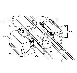
[0023] FIG. 4 is a top view of the battery assembly of Fig. 3 coupled
with frame
rails of a vehicle;
[0024] FIG. 5 is a cross-sectional view of one embodiment of the battery
assembly of FIGS. 3-4 taken at section plane 5-5 in FIG. 4;
[0025] FIGS. 6A to 7C illustrate apparatuses and processes for mounting
a
battery assembly according to an embodiment of the invention.
DETAILED DESCRIPTION
[0026] This application is directed to novel electric vehicle components
and
assemblies. The components described and claimed herein can be used in
vehicles that are
powered solely by electric motor(s) and in vehicles that are powered by a
combination of
power sources including electric motors and fossil fuels, e.g., natural gas
fuel systems.
[0027] FIG. IA illustrates a vehicle 50 with a fossil fuel system 110
disposed
within an enclosure behind a cab 104. The fuel system 110 can power a
combustion engine.
-3-

CA 03110459 2021-02-22
WO 2020/041630 PCT/US2019/047773
The vehicle 100 can be powered by an electric motor (not shown) as dsiclosed
herein. In one
embodiment, the truck has multiple distinct energy sources that are capable of
operating
independently. In certain embodiments, the truck has no combustion engine and
uses an
electric motor for its propulsion power.
[0028] FIG. 1B illustrates a side view of a vehicle 100 according to an
embodiment of the invention. The vehicle 100 has a cab 104 and a vehicle frame
for loading
cargo 108. The vehicle 100 has an electric drive system and at least one
battery to power the
electric drive system. The fossil fuel system 110 is shown in dash line,
indicating that in this
embodiment such a system is optional and may not be present.
[0029] In FIG 1B, a first battery assembly 172 is located under the cab
104 and a
second battery assembly 174 is located under the cargo frame 150. In certain
embodiments,
the truck has no battery to power its electric drive system under the cab 104,
and instead has
one or more battery assemblies under the cargo area of the vehicle. In certain
embodiments,
the truck has no battery to power its electric drive system under the cargo
frame 150 and
instead has one or more battery assemblies forward of the cargo area, e.g.,
under the cab 104.
[0030] In FIG 1B, the two batteries 172, 174 are coupled to a beam 160
that is
fixed to the cargo frame 150 and/or a frame of the cab 104. The beam 160 is a
structural
member that bears the load of the cargo frame 150 and also supports other
components
directly or indirectly, such as the wheels and axles. The beam 160 is
sometimes referred to
herein as a rail or frame rail. In certain embodiments, a battery to power the
vehicle's
electric drive system is fixed to a frame of the cab 104.
[0031] Referring to FIG. 1B, the second battery assembly 174 is sized
such that
the second battery assembly 174 does not overlap the wheels 181, 183, 185 of
the truck.
FIG. 1C shows that if the battery assembly 174 is forward of the rear wheels
183, 185, the
width dimension of a housing of the battery assembly 174 can be greater than
the distance
188 between the inside of the inner wheels. Generally, the battery assembly
174 will not be
wider than the distance 189 between the outer sides of the outermost wheels.
[0032] FIG. 1C illustrates a bottom view of the vehicle 100 according to
an
embodiment of the invention. The truck has at least one beam (or frame rail)
160 installed
under the cab 104 and the cargo frame 150. The beam 160 extends generally
along a
longitudinal direction of the vehicle 100 for holding the cargo frame 150 and
other systems
-4-

CA 03110459 2021-02-22
WO 2020/041630 PCT/US2019/047773
such as the wheels and axles, suspension, exhaust, as well as one or both of
the battery
assemblies 172, 174. Referring to FIG. 1C, the beam 160 extends to overlap a
first rear-
wheel axle 184 adjacent to or immediately neighboring the front-wheel axle
182. The beam
160 does not extend beyond the front-wheel axle 182 or beyond the first rear-
wheel axle 186
in some embodiments. In certain embodiments, the beam 160 extends to overlap
all of the
axles 182, 184, 186 or does not overlap any of the axles 182, 184, 186 when
viewed from the
bottom. FIG IC shows that the battery assemblies 172, 174 are located in a
space between
the front-wheel axle 182 and the rear-wheel axle 184 adjacent to or
immediately neighboring
the front-wheel axle 182 in one embodiment.
[00331 FIG. ID illustrates a rear view of the vehicle 100 according to
an
embodiment of the invention. The beam 160 is installed under the cargo frame
150 between
rear wheels 185. The battery assembly 174 is coupled to the beam 160 using
mounting
systems 240, 248. In certain embodiments, the clearance 194 below the rear
axles 184, 186
is greater than the height 192 of the battery assembly 174 such that the
battery assembly 174
can move under the rear axles 184, 186 and between the rear wheels 185 for
exchanging
battery assemblies. Manners of securing the first battery 172 or the second
battery 174 to the
160 are discussed below in connection with FIGS. 3-5, FIGS. 6A-6C and FIGS. 7A-
7C.
[0034] FIG. IC is a schematic view of an electric drive system according
to an
embodiment of the invention. The vehicle 100 uses at least one motor 120 for
propulsion.
At. least one battery assembly 172, 174 of the vehicle 100 provides power in
the form of
electric current to drive the motor 120. The vehicle 100 comprises an electric
current
conveyance system 122 for connecting the battery assembly 172, 174 and the
motor 120
The vehicle 100 has a transmission system (not shown) to deliver torque
generated by the
motor 120 to one or more wheel driving axles, e.g., to the axle 184.
[0035] FIG. 2 is a perspective view of the battery assembly 174
according to an
embodiment of the invention. FIG. 3 illustrates the battery assembly 174
coupled with the
beam 160. FIG. 4 is a top view of the battery assembly 174 coupled with the
beam 160.
[0036] Referring to FIG. 2, the battery assembly 174 includes a housing
200 and
at least one mounting system 240, 248 for coupling the battery assembly 174 to
the beam
160. The housing 200 comprises a first lateral portion 204, a second lateral
portion 208, and
a central portion 206 interposed between the lateral portions 204, 208 in one
embodiment.
-5-

The central portion 206 does not extend as far in the vertical direction as
the lateral portions
204, 208. A space 210 is provided between the lateral portions 204, 208 to
receive the beam
160 as illustrated in FIGS. 4 and 5. The space 210 can be disposed between an
inward facing
surface of the first lateral portion 204 and an inward facing surface of the
second lateral
portion 204. The inward facing surface can be surfaces that face toward a
central vertical
longitudinal plane of the vehicle 100 when the battery assembly 174 is mounted
thereto. In
other words, the inward surfaces can be closer to the central vertical
longitudinal plane than
are outward surfaces of the first and second lateral portions 204, 208 which
face away from
that central longitudinal plane.
100371 The housing 200 of the battery assembly 174 is generally symmetrical
about a
central plane A-A. The mounting system 240 and the mounting system 248 are
also
symmetrical about the central plane A-A. In certain embodiments, the battery
assembly 174
is asymmetrical about the plane A-A, and the mounting system 248 connected to
the first
lateral portion 204 and the mounting system 240 connected to the second
lateral portion 208
have different configurations.
100381 At least one mounting system 240 is provided in a recess 212 between
the
central portion 206 and the first lateral portion 204. The recess 212 can
include a bight
formed by the housing 200. The bight can be formed in a concave periphery on
the top side
of the housing 200. The bight can include a more complex shape such as two U-
shaped or
concave portions on opposite sides of a central vertical plane of the housing
200. The
mounting system 240 includes a first member 242 fixed to a wall of the housing
200 (e.g., to
a wall of the second lateral portion 208) that is facing the beam 160 and a
second member or
component 244 for connecting the first member 242 to the beam 160. In some
embodiments,
when the battery 174 is lifted to a position where the first member 242 of the
mounting
system 240 is at a level of the beam, the second member 244 is fixed to the
beam by fastening
a bolt (that is accessible from the space 206). In certain embodiments, the
second member
244 is fixed to the beam using at least one bolt 245, the beam 160 has at
least one through
hole 246 for receiving the bolt 245, and the second member 244 has at least
one screw hole
for receiving the bolt 245. In certain embodiments, a procedure to secure the
battery
assembly 174 to the beam comprises: (1) when the vehicle 100 is parked, moving
the battery
assembly 174 on or over the ground to place it under the beam 160; (2) lifting
the battery
assembly 174 to a set position of Fig. 3 where the through hole 246 is aligned
with a screw
hole of the bracket 244; and (3) fastening the bolt 245 to bracket 244 passing
the through hole
246. In various techniques, a motorized screwdriver, impact wrench or other
hand tool can
-6-
Date Recue/Date Received 2023-07-13

access the bolt 245 in the space 210 over the central portion 206 of the
battery assembly 174.
In another method, the second member 244 is secured to the beam 160 and the
bolt 245 may
be advanced through any of the holes in the side of the first member 242. More
specifically,
the bolt 245 can be advanced through any of the holes in a direction parallel
to the central
plane A-A and into the second member 244. An impact wrench or other tool can
be used to
secure the bolt 245 in this direction and in this manner.
[0039] FIG. 5 is a cross sectional view of the battery assembly 174 coupled
with the
frame rails 160 of a vehicle as shown in FIG. 4. The housing 200 of the
battery assembly 174
contains or encloses a plurality of battery units or cells 222. The housing
200 is fixed to the
beam (e.g., frame rail) 160 using the mounting system 240, 248 such that some
of the battery
units 222 are disposed laterally of the frame rails 160 and some are disposed
between the
frame rails 160. More particularly, the mounting system 240 enables the frame
rails 160 to
support battery cells over a wide area beneath the vehicle 100, with some
battery cells at the
central vertical longitudinal plane of the vehicle 100, and some disposed
laterally between the
central vertical longitudinal plane of the vehicle 100 and the frame rails 160
and with some of
the battery cells laterally between the frame rails 160 and the lateral outer
extent of the
vehicle 100, e.g., such that the frame rails are between at least some of the
battery cells 222
and the central vertical longitudinal plane of the vehicle 100. Referring to
the at least one
battery cell 222 are contained in portions of the housing 200 corresponding to
the mounting
system 240, e.g., in the central portion 212 of the housing, at a level of,
lateral of, and/or
below the mounting system 240 to increase the number of contained battery
cells while
allowing a vacant space 210 between the lateral portions 204, 208.
100401 FIGS. 6A to 6C illustrate processes for mounting a battery assembly
according
to an embodiment of the invention. A first bracket 260 fixed to the beam 160
is engaged with
a second bracket 250 for coupling the lateral portion 208 of the housing to
the beam. The
lateral portion 208 and the second bracket 250 can be moved from one side of
the vehicle 100
under the frame rails 160 across the central vertical longitudinal plane of
the vehicle 100 then
lifted to be disposed over at least a portion of the first bracket 260. When
the battery cell 174
is lifted from a set position of FIG. 6A to a lifted position of FIG. 6B, a
coupling pin 252 of
the second bracket 250 is elevated above a recess 262 of the first bracket
260. When
2356814.1
-7-
Date Recue/Date Received 2023-07-13

CA 031.10459 2021-02-22
the battery cell 174 is lifted from a set position of FIG. 6A to a lifted
position of FIG, 6B, a
coupling pin 252 of the second bracket 250 is elevated above a recess 262 of
the first bracket
260. When the battery assembly is in a mounted position of FIG. 6C, the
coupling pin 252 is
received in the recess 262 of the first bracket 260 such that one side of the
battery assembly
174 is coupled to one of the beams 160 of the vehicle. In certain embodiments,
subsequent
to coupling the lateral portion 208 to the beam 160 in the mounted position of
FIG. 6C,
another mounting system 248 connected to the lateral portion 204 at the other
side of the
battery assembly 174 is aligned with the beam 160 and then secured to the beam
160 using a
bolt (or other fastening system) to prevent the battery assembly 174 from
moving relative to
the beam 160 and to prevent the coupling pin 252 from coming out of the recess
262. More
details about coupling of' the brackets 250, 260 can be found in PCT
Application No,
PCT/1JS2016/039363.
[0041]
FIGs. 7A to 7C illustrate a process for mounting a battery assembly
according to an embodiment of the invention. A third bracket 280 fixed to the
beam 160 is
engaged with a fourth bracket 270 for coupling the lateral portion 208 of the
housing to the
beam 160. When the battery cell 174 is lifted from a set position of FIG. 7A
to a lifted
position of FIG. 7B, a coupling protrusion 282 of the third bracket 280 is
elevated over a hole
272 of the forth bracket 270. When the battery assembly is in a mounted
position of FIG. 7C,
the coupling protrusion 282 is inserted to the hole 272 of the fourth bracket
270 such that the
battery cell 174 is coupled to the beam 160. In some embodiments, subsequent
to coupling
the lateral portion 208 to the beam 160 in the mounted position of FIG. 7C,
another mounting
system 248 connected to the lateral portion 204 at the other side of the
battery assembly 174
is aligned with the beam 160 and then secured to the beam 160 using a bolt (or
other
fastening system) to prevent the battery assembly 174 from moving relative to
the beam 160
and to prevent the coupling pin 252 from coming out of the recess 262. More
details about
coupling of the brackets 270, 280 can be found in U.S. Application No.
14/057,410.
FURTHER DETAILS OF THE FUEL SYSTEM
-8-
Date Recue/Date Received 2021-02-22

CA 031.10459 2021-02-22
[0042] FIG. lA shows the fuel system 110 mounted to the vehicle 50
in a behind-
the-cab or back-of-cab configuration. More details of the fuel system 110 can
be found in
US Application No. 15/014,933.
[0043] While the present description sets forth specific details of
various
embodiments, it will be appreciated that the description is illustrative only
and should not be
construed in any way as limiting. Furthermore, various applications of such
embodiments
and modifications thereto, which may occur to those who are skilled in the
art, are also
encompassed by the general concepts described herein. Each and every feature
described
herein, and each and every combination of two or more of such features, is
included within
the scope of the present invention provided that the features included in such
a combination
are not mutually inconsistent.
[0044] The above presents a description of systems and methods
contemplated for
carrying out the concepts disclosed herein, and of the manner and process of
making and
using it, in such full, clear, concise, and exact terms as to enable any
person skilled in the art
to which it pertains to make and use this invention. The systems and methods
disclosed
herein, however, are susceptible to modifications and alternate constructions
from that
discussed above which are within the scope of the present disclosure.
Consequently, it is not
the intention to limit this disclosure to the particular embodiments
disclosed. On the
contrary, the intention is to cover modifications and alternate constructions
coming within
the spirit and scope of the disclosure as generally expressed by the following
claims, which
particularly point out and distinctly claim the subject matter of embodiments
disclosed
herein.
[0045] Although embodiments have been described and pictured in an
exemplary
form with a certain degree of particularity, it should be understood that the
present disclosure
has been made by way of example, and that numerous changes in the details of
construction
and combination and arrangement of parts and steps may be made without
departing from the
spirit and scope of the disclosure as set forth in the claims hereinafter.
-9-
Date Recue/Date Received 2021-02-22

Representative Drawing
A single figure which represents the drawing illustrating the invention.
Administrative Status

2024-08-01:As part of the Next Generation Patents (NGP) transition, the Canadian Patents Database (CPD) now contains a more detailed Event History, which replicates the Event Log of our new back-office solution.

Please note that "Inactive:" events refers to events no longer in use in our new back-office solution.

For a clearer understanding of the status of the application/patent presented on this page, the site Disclaimer , as well as the definitions for Patent , Event History , Maintenance Fee  and Payment History  should be consulted.

Event History

Description Date
Letter Sent 2024-06-18
Inactive: Grant downloaded 2024-06-18
Grant by Issuance 2024-06-18
Inactive: Cover page published 2024-06-17
Pre-grant 2024-05-07
Inactive: Final fee received 2024-05-07
Letter Sent 2024-04-19
Notice of Allowance is Issued 2024-04-19
Inactive: Approved for allowance (AFA) 2024-04-16
Inactive: Q2 passed 2024-04-16
Amendment Received - Response to Examiner's Requisition 2023-07-13
Amendment Received - Voluntary Amendment 2023-07-13
Examiner's Report 2023-03-13
Inactive: Report - No QC 2023-03-10
Amendment Received - Response to Examiner's Requisition 2022-10-13
Amendment Received - Voluntary Amendment 2022-10-13
Examiner's Report 2022-06-13
Inactive: Report - No QC 2022-06-07
Common Representative Appointed 2021-11-13
Letter Sent 2021-04-06
Inactive: <RFE date> RFE removed 2021-04-01
Inactive: Correspondence - Transfer 2021-03-23
Inactive: Cover page published 2021-03-19
Letter sent 2021-03-17
All Requirements for Examination Determined Compliant 2021-03-08
Request for Examination Received 2021-03-08
Request for Examination Requirements Determined Compliant 2021-03-08
Request for Priority Received 2021-03-05
Inactive: IPC assigned 2021-03-05
Application Received - PCT 2021-03-05
Inactive: First IPC assigned 2021-03-05
Letter Sent 2021-03-05
Inactive: Office letter 2021-03-05
Letter Sent 2021-03-05
Priority Claim Requirements Determined Compliant 2021-03-05
National Entry Requirements Determined Compliant 2021-02-22
Amendment Received - Voluntary Amendment 2021-02-22
Application Published (Open to Public Inspection) 2020-02-27

Abandonment History

There is no abandonment history.

Maintenance Fee

The last payment was received on 2023-07-26

Note : If the full payment has not been received on or before the date indicated, a further fee may be required which may be one of the following

  • the reinstatement fee;
  • the late payment fee; or
  • additional fee to reverse deemed expiry.

Patent fees are adjusted on the 1st of January every year. The amounts above are the current amounts if received by December 31 of the current year.
Please refer to the CIPO Patent Fees web page to see all current fee amounts.

Fee History

Fee Type Anniversary Year Due Date Paid Date
Registration of a document 2021-02-22 2021-02-22
Basic national fee - standard 2021-02-22 2021-02-22
Request for examination - standard 2024-08-22 2021-03-08
MF (application, 2nd anniv.) - standard 02 2021-08-23 2021-07-08
MF (application, 3rd anniv.) - standard 03 2022-08-22 2022-07-29
MF (application, 4th anniv.) - standard 04 2023-08-22 2023-07-26
Final fee - standard 2024-05-07
MF (patent, 5th anniv.) - standard 2024-08-22 2024-07-04
Owners on Record

Note: Records showing the ownership history in alphabetical order.

Current Owners on Record
HEXAGON PURUS NORTH AMERICA HOLDINGS INC.
Past Owners on Record
BRAD JONATHAN VAN HANEGEM
CHRIS FORSBERG
ERIC M. COUPAL-SIKES
LANDON TYERMAN
TODD F. SLOAN
Past Owners that do not appear in the "Owners on Record" listing will appear in other documentation within the application.
Documents

To view selected files, please enter reCAPTCHA code :


To view images, click a link in the Document Description column (Temporarily unavailable). To download the documents, select one or more checkboxes in the first column and then click the "Download Selected in PDF format (Zip Archive)" or the "Download Selected as Single PDF" button.

List of published and non-published patent-specific documents on the CPD .

If you have any difficulty accessing content, you can call the Client Service Centre at 1-866-997-1936 or send them an e-mail at CIPO Client Service Centre.

({010=All Documents, 020=As Filed, 030=As Open to Public Inspection, 040=At Issuance, 050=Examination, 060=Incoming Correspondence, 070=Miscellaneous, 080=Outgoing Correspondence, 090=Payment})


Document
Description 
Date
(yyyy-mm-dd) 
Number of pages   Size of Image (KB) 
Representative drawing 2024-05-21 1 22
Claims 2023-07-12 14 1,035
Description 2023-07-12 15 1,114
Claims 2022-10-12 12 807
Drawings 2021-02-21 10 475
Claims 2021-02-21 5 312
Description 2021-02-21 9 774
Abstract 2021-02-21 2 89
Representative drawing 2021-02-21 1 49
Description 2021-02-22 12 844
Claims 2021-02-22 7 417
Description 2022-10-12 14 1,082
Drawings 2022-10-12 10 540
Maintenance fee payment 2024-07-03 8 296
Electronic Grant Certificate 2024-06-17 1 2,527
Final fee 2024-05-06 5 127
Commissioner's Notice - Application Found Allowable 2024-04-18 1 578
Courtesy - Letter Acknowledging PCT National Phase Entry 2021-03-16 1 594
Courtesy - Certificate of registration (related document(s)) 2021-03-04 1 366
Courtesy - Acknowledgement of Request for Examination 2021-04-05 1 425
Courtesy - Certificate of registration (related document(s)) 2021-03-04 1 356
Amendment / response to report 2023-07-12 55 2,801
National entry request 2021-02-21 24 1,060
Voluntary amendment 2021-02-21 14 788
Patent cooperation treaty (PCT) 2021-02-21 1 87
Declaration 2021-02-21 2 43
International search report 2021-02-21 1 51
Patent cooperation treaty (PCT) 2021-02-21 1 39
Courtesy - Office Letter 2021-03-04 2 214
Request for examination 2021-03-07 4 107
Examiner requisition 2022-06-12 5 275
Amendment / response to report 2022-10-12 35 1,648
Examiner requisition 2023-03-12 3 158