Note: Descriptions are shown in the official language in which they were submitted.
SYSTEM AND METHOD FOR TARGETING THE
DISTRIBUTION OF MEDIA FROM A MOBILE PLATFORM
BACKGROUND OF THE INVENTION
1. Field of the Invention
This invention generally relates to position monitoring
networks and, more particularly, to a system and method for location-
targeting the delivery of media from a mobile platform.
2. Description of the Related Art
Humans spend more and more time in their automobiles
driving to work and to other lifestyle activities, as well as travel. In the
United States, the average American spends approximately 10 minutes
per day in an automobile. Approximately 90% of Americans own cars and
over 75% chive to work every clay. A record 107 million Americans have
automobile debt and make monthly payments. The outdoor advertising
industry aimed at targeting these drivers is estimated at $8 billion each
year.
There exist many systems that attempt to take advantage of
human user mobility to implement advertising and media distribution.
US 2013/0304565, entitled "System and Method for Advertising on Mobile
-1-
Date Recue/Date Received 2021-07-19
CA 03110715 2021-02-24
WO 2020/123028
PCT/1JS2019/056189
Platforms", and. US 2016/0267539, entitled "Individual and Fleet-Based
Vehicle-Based Wireless Marketing Device" disclose such systems. US
8,010,134, entitled "Architecture for Mobile Advertising with Location",
discloses a system that uploads particular media content to a mobile
device based upon the mobile device location. US 7,463,898, entitled
"System and Method for the Distribution of Advertising and Associated
Coupons via Mobile Media Platforms", describes a similar concept. US
8,712,630, entitled "Mobile Advertising and Compensation-Verification
System" describes a system where a display with an embedded power
source and Global Position System (GPS) receiver is adhesively attached
to a vehicle. The owner of the vehicle is rewarded for the number of miles
the vehicle is driven. The installation of the display is verified by
recording a cell phone picture. The system includes a GPS device with a
transmitter, shown communicating with a GPS satellite, that allegedly
prevents tampering or removal of the display after its installation.
However, as is well known in the art, GPS satellites only transmit data to
users ¨ they do not receive or otherwise uplinked data from users.
Similarly, although an EEPROM device is described for storing location
information and distance data, no means is presented for downloading
this data to the central entity computerized database that is tasked with
distributing rewards.
It would be advantageous if the time and location of a
portable media presentation could be tracked and recorded.
It would be advantageous if the media presentation could be
selectively enabled.
-2-
CA 03110715 2021-02-24
WO 2020/123028
PCT/1JS2019/056189
It would be advantageous if the above-mentioned media
presentation could be accurately and continuously verified. It would be
advantageous if the system included a targeting mechanism to suggest
that the media be presented in desired target locations.
It would also be advantageous if the enablement of media
presentation of the location of the media presentation could be verified
remotely, without requiring the employment of a human.
SUMMARY OF THE INVENTION
A system and method are disclosed herein that encompass
remotely deployable and activated automated signage. In one aspect, the
signage is a vehicle cover that displays advertising and is integrated, for
example, with a mobile phone software application to provide a means of
directing the signage to prime locations. Alternatively, the vehicle driver
may manually deploy the vehicle cover and the device functions in the
same manner. In one aspect, the mobile sign advertising system is
enabled as a vehicle roof mounted all-weather device that upon remote
instruction from an vehicle operator deploys and retracts a cover made of
cloth or other pliable material over and across a vehicle, either manually
or using an electric motor (battery, vehicle sourced, or solar powered).
Thus, the system creates a mobile advertising platform that seeks to
expand and capture market share within the outdoor advertising market
segment by directing the selective deployment of media to preferred target
-3-
CA 03110715 2021-02-24
WO 2020/123028 PCT/1JS2019/056189
locations, as well as (optionally) providing the automobile protection from
the elements.
The cover may display an advertising message, coupon, or
logo. The vehicle cover may be deployed automatically or manually by the
vehicle operator by removing the cover from the housing. The roof
mounted device may contain side panels displaying logos that may remain
in place on the exterior of the vehicle roof during transport and may be
affixed to the exterior of the vehicle roof by magnets or suction cups or
pads, or the roof mounted device may be removed and stored in the vehicle
following retraction of the cover by the internal motor or manually by the
vehicle operator. The roof mounted device may also contain a halo of LED
lights located under a fin that directs emitting light downward onto the
cover to illuminate the cover during darkness or low light periods. The
LED lights may be powered by a battery contained in the device housing
or an electrical system connected to the vehicle's power source. Once in a
stationary position, a receiver located in the roof mounted device can be
activated remotely by an electrical signaling device (such as Bluetooth,
cellular, or WiFi) to deploy and retract the cover through a proprietary
software application on the operator's mobile phone. Alternatively, the
system and communications are initiated by deploying the cover. The
mobile phone software application may transmit the following information
to the owner of the proprietary software: (i) a unique identifier for the
device in use (for example, radio-frequency identification) and the
operator of the vehicle assigned or in possession of the device, (ii) the
time,
date, duration and location (using mobile-satellite triangulation systems
-4-
CA 03110715 2021-02-24
WO 2020/123028
PCT/1JS2019/056189
or radio-frequency identification systems) that the device or the person
manually deployed or retracted the presentation media, and (ill) a
photographic image of the vehicle with the cover deployed. The
proprietary software may utilize graphic information system (GIS)
mapping technology to compensate the operator of the vehicle for parking
the vehicle in specified locations as identified in the mobile phone
software application.
Accordingly, a method is provided for monitoring the
provision of media distributed by a mobile platform. The method provides
a mobile platform with an attached media projection subsystem, and an
identifier (e.g., serial number) associated with the media projection
subsystem or the mobile platform. Examples of a mobile platform include
a self-powered vehicle, a towed trailer or sign, a shopping cart, a drone, or
even a backpack. The media projection subsystem is selectively enabled,
and may be a car cover, retractable screen, or a broadcasted sound to
name a few examples. In one aspect of the method, media uploads are
received from a server and projected by the media projection subsystem.
The method determines the geographic location of the mobile
platform, and verifies the identifier and the enablement of the media
projection system. Verification information, including the mobile platform
(or media projection subsystem) location, identifier, and enablement of the
media projection subsystem, is communicated to a server and stored in a
non-transitory memory.
Typically, the identifier is associated with an entity such as a
person, business, or corporation. Then, a targeting application, stored in
-5-
CA 03110715 2021-02-24
WO 2020/123028
PCT/1JS2019/056189
the server memory, enables a sequence of processor executable
instructions for directing the entity to a target location in cooperation with
analyzing the verification information. For example, the target location
may be selected from a plurality of value weighted target locations. More
explicitly, the target location may be weighted in response to geographic
location factors such as proximate vehicular traffic, line of sight,
proximate pedestrian traffic, proximity to cultural events, proximity to
cultural facilities, and combinations thereof. Otherwise, the target
location may be weighted in response to factors such as the type of media
being projected, the time of day, the day of the week, the date, the length
of time the media is being projected, and combinations thereof.
In one aspect, the identifier and media projection subsystem
include short-range wireless devices transmitting, respectively, an
identification code and an enablement signal. A personal communications
device, enabled for example as a smartphone, includes a wireless device to
receive the identification code and enablement signal, and a global
positioning system (GPS) receiver for determining the mobile platform
location. A verifier software application, stored in a non-transitory
memory, is enabled as a sequence of processor executable instructions for
verifying the identification code and the enablement of the media
projection subsystem, and providing verification information. The verifier
may be embedded with the personal communications device or the server.
Alternatively, a GPS receiver, the identifier, and a communication
subsystem are embedded with the media projection subsystem.
-6-
CA 03110715 2021-02-24
WO 2020/123028
PCT/1JS2019/056189
In another aspect, the identifier is an identification code
physically marking the media projection subsystem. Then, a personal
communications device with a camera photographs the identification code
and the deployment of the media projection subsystem. The step of
verifying the identifier and the enablement of the media projection system
includes recognizing the photographs of the identification code and media
projection subsystem deployment, respectively, as the identifier and the
enablement of the media projection subsystem.
In another aspect, the method provides a camera embedded
with media projection subsystem, and images recorded by the camera are
communicated to the server for storage in memory. The value of the
target location provided to the entity may then be modified based upon
the information provided in the images. Alternatively, the camera images
may be used to verify the enablement of the media projection subsystem.
Additional details of the above-described method, a mobile
media distribution system, a system for monitoring the occupation of a
geographic location by a mobile platform, and a system for monitoring the
provision of media distributed by a mobile platform are provided below.
BRIEF DESCRIPTION OF THE DRAWINGS
Figs. 1A and 1B are schematic block diagrams of a mobile
media distribution system.
Figs. 2A and 2B are schematic block diagrams depicting the
system of Figs. 1A and 1B as a stand-alone mobile media distribution
system.
-7-
CA 03110715 2021-02-24
WO 2020/123028
PCT/1JS2019/056189
Figs. 3A through 3C are a schematic block diagrams
depicting the system of Figs. 1A and 1B partially enabled with a personal
communications device.
Fig. 4 is a schematic block diagram depicting the system of
Figs. 1A and 1B partially enabled using photographic images.
Fig. 5 is a plan view of an exemplary target location
weighting map.
Figs. 6A through 6C are perspective views depicting the
media projection subsystem associated with an exemplary vehicle mobile
platform.
Fig. 7 is a schematic block diagram depicting a system for
monitoring the occupation of a geographic location by a mobile platform.
Fig. 8 is a schematic block diagram depicting a system for
monitoring the provision of media distributed by a mobile platform.
Fig. 9 is a flowchart illustrating a method for monitoring the
provision of media distributed by a mobile platform.
DETAILED DESCRIPTION
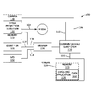
Figs. 1A and 1B are schematic block diagrams of a mobile
media distribution system. The system 100 comprises a selectively
enabled media projection subsystem 102 having an interface 104 to project
media and an interface on line 106 to supply an enablement signal in
response to the media projection subsystem being enabled. Typically, the
media projection subsystem 102 displays a media image. Alternatively, or
-8-
CA 03110715 2021-02-24
WO 2020/123028
PCT/1JS2019/056189
in addition, the media projection subsystem 102 may broadcast audio
information or sounds.
An identifier 108 is associated with the media projection
system 102, and has an interface on line 110 to supply an identification
.. code. A location device 112, here depicted as a global positioning system
(GPS) receiver, supplies the geographic location of the media projection
subsystem 102 via interface 114. The system 100 is not limited to any
particular type of location means. For example, a LORAN receiver would
be suitable to enable the system. Otherwise a LoJack0 type system might
be adapted for the purpose of location. However, at the time of this
writing, inexpensive commercial available GPS receivers are highly
accurate and easy to procure. For the sake of simplicity, the location
device is typically described as a GPS receiver in the explanations below.
A verifier 116 has interfaces connected on line 106 to receive the
enablement signal, on line 110 to receive the identification code, and on
line 114 to receive the geographic location. The verifier 116 has an
interface on line 118 to supply verification information responsive to the
enablement signal, the identification code, and the enablement signal. As
explained in more detail below, depending on the particular application,
.. the above-mentioned interface signals are communicated or downloaded
via hardlines, wirelessly, or optically. A communications subsystem 120
has an interface on line 118 to receive verification information and an
interface on line 122 to transmit the verification information to a server
124.
-9-
CA 03110715 2021-02-24
WO 2020/123028
PCT/1JS2019/056189
As used herein, a "server" may be defined as a central server,
as shown in Fig. 1A, to which a plurality of media projection systems may
report. Alternatively, as shown in Fig. 2B, the server may be a
distributed network of servers, such as might be used in a peer-to-peer
system. In general, communications may be stored and transmitted
periodically, in which the communications between the communications
subsystem 120 and the server 124 may be made via a hardline (e.g.,
Ethernet), or transmitted continuously using WiFi, cellular telephone,
Bluetooth protocols to name a few examples. The communications are not
limited to any particular type of protocol. In some aspects, the
communications include both wireless and hardline protocols, such as a
communication that begins wirelessly to a WiFi access point that
subsequently is converted to an Ethernet protocol.
The non-transitory memories described herein may be any
type or form of volatile or non-volatile storage device or medium
capable of storing data and/or other computer-readable instructions.
Examples of memories include, without limitation, Random Access
Memory (RAM), Read Only Memory (ROM), flash memory, or any
other suitable memory device. Although not required, in certain
embodiments, the systems described herein may include both a
volatile memory unit and a non-volatile storage device. The memory
may be implemented as shared memory and/or distributed memory in
a network device.
In one aspect, the identifier 108 is associated with a first
entity. The first entity may be referred to as a legal entity in some
-10-
CA 03110715 2021-02-24
WO 2020/123028
PCT/1JS2019/056189
aspects, examples of which include a human being, a business, or a
corporation. A targeting software application 126 is stored in a non-
transitory memory 128 of the server 124, enabling a sequence of processor
executable instructions for directing or suggesting to the first entity (or
media projection subsystem) a target location in cooperation with
analyzing the verification information. In one aspect, the target location
is predetermined. As such, portions of the system described herein that
are enabled with software applications may be understood to be a type of
computer system. As is well known in the art, a processor is used to
implement the steps in a software application. The memory of the
computer system typically includes some type of operating system (OS).
To reduce the clutter in the drawings, and since the interaction with an
OS, processor, and software application is so well understood, processors
and OS software are not shown in this figure.
Fig. 1B depicts the interaction between components of the
targeting application 126 and the verifier 116. In one aspect, as shown in
Fig. 2A, the targeting application 126 and verifier 116 may be collocated
in the same memory, or be combined as a single unified application.
Otherwise, the various components depicted in Fig. 1B may be non-
centrally distributed. In one aspect, the targeting application may
optionally determine a reward for the first entity, as shown in phantom,
in response to the media projection subsystem occupying the target
location. The most obvious type of reward is money. However, the first
entity may alternatively be rewarded with bitcoin, cryptocurrency,
coupons, or services. In one aspect, the target location is selected from a
-11-
CA 03110715 2021-02-24
WO 2020/123028 PCT/1JS2019/056189
plurality of weighted (in value of importance) target locations, in response
to the specific geographic location of where the media projection
subsystem is located. For example, the target location may be weighted in
response to geographic location factors such as proximate vehicular traffic,
line of sight from a particular vantage point, proximate pedestrian traffic,
proximity to cultural events, proximity to cultural facilities, and
combinations thereof. A cultural event is generally understood to be an
activity involving human beings. Likewise, a cultural facility is a facility
used by human beings, such as a museum, office building, or grocery store
parking lot. As a more explicit example, a target location may have a first
value if the media projection subsystem 102 is enabled within X feet of a
particular location, and second value, greater than the first value, if the
media projection subsystem is enabled within X/2 feet of the same
location. Other factors reflected in the weighting of the target locations
may include the type of media being projected, the time of day, the day of
the week, the date, the length of time the media is being projected, and
combinations thereof. There may be locations, such as parks, hospitals, or
freeways where signage or parking is legally restricted, and in one aspect
these locations are given a target value of zero. In one aspect, the system
may even prevent the enablement of the media projection subsystem in
legally restricted areas. The system 100 described herein is not limited to
any particular factors weighting a target location. The system is
interactive in the sense that the first entity may select a deployment
location after determining the value of a location. In this sense, the
targeting application does not so much direct the media presentation
-12-
CA 03110715 2021-02-24
WO 2020/123028
PCT/1JS2019/056189
subsystem to a particular predetermined location, as suggest multiple
possible locations.
In another aspect shown in Fig. 1A, the system 100 further
comprises an optional camera 130, shown in phantom, embedded with the
media projection subsystem 102, and having an output on line 132 to
supply images of the geographic location proximate to the media
projection subsystem. The communications subsystem 120 receives the
images from the camera and transmits them to the server. The camera
images of the environment surrounding the media projection subsystem
102 may be stored as data 132 in memory for analysis. In one aspect, the
camera images may be analyzed using an artificial intelligence (AI)
application, in conjunction with stored map images, the combination of
which operates as the location device 112. In this way, the system may
"learn" to deployment media in the optimum locations.
The camera images may also be used to modify the value of
the target location. For example, the recorded traffic in a location may be
greater than anticipated, and the target value adjusted accordingly. That
is, images recording higher pedestrian or vehicular traffic may have
greater value. The data may be used to help determine the efficacy of the
media or location. In one alternative aspect shown in phantom, the data
recorded by the camera may be imprinted with the identifier 108, stored
in a local memory 134 of the media projection subsystem, and
subsequently downloaded through the communications subsystem 120 or
through a memory peripheral, such as a thumb drive, which can be
accessed by a third party, server provider, or first entity. Alternatively or
-13-
CA 03110715 2021-02-24
WO 2020/123028 PCT/1JS2019/056189
in addition, the camera images my act to verify that the media projection
subsystem 102 has been enabled. In one aspect, simply recording a
change in images, and thus proximate traffic, can be used as a means for
proving media projection subsystem enablement.
In one aspect, the communications subsystem 120 receives
media uploads from the server 124 on line 122, and the communications
subsystem provides the media uploads to the media projection subsystem
102 on line 136.
Figs. 2A and 2B are schematic block diagrams depicting the
system of Figs. 1A and 1B as a stand-alone mobile media distribution
system. A non-transitory memory 200 is embedded with the media
projection subsystem 102. Likewise, the identifier 108, communications
subsystem 120, and GPS receiver 112 are embedded with the media
projection subsystem 102. As shown, the verifier 116 is software
application enabled as a sequence of processor executable instructions,
and stored in the memory 200, for processing the verification information.
Alternatively, as shown in phantom, the verifier 116 may be embedded in
the server memory 128. Although not explicitly depicted, communications
between the media projection subsystem and the server may be relayed
through the use personal communication devices or WiFi access points. In
this example, the identifier 108 is a code loaded into memory 200, but
alternatively it can be a mechanical device, such as a DIP switch often
associated with garage door openers. The media projection subsystem
enablement signal on line 106 may be triggered, for example, by the
deployment of a screen displaying a media message. In one aspect, the
-14-
CA 03110715 2021-02-24
WO 2020/123028
PCT/1JS2019/056189
media projection subsystem can be remotely enabled, using signals
relayed by a personal communications device or embedded
communications subsystem, from the server or from an entity (user) at a
different location. For example, the media projection subsystem may be
remotely enabled to project only in the daylight hours, and then remotely
disabled at night.
In another aspect, a GPS antenna 212 (shown in phantom)
may be embedded in the media projection mechanism, for example, if the
mechanism is a screen or cover. Since location data is only collected when
the screen is deployed, the collection of location data simultaneously
proves the enablement of the media projection subsystem 102. Otherwise,
a switch may be thrown that powers the GPS receiver when the media
projection mechanism is deployed. Again, since location data is only
collected when the media projection mechanism is deployed, the collection
of location data simultaneously acts as proof of enablement. As yet
another alternative, a powered GPS is shielded (e.g., by a metal cover)
until the media projection mechanism is activated.
The verifier application 116 is enabled with the aid of
processor 202 and OS 204. Also note that interfaces 106, 110, 114, and
118 may share the same bus line. Likewise, server 124 includes OS 206
and processor 208, with transceiver 210. For ease of understanding the
above-described functions have been described as individual components.
However, it should be understood that in practice, multiple functions may
be performed in a single device or subsystem.
-15-
CA 03110715 2021-02-24
WO 2020/123028 PCT/1JS2019/056189
Fig. 2B depicts more of a peer-to-peer type system where the
targeting application 126 is embedded in the memory of the media
projection subsystem memory 200. In this case, the targeting application
126 may use the communications subsystem 120 to communicate with at
.. least one server in the distributed network of servers 124-0 through 124-n.
In one aspect, the distributed network of servers may be other media
projections systems. As another alternative, each server in the
distributed network may include targeting and verifier applications, and
data storage block-chain mechanisms. If the system is enabled to reward
users (entities) based upon time, location, and duration of media
deployment, the rewards may also be managed using a block-chain
mechanism.
Figs. 3A through 3C are a schematic block diagrams
depicting the system of Figs. 1A and 1B partially enabled with a personal
communications device. As used herein, a personal communications
device is a device capable of wirelessly transceiving communications. A
conventional smartphone is an example of such a device. Otherwise, the
personal communications device may be a smart watch, tablet computer,
laptop computer, personal computer, or the equivalent. The personal
communications device may be capable of cellular, WiFi, and Bluetooth
communications. In addition, the personal communications device may be
a customized smartphone or proprietary device capable of nanoscale, near-
field communication (NFC), body (BAN), personal (PAN), near-me (NAN),
or wireless local area network (WLAN) to name a few examples. In
additional, the personal communications device may also be capable of
-16-
CA 03110715 2021-02-24
WO 2020/123028
PCT/1JS2019/056189
hardline (e.g., Ethernet) communications, and capable of downloading
memory-stored information into peripheral memory devices.
In this aspect, the identifier 108 includes a short-range
wireless device 300, embedded with the media projection subsystem 102,
transmitting the identification code. Likewise, the media projection
subsystem 102 includes a short-range wireless device 302 for transmitting
the enablement signal. In one aspect not shown, the identifier and media
projection subsystem may use the same transmitter. Further, the short-
range wireless device(s) may be transceivers if the system employs a
handshaking mechanism. The communications subsystem is a personal
communications device 304 that includes a wireless device 306 to receive
the identification code and enablement signal, the GPS receiver 112, an
OS 310, and processor 312. The personal communications device 304 has
a non-transitory memory 308. The verifier 116 is enabled as a sequence of
processor executable instructions, stored in the memory, for processing
the verification information. Alternatively, as shown in phantom, the
verifier may be embedded with the server 124.
Advantageously, the short range communications require
that the personal communications device 304 be in close proximity to the
media projection subsystem 102. As a result, the GPS location
measurements accurately describe the location of the media projection
subsystem 102. In some aspects, the personal communications device
wireless unit 306 is also only capable of short range communications, to
further ensure accurate GPS location measurement. Although the
communications 122 to the server 124 are depicted as wireless, they may
-17-
CA 03110715 2021-02-24
WO 2020/123028 PCT/1JS2019/056189
alternatively be enabled with hardline protocols or by downloading
personal communications device memory on a peripheral memory card.
Fig. 3B depicts some overall media performance algorithm
components. Fig. 3C depicts some aspects of an exemplary media
projection mobile application.
Fig. 4 is a schematic block diagram depicting the system of
Figs. 1A and 1B partially enabled using photographic images. In this
aspect, the identifier 108 is an identification code, as shown XXX001,
physically marking the media projection subsystem 102. Again, the
communications subsystem is a personal communications device 304. The
personal communication device 304 comprises a camera 400 to photograph
the identification code and the deployment of the media projection
subsystem. The GPS receiver 122 may be embedded with the personal
communications device, as shown. Alternatively but not shown, the GPS
receiver may be embedded with the media projection subsystem, and
communicate GPS location data to the personal communications device
via a wireless link. The verifier 116 is shown embedded in the personal
communications device memory 308, but alternatively as shown in
phantom, it may be embedded in the memory of the server. Wherever the
verifier 116 is embedded, it recognizes the photographs of the
identification code and media projection subsystem deployment,
respectively, as the identification code and enablement signal. As another
alternative, an All mapping analysis application may determine location
from the photographs.
-18-
CA 03110715 2021-02-24
WO 2020/123028
PCT/1JS2019/056189
Fig. 5 is a plan view of an exemplary target location
weighting map. Region 1 on the map may be associated with a major
highway, and deployment of the media projection subsystem in this region
rates a relatively high value. Region 2 is located in a city downtown area
and may rate an even higher value. Regions 3 and 4 may be suburban
areas, with the values associated with Region 3 being higher because of a
greater population density. Region 5 may be rural and have the smallest
value. In one aspect, the target location weighting map is stored and
maintained in the server. Components of the media projection system
(e.g., a verifier application stored in a personal communications device)
may access, and perhaps upload, the target location weighting map so as
to determine the optimum position for locating the system. Alternatively,
a separate but associated mobile map application may be used.
Figs. 6A through 6C are perspective views depicting the
media projection subsystem associated with an exemplary vehicle mobile
platform. In Figs. 6A and 6B the media projection subsystem is mounted
on the roof of a vehicle. The identifier, GPS receiver, and verifier are not
explicitly depicted. These components may be internal to the chassis
housing the media projection subsystem 102. As described above, a GPS
receiver and verifier may be embedded in other parts of the system. The
media projection subsystem 102 is mounted to a roof rack 600. In this
example, the media projection subsystem 102 may use a screen 602 to
project image data. As shown, the screen 602 may be retractable. The
screen 602 may be printed with a fixed advertising message, warning, or
alert. Alternatively, the screen may be fixed or stationary. In one aspect,
-19-
CA 03110715 2021-02-24
WO 2020/123028
PCT/1JS2019/056189
not shown, the media projection subsystem 102 further comprises a light
projecting device for illuminating the screen with the media image, or for
simply illuminating a fixed printed message at night. In another aspect,
the screen includes a field of light emitting diodes (LEDs) or liquid crystal
display (LCD) for projecting (i.e., creating) a visual image. In general, any
type of imaging system, such as a conventional projector, may be used to
create or transfer an illuminated message onto a screen or cover. As
noted above, in one aspect the light projection system is capable of
receiving updated media from the server, or capable of projecting different
types of media packages stored in memory. In one aspect, the media
presented may include a quick response (QR) code, matrix barcode, or
watermark that can be downloaded by a viewer, and used as a coupon in a
subsequent purchase, as a metric of efficacy of the media presentation.
Optionally, in combination with or as an alternative to the projection of
.. image media, the system may include a speaker 604 to broadcast an
audible sound as the media. In one aspect, the system includes a battery
606 which may be used to power retractable screens or provide power for
illuminating the screen(s).
The device housing may be constructed of a weather and
.. ultraviolet (UV) resistant molded hard plastic, synthetic material, or
metal. The device housing may be painted various colors. The leading
edge portion of the device housing that faces the front of the automobile
can be aerodynamic to reduce wind drag and noise. Located at or near the
bottom of the device housing are openings that allow the fabric car cover
to be deployed and retracted. The device housing may be an automated
-20-
CA 03110715 2021-02-24
WO 2020/123028
PCT/1JS2019/056189
roof mounted case. Alternatively, the top portion of the device may be
removed manually by the vehicle driver and deployed. As an alternative
to the rack, the housing may be attached by vibration resistant bolts,
suction cups, screws, clips, or magnetic devices that attach to the roof of
the vehicle and that are capable of keeping the device affixed to the roof
during transit or inclement weather. The perimeter of the device housing
may include a row of continuous or intermittent LED lights directly under
a small rib or fin of the housing that directs the emanating LED light in a
downward fashion over and across the fabric cover to illuminate it during
periods of darkness or low light. On the vertical portions of the device
housing facing the sides, and/or front and rear of the automobile, are
panels that can be painted or impregnated with logos or lettering. In
some aspects the housing projects a visual image (e.g., a hologram)
without the requirement of a fabric or backdrop.
Fig. GC depicts the media projection subsystem enabled as a
car cover. In this aspect, the media presentation is more likely to be a
fixed stationary message or picture. If operated in cooperation with a
personal communications device as in Fig. 4, the car cover need not
include a power source, as the personal communications device can
photograph an identifier printed on the cover while simultaneously
verifying that the cover is deployed (as shown). Alternatively, enablement
of the system can be measured with an embedded camera or
photodetector, with the use of short-range transmitters as described in
Fig. 3A, or with the use of communications subsystem.
-21-
CA 03110715 2021-02-24
WO 2020/123028
PCT/1JS2019/056189
The enablement of the media projection subsystem using a
screen can be measured in a number of different ways. In the case of a
screen, a mechanical or electrical switch, embedded camera, photodetector
detecting ambient light, laser reflecting off an extended reflective surface
of an extended screen may detect the deployment of the screen. In the
case of a more active presentation system, the enablement of an LED field
or light projection unit can act as proof of enablement. Otherwise, the
detection of a barcode, QR code, radio frequency identification (RFID), or
laser read detector can support this function.
Fig. 7 is a schematic block diagram depicting a system for
monitoring the occupation of a geographic location by a mobile platform.
The system 700 comprises a mobile platform 702 capable of occupying a
geographic location and a location device 112 (e.g., GPS receiver) having
an interface on line 114 to supply mobile platform geographic location
information. For example, the mobile platform may be a powered vehicle,
a towed trailer or cart, or a structure that occupies space and can be
carried and manipulated by hand. An identifier 108 is associated with the
mobile platform 702 and has an interface on line 110 to supply an
identification code. A verifier 116 has an interface for receiving the
geographic location information and the identifier, and an interface on
line 118 to supply verification information responsive to the geographic
location and identifier. A communications subsystem 120 has an interface
to receive verification information and an interface on line 122 to transmit
the verification information. A server 124, enabled as one of the above-
described variations, has a communications interface to accept the
-22-
CA 03110715 2021-02-24
WO 2020/123028
PCT/1JS2019/056189
verification information and a non-transitory memory 128 to store the
verification information.
The identifier 108 is associated with a first entity, and the
system may further comprise a targeting application 126. The targeting
application 126 is stored in the server memory 128, and is enabled as a
sequence of instructions for directing or suggesting a target location to the
first entity in response to analyzing the verification information. Similar
to the targeting application described above in Figs. 1-5, the targeting
application 126 calculates a target location weight responsive to a
geographic location occupied by the mobile platform. That is, a target
location weight may be response to geographic location factors such as
proximate vehicular traffic, line of sight, proximate pedestrian traffic,
proximity to cultural events, proximity to cultural facilities, and.
combinations thereof. Other weighting factors may include the time of
day, the day of the week, the date, the length of time the media is being
projected, and combinations thereof. This system may be useful, as
described above, for ensuring that certain areas are blocked and
subsequently made available for cultural events and priority vehicle
parking. As another example, the system may be used to determine that
a rental car or scooter has been returned to a proper specified location.
Although the target locations and weights may be predetermined, in some
aspects the weighting for non-predetermined areas may be calculated
concurrently with the deployment of the media projection subsystem.
That is, the target locations and the target location weights need not
necessarily be predetermined.
-23-
CA 03110715 2021-02-24
WO 2020/123028 PCT/1JS2019/056189
In one aspect, system 700 optionally comprises a selectively
enabled media projection subsystem 102 mounted to the mobile platform
702. Then, the verifier 116 additionally accepts enablement signals on
line 106 from the media projection subsystem 102 if media is deployed,
and supplies verification information on line 118 responsive to
determining the enablement of the media projection subsystem.
Similar to the system described above in Fig 3, and therefore
mentioned only briefly, the identifier and the media projection subsystem
may employ short-range wireless transmitting devices, and the
communications device is a personal communications device. Then, the
GPS receiver can be embedded with the mobile platform, media projection
subsystem if used, or the personal communications device.
Similar to the system described above in Figs. 2A and 2B, the
GPS receiver, identifier, and communication subsystems may be
.. embedded with the mobile platform, or the media projection subsystem if
used. Similar to the system described above in Fig. 4, the identifier may
be an identification code physically marking the mobile platform or media
projection subsystem if used. The communications subsystem may be a
personal communications device including a camera to photograph the
identification code and the deployment of the media projection subsystem
if present, and the verifier recognizes the photographs of the identification
code and media projection subsystem deployment of present),
respectively, as the identifier and the enablement of the media projection
subsystem.
-24-
CA 03110715 2021-02-24
WO 2020/123028 PCT/1JS2019/056189
In one aspect, the system further comprises a camera 706
having an output on line 708 to supply images of the geographic location
proximate to the mobile platform. The communications subsystem 120
receives the images from the camera and transmits them to the server 124
for storage in memory. The images may be evaluated to modify the target
location weight, to verify the occupation of a particular location, or
determine location.
Fig. 8 is a schematic block diagram depicting a system for
monitoring the provision of media distributed by a mobile platform. The
.. system 800 comprises a mobile platform 802. Like the system described
in Fig. 7, the mobile platform 802 is any portable or moveable vehicle or
structure capable of being parked and temporarily occupying a location.
In addition, mobile platform 802 includes moving vehicles, trailers or
carts under active tow, shopping carts, backpacks, and drones to name a
few examples. A selectively enabled media projection subsystem 102 is
mounted to the mobile platform 802 with an interface to supply an
enablement signal when the media projection subsystem is projecting
media. An identifier 108 is associated with a first entity and the media
projection subsystem 102, and has an interface on line 110 to supply an
identification code. A location device 112 (e.g., a GPS receiver) has an
interface on line 114 to supply media projection subsystem or mobile
platform geographic location information, which should be the same. A
verifier 116 has an interface for receiving the geographic location, the
identifier, and the enablement of the media projection system, and an
interface to supply verification information responsive to the geographic
-25-
CA 03110715 2021-02-24
WO 2020/123028
PCT/1JS2019/056189
location, identifier, and enablement of the media projection subsystem. A
communications subsystem 120 has an interface to receive verification
information and an interface on line 122 to transmit the verification
information. A server 124, enabled as one of the above-described
variations, comprises a communications interface to accept the
verification information and a non-transitory memory 128 to store the
verification information. In one aspect, the server 124 further comprises a
targeting application 126, stored the memory 128, enabled as a sequence
of processor executable instructions for directing or suggesting target
locations to the first entity in cooperation with analyzing the verification
information.
In one aspect, the targeting application 126 supplies or
calculates a plurality of weighted target location responsive to a
corresponding plurality of geographic locations through which the mobile
platform traverses. In other words, the value of the target locations may
change constantly as the mobile platform continually moves through
different locations. Other details of the system of Fig. 8 are essentially
identical to the features and variations presented in the descriptions of
Figs. 1-4 above, and are not repeated here in the interest of brevity.
The systems described above can be adapted for use in a
model where an advertiser pays for service based upon performance. For
example, an advertising client may contract with a system provider
stipulating a target market and deployment hours/rate. The system
provider determines geo-fenced locations that meet or exceed the
.. advertiser's target market based on location, demographics, traffic,
-26-
CA 03110715 2021-02-24
WO 2020/123028
PCT/1JS2019/056189
population density, and other variables. In one variation, system enablers
(e.g., entities or drivers) use a mobile application in conjunction with the
media projection subsystem that is deployed in geo-fenced region for a
period of time. Platform deployment time, location, quality code, and user
information are recorded by the server. A system provider algorithm
determines platform performance based on length of deployment,
contracted rate, parking cost reimbursement, and location quality code.
As noted above, in one aspect a personal communications
device mobile application communicates with the media projection system
using a near-field, low power (e.g., Bluetooth) protocol. This mobile
application may require user authentication and handshaking with media
projection system as a means of identification and verification. The
mobile application may provide the user with geo-fenced target
deployment assignments, user account info, module status, and module
controls. Driver deployment is logged when the driver pairs and connects
the application with the media projection subsystem, and in one aspect,
the driver deploys the media advertisement by pulling down a vinyl roller.
Location and deployment time metrics are recorded using mobile
GPS/cell-tower telemetric capabilities and time features. The user data
and metrics may be transmitted using cellular wireless electronic
communication to the server.
As at least partially seen in Figs. 6A and 6B, the media
projection system may include a roof mounted rack, battery compartment,
pulldown vinyl advertisement, microcontrollers, and microchip wireless
antenna. The projection system is mounted to a vehicle and the driver
-27-
CA 03110715 2021-02-24
WO 2020/123028
PCT/1JS2019/056189
may then be directed to preferred deployment locations using the mobile
map application. That is, a mobile map application may display geo-
fenced locations corresponding to areas where the driver is eligible to
make money by deploying advertising media. The driver syncs their
mobile device application to the media projection system to control and
confirm the device location, deployment, and length of deployment.
The systems described above support a targeted mobile sign
system, where the mobile sign is selectively deployed. As explained above,
the sign may be a car cover with an advertising logo or message. In
cooperation with the deployment of the sign, an organization or user
associated with the sign is directed to preferred locations. For example,
the deployment of the sign along a busy urban thoroughfare is likely to
have a greater value than deployment on a suburban side-street. Other
factors that may be used to calculate target value may include the time of
day and the length of deployment. Thus, some key features to the system
are determining that the sign has actually been deployed, and once
deployed, the location of the sign. In some aspects, the sign is a type of
visual display, but other aspects may include just an auditory
presentation, a combination visual and auditory presentation, or a
presentation that is able to interact with a proximate viewer.
In one aspect, the sign communicates a deployment message
and supporting systems receive the deployment message and determine
the deployment location. This information can be relayed in real-time to a
server entity. Alternatively, the information can stored in memory of the
.. supporting system and transferred to the server at periodic intervals or
-28-
CA 03110715 2021-02-24
WO 2020/123028
PCT/1JS2019/056189
upon the attainment of predetermined metrics such as the number of
deployments. In this aspect, the sign can be enabled with a relatively
simple transmitting device or memory.
The supporting system may be a smartphone with a
proprietary application for interrogating or receiving interrogations from
the sign. For example, the system may assume that smartphone is both
enabled with a GPS application, and in the same approximate location as
the deployed sign, if the sign uses a short range communication system
such as Bluetooth, NFC, or WiFi. Likewise, the supporting system may be
a local or mobile WiFi hotspot, in which case the deployment signal is
relayed to the server, and it may be possible for the server to determine
the location of the WiFi hotspot, for example, by communicating with
devices adjacent to the hotspot that are enabled with GPS receivers.
In another aspect, the sign includes mechanisms for
determining both deployment and location. As above, this information
can be communicated to a supporting system in real-time using a wireless
communications system. Again this information can be communicated to
a smartphone with a proprietary application via Bluetooth, WiFi, or even
cellular communications. Alternatively, the communications can be
related via a WiFi hotspot, or sent more directly to the server via cellular
communications. Alternatively, the deployment and location information
can be stored and transferred occasionally or periodically using a wireless
communications system, using a hard-wired link, or memory peripheral.
In one aspect, the media projection subsystem can be equipped with
-29-
CA 03110715 2021-02-24
WO 2020/123028
PCT/1JS2019/056189
inertial measurement unit (IMO, such as an accelerometer or gyroscope,
to detect changes in location.
Fig. 9 is a flowchart illustrating a method for monitoring the
provision of media distributed by a mobile platform. Although the method
is depicted as a sequence of numbered steps for clarity, the numbering
does not necessarily dictate the order of the steps. It should be
understood that some of these steps may be skipped, performed in
parallel, or performed without the requirement of maintaining a strict
order of sequence. The method steps are supported by the above system
descriptions and, generally, the method follows the numeric order of the
depicted steps. The method starts at Step 900.
Step 902 provides a mobile platform with an attached media
projection subsystem, and an identifier associated the media projection
subsystem. Exemplary media projection subsystem may comprise a car
cover, fixed screen, or retractable screen for displaying a media image.
The media projection subsystem may also employ a light projection device,
a field of LEDs, and an audio speaker. Step 904 selectively enables the
media projection subsystem. Step 906 determines the geographic location
of the mobile platform. Step 908 verifies the identifier and the
enablement of the media projection system. Step 910 communicates, to a
server, verification information including the mobile platform location,
identifier, and enablement of the media projection subsystem. As noted
above, there is no necessity that these steps be performed in the
particular order listed above. In Step 912 the server accepts the
-30-
CA 03110715 2021-02-24
WO 2020/123028
PCT/1JS2019/056189
verification information, and in Step 914 the server stores the verification
information in a non-transitory memory.
In one aspect, the identifier of Step 902 is associated with a
first entity, and Step 916 directs or suggests a target location to the first
entity in cooperation with analyzing the verification information using a
targeting software application, stored in the server memory, and enabled
as a sequence of processor executable instructions. A target location
weight may be responsive to the type of geographic location occupied by
the mobile platform. Some geographic location factors are proximate
vehicular traffic, line of sight, proximate pedestrian traffic, proximity to
cultural events, proximity to cultural facilities, and combinations thereof.
A target location weight may also be responsive to factors such as the type
of media being projected, the time of day, the day of the week, the date,
the length of time the media is being projected, and combinations thereof.
.. As shown with the arrow leading back to Step 906, the selection of
location may be influenced by the value of the location.
In one aspect, Step 902 provides an identifier comprising a
short-range wireless device transmitting an identification code, and with
the media projection subsystem comprising a short-range wireless device
for transmitting an enablement signal. In addition, Step 902 may further
provide a personal communications device comprising a short-range
wireless device to receive the identification code and enablement signal,
and a GPS receiver for determining the mobile platform location. Then,
verifying the identifier and the enablement of the media projection system
.. in Step 908 includes using a verifier software application, stored in a non-
-31-
CA 03110715 2021-02-24
WO 2020/123028
PCT/1JS2019/056189
transitory memory, enabled as a sequence of processor executable
instructions for verifying the identification code and the enablement of the
media projection subsystem. The verifier software application may be
embedded with either the personal communications device or the server.
Alternatively, Step 902 embeds a GPS receiver, the
identifier, and a communication subsystem with the media projection
subsystem. In this case, the verifier software application is stored in a
non-transitory memory of the media projection subsystem. The
verification information communicated in Step 910 is communicated using
the embedded communications subsystem. This method permits constant
verification updates if so desired.
In another aspect, Step 902 provides the identifier as an
identification code physically marking the media projection subsystem,
and also provides a personal communications device including a camera to
photograph the identification code and the deployment of the media
projection subsystem. Then, verifying the identifier and the enablement
of the media projection system in Step 908 includes recognizing the
photographs of the identification code and media projection subsystem
deployment, respectively, as the identifier and the enablement of the
media projection subsystem.
In one aspect, Step 903a receives media uploads from the
server, and enabling the media projection subsystem in Step 904 includes
the media projection subsystem projecting the media uploads. Optionally,
Step 903b uplinks a target location weighting map, which may influence
the deployment location of Step 904. In another aspect, Step 902 provides
-32-
CA 03110715 2021-02-24
WO 2020/123028
PCT/1JS2019/056189
a camera embedded with the media projection subsystem, and Step 918
communicates images recorded by the camera to the server for storage in
memory. In another variation, the camera may be used in verifying
system enablement in Step 908.
System and methods have been provided for monitoring the
deployment of media and the occupation of geographic locations.
Examples of particular message structures, schematic block linkages, and
hardware units have been presented to illustrate the invention. However,
the invention is not limited to merely these examples. Other variations
and embodiments of the invention will occur to those skilled in the art.
WE CLAIM:
-33-