Note: Descriptions are shown in the official language in which they were submitted.
Agent Docket No. P10408CA00
ELECTRICAL POWER UNIT
CROSS REFERENCE TO RELATED APPLICATION
[0001] The present application claims the benefit of U.S. provisional
application Ser. No.
62/986,247, filed Mar. 6, 2020, which is hereby incorporated herein by
reference in its entirety.
FIELD OF THE INVENTION
[0002] The present invention relates to electrical power and/or data outlet or
receptacle systems
for use in work areas or the like.
BACKGROUND OF THE INVENTION
[0003] Electrical devices for home or business use typically derive power
supplied from an
electrical socket or outlet. Generally, the electrical outlet includes a pair
of openings to receive a
corresponding pair of prongs of an electrical plug, and often an additional
opening to receive a
grounding prong of the electrical plug. A typical electrical socket is
primarily designed for use
with electrical devices that use alternating current (AC) to operate. However,
many portable
personal electrical devices today utilize low voltage direct current (DC)
power to charge and/or
operate. These portable electrical devices often use a universal serial bus
(USB) based
connection to receive power for charging via a 1JSB interface in the device,
and may also
transfer data through the USB interface. Thus, for these portable electrical
devices to charge and
operate in conjunction with a typical electrical outlet, some form of a power
adapter is needed to
provide DC power from the AC electrical outlet. A portable power adapter
required to provide
low voltage DC power from the AC electrical outlet, however, is somewhat bulky
and
inconvenient for a user of a portable electrical device to carry in ease the
portable electrical
device requires additional charge.
SUMMARY OF THE INVENTION
[0004] The present invention provides an electrical power unit that allows
powering of AC-
powered devices and DC-powered electrical devices without the use of bulky
portable power
adapters and in a manner similar to a conventional electrical outlet. More
specifically, the present
invention is directed to a surface-mountable electrical power unit with
exposed portions having a
low thickness profile and configured to provide low voltage DC (such as USB)
and AC power
- 1 -
Date Recue/Date Received 2021-03-05
Agent Docket No. P10408CA00
sourcing receptacles for charging respective DC-powered and AC-powered
electrical devices
without the use of portable power adapters.
In one form of the present invention, an electrical power unit or electronic
data unit
includes an outer housing, a circuit board positioned inside the outer
housing, a frame inserted
inside the outer housing, and a face plate fitted over the outer housing. The
circuit board supports
a high voltage AC electrical receptacle, a low voltage DC electrical
receptacle, and optionally a
switch, each of which is electrically connected to the circuit board. The
frame defines a plurality
of outlet openings for receiving respective one of the AC electrical
receptacle, the DC electrical
receptacle, and the switch. The face plate defines outer receptacle openings
that align with
respective outlet openings of the frame to provide access to the respective AC
electrical
receptacle, DC electrical receptacle, and switch.
[0005] Thus, the present invention provides an electrical power unit or
electronic data unit that
may be installed in a surface, such as a wall or a desk, and that allows DC-
powered devices and
AC-powered devices to easily connect to the same power source without use of
bulky external
power adapters. The electrical power unit of the present invention is easy to
assemble, easy to
use, and easy to install. Moreover, the unit of the present invention is
compactly designed to
have a very low thickness profile so that, when installed, it occupies minimal
amount of space in
the surface.
[0006] These and other objects, advantages, purposes and features of the
present invention will
become apparent upon review of the following specification in conjunction with
the drawings.
BRIEF DESCRIPTION OF TIIE DRAWINGS
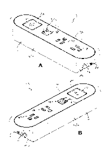
[0007] FIGS. IA and 1B are top perspective views of an electrical power unit
in accordance with
the present invention.
[0008] FIG. 2A is a side cross-sectional view of the electrical power unit
illustrated in FIGS. IA
and I B, shown mounted at an opening in a surface;
[00091 FIG. 2B is another side cross-sectional view of the electrical power
unit illustrated in
FIGS. I A and 1B, shown with internal electrical components omitted;
[0010] FIGS. 3A and 3B are exploded top perspective views of the electrical
power unit
illustrated in FIGS. lA and 1B;
- 2 -
Date Recue/Date Received 2021-03-05
Agent Docket No. P10408CA00
[0011] FIGS. 4A and 4B are top perspective views of another electrical power
unit in accordance
with the present invention;
[0012] FIGS. 5A and 5B are exploded top perspective views of the electrical
power unit
illustrated in FIGS. 4A and 4B; and
[0013] FIG. 6 is a perspective view of the electrical power unit of FIGS, 4A
and 413 shown
electrically coupled to the electrical power unit of FIGS. lA and 113, and
with an electrical power
cord for supplying power to both electrical power units.
DETAILED DESCRIPTION OF PREFERRED EMBODIMENTS
[0014] Referring now to the drawings and the illustrative embodiments depicted
therein, a wall
or surface mountable electrical power unit or electronic data unit 10 includes
a circuit board 12
encased in an outer housing 14, a frame 16, and a face plate IS, such as shown
in FIGS. 1A-3B.
The circuit board 12 supports at least one alternating current (AC) electrical
receptacle 20 and at
least one low voltage direct current (DC) receptacle 22, and a switch 24, all
in electrical
communication with the circuit board 12. The circuit board 12 may be a printed
circuit board
(PCB) having a plurality of electrical conductors formed or established along
the board 12 to
route power to the plurality of high voltage AC electrical receptacle 20, DC
receptacle 22, and
the switch 24. In the illustrated embodiment, DC receptacle includes a pair of
universal serial
bus (USB) receptacles 22a, and an additional high voltage AC electrical
receptacle 21 is spaced
from the circuit board. The AC electrical receptacles 20, 21, the DC
receptacle 22, and the
switch 24 are arranged in-line as shown in FIGS. 3A and 3B. Other arrangements
are also
envisioned.
[0015] In FIGS. 3A and 3B, switch 24 is represented by a pushbutton cover with
four corner
guides 24a and a pair of latch tabs 24b that limit the outward or forward
movement of the switch
cover in response to an internal spring. A rear portion of switch 24 is
supported by a pair of
rearward-extending walls 24c as shown in FIG. 28. Optionally, the front
surface of switch 24
may be translucent and the switch internally illuminated so that the switch
can be readily
identified in dark environments. Switch 24 is an optional component of the
electrical power unit
10, and various combinations of AC receptacles 20, 21 and/or DC receptacles 22
and/or
electrical data connections (not shown) may be installed, without departing
from the spirit and
scope of the present invention.
- 3 -
Date Recue/Date Received 2021-03-05
Agent Docket No. P10408CA00
[0016] In the illustrated embodiment, each AC electrical receptacle 20
includes female line
receptacle opening 26a, a female neutral receptacle opening 26b, and a female
ground opening
28 that accept respective prongs of inserted plugs and deliver current to AC-
powered devices.
Although the illustrative embodiment shown in FIGS. 1A-33 depicts two AC
electrical
receptacles 20, 21 electrically connected to the circuit board 12, it should
be understood that any
desired number of AC electrical receptacles 20, 21 may be provided.
[0017] Each DC receptacle 22 provides low voltage direct current (DC) to an
electrical device
connected, such as via a USB interface of the electrical device, to the
electrical power unit 10. In
the illustrated embodiment, the DC receptacle 22 provides a USB 2.0 Standard-A
type
connectors 22a, but it will be appreciated that the DC receptacle 22 may take
other forms. For
example, a USB 2.0 Standard-B type connector, Mini-A Mini-B, Micro-A, Micro-B,
coaxial, or
any other low voltage DC connector. It is further contemplated that the USB
receptacles 22a do
not include a host device and/or active data pins, so that any capable USB
device can be charged
and/or operated using a standard USB cable. It should also be understood that
one or a plurality
of DC receptacles 22 may be supported by the circuit board 12, and the USB
receptacles 22a
may provide power without providing data to connected USB devices, or both
power and data. In
the illustrated embodiment, two USB receptacles 22a are provided in an
adjacent and parallel
arrangement to one another, although other arrangements are also envisioned.
[0018] Power received from an input power cable 30 (FIG. 6) from a mains power
source (not
shown) is directed into the outer housing 14 via an opening 32 that is fitted
with a dual-opening
strain relief 34 as shown in FIGS. 1A, 18, 3A, and 3B. If one of the openings
in the strain relief
34 is not being utilized, it may be fitted with a plug to seal contaminants
out of the housing 14.
The strain relief 34 is a two-piece unit that is clamped around the power
cable 30 by a pair of
screws 36 (FIGS. 3A and 3B). Power cable 30 supplies high voltage AC
electrical power to the
AC electrical receptacles 20, 21, either directly or via the switch 24.
Additionally, the AC power
is directed to a regulated power supply (RPS) 38 and rectifier 40, forming a
circuit for
transforming AC power to low voltage regulated DC power. The converted current
is then
provided to the low voltage receptacle 22. Switch 24 may be operable to shut
off electrical
continuity from the input power cable 30 to the entire circuit board 12, or
alternatively to AC
electrical receptacles 20, 21, or DC receptacle 22 individually, or to another
electrical power unit
110 as will be described below. Optionally, a plurality of switches 24 may be
provided to
- 4 -
Date Recue/Date Received 2021-03-05
Agent Docket No. P 10408CA00
selectively disconnect one or more AC electrical receptacles 20, 21 and/or DC
receptacle 22
from the that, in the illustrated embodiment, includes a pair of universal
serial bus (USB)
receptacles 22a., and a switch 24. It is further envisioned that one or more
switches 24 may
additionally or alternatively regulate power supply to other electrical
devices electrically
connected to the main electrical power supply circuit (not shown), such as a
lamp, air supply, or
the like.
[0019] As best seen in FIGS. 3A and 3B, the outer housing 14 is configured as
a generally
rectangular and hollow box having longitudinally extending side walls 42a, 42b
and laterally
extending end walls 44a, 44b, with generally planar rear or bottom wall 46.
Opposite the rear
wall 46 is an opening 48 for receiving the circuit board 12, such that the
circuit board 12 is fitted
inside and is substantially encased in the outer housing 14, with forward or
face portions of the
AC electrical receptacles 20, 21, DC receptacle 22, and switch 24 being
approximately aligned
with forward edges of the walls 42a, 42b, 44a, 44b, such as shown in FIG. 2B.
Referring to
FIGS. 3A and 313, end walls 44a, 44b each have an outwardly-extending flange
50 defining an
opening 52 for receiving a respective threaded fastener 54 that can be secured
into a substrate 56,
such as shown in FIGS. 2A and 211 In addition, each side wall 42a, 42b has a
pair of inwardly-
directed tabs 58 for receiving respective fasteners 59, such as threaded
screws, rivets, or
compressible tubular pins, which secure the frame 16 to the outer housing 14
at the tabs 58. A
series of spaced-apart openings 62 formed along the upper or forward edge
regions of each side
wall 42a, 42b receive respective resilient tabs 62 (FIG. 2A) along an interior
side region of the
face plate 18, so that the face plate 18 can be removably secured to the
housing 14 after the outer
housing 14 has been secured to the substrate 56 with fasteners 54.
[0020] The frame 16 is provided to secure and/or limit movement of the
receptacles 20, 21, 22
and circuit board 12 inside the outer housing 14. In the illustrated
embodiment, and as best
shown in FIGS. 3A and 313, the frame 16 defines a plurality of apertures or
outlet openings 64,
65, 66, and 68 of corresponding shapes and sizes to receive the respective AC
electrical
receptacles 20, 21, DC receptacle 22, and switch 24. The apertures 64, 65, 66,
and 68 can be
shaped and sized to allow corresponding receptacles and switches to be mounted
in different
arrangements and orientations, as desired. It should further be appreciated
that if switch 24 is not
included on the circuit board 12, switch aperture 68 may be omitted or used
for another purpose,
such as an additional outlet receptacle or wire pass-through, for example.
- 5 -
Date Recue/Date Received 2021-03-05
Agent Docket No. P10408CA00
[0021] The frame 16 is formed as a generally rectangular plate with downwardly-
bent side
portions 70 fitting down alongside inside surfaces of the outer housing's side
walls 42a, 42b
(FIGS. 3A and 313). A Z-shaped end portion 72 includes an outboard vertical
leg 72a, an
inwardly-directed horizontal leg 72b, and an inboard vertical leg 72c. The
outboard vertical leg
72a fits down alongside the outer housing's end wall 44b, while the horizontal
leg 72h holds the
strain relief 34 in position at opening 32 formed in end wall 44h, and the
inboard vertical leg 72c
helps to stabilize the AC electrical outlet 21. Fastener openings 74 receive
the fasteners 59,
which then pass into respective openings in the inwardly-directed tabs 58 of
the outer housing
14. Frame 16 and outer housing 14 may be formed from stamped sheet metal,
although it is
envisioned that molded resinous plastic may also be used.
[0022] In the illustrated embodiment, a flexible pre-formed insulator sheet 76
forms an
electrically insulative tray beneath and alongside the circuit board 12.
Insulator sheet 76
includes a folded-over tab region 76a that receives a fastener 78, which is
secured to the circuit
board 12 as shown in FIG. 3B. Fastener 78 has a lower end portion that engages
bottom wall 46
of outer housing 14, such as at a screw boss (not shown) to support the
circuit board 12 at the
bottom wall 46. A separate grounding screw 80 passes through the bottom wall
46 and
electrically connects to a ground conductor of the input power cable 30 so
that outer housing 14
is electrically grounded.
[0023] Prior to insertion of the circuit board 12, receptacles 20, 21, 22, and
switch 24 into the
outer housing's opening 48, the frame 16, circuit board 12, and receptacles
20, 21, 22 may be
combined to form a pre-assembly that can be handled as a unit, optionally with
power cord 30
and strain relief 34 fitted as well.. To form the pre-assembly, rear portions
of the switch 24, AC
electrical receptacles 20, 21, and DC receptacle 22 are first inserted through
the respective outlet
openings 64, 65, 66, 68 of the frame 16, with the face portions of the
respective AC electrical
receptacles 20, 21, DC receptacle 22, as switch 24 positioned along a forward
surface 82 of the
frame 16. Once so-inserted, the switch 24, AC electrical receptacles 20, 21,
and DC receptacle
22 are retained at the frame 16 such as by spring-clips 84, and are then wired
to the circuit board
12, such as in one or more different manners disclosed in commonly-owned and
co-pending U.S.
patent application, Ser. No. 16/403,922, Pub. No. 2019/0341712, filed May
6,2019, and
commonly-owned and co-pending U.S. provisional application, Ser. No.
16/917,076, Pub. No.
2021-0005989, filed Jun. 30, 2020, both of which are hereby incorporated
herein by reference in
- 6 -
Date Recue/Date Received 2021-03-05
Agent Docket No. P 10408CA00
their entireties. This allows the frame 16 to be grasped and used as a fixture
for the circuit board
12, receptacles 20, 21, 22, and switch 24 while establishing electrical
connections to the circuit
board 12. In this way, fixing the position of frame 16 relative to outer
housing 14 also fixes the
positions of the circuit board 12, receptacles 20, 22, and switch 24 relative
to the outer housing
14.
[0024] As can be best seen in FIGS. 1 and 2, the face plate 18 snugly fits
over the outer housing
14, and may attach to the outer housing 14 with resilient latch-tabs 62,
adhesive, or the like. The
face plate 18 defines a plurality of outer receptacle openings 86, 87, 88, 90
that align with
respective AC receptacles 20, 21, DC receptacles 22a, and switch 24 to provide
access to those
components. Switch 24 is configured as a push-on push-off switch that toggles
between open-
connection and closed-connection states. It should also be appreciated that if
switch 24 is not
included on the circuit board 12, outer receptacle opening 90 may be omitted
or used for another
purpose, such as an additional outlet receptacle or wire pass-through, for
example. It is further
contemplated that an adhesive-backed decorative finish inlay or overlay (not
shown) may be
attached to an outer surface of the face plate 18 in order to provide a
desired aesthetic
appearance.
[0025] Referring now to FIGS. 4A-5B, another electrical power unit 110 is of
substantially the
same as the first power unit 10 described above, which has substantially the
same construction
but without a power switch. Like components and features of the switchless
unit 110 are
identified with like reference numbers by the addition of 100 so that the
components and features
may be understood with reference to the above discussion of the electrical
power unit 10, and the
remaining description focuses on the minor distinctions as well as the ability
to link the
switchless electrical power unit 110 to the switched unit 10 as shown in FIG.
6.
[0026] As described above, the switch 24 on electrical power unit 10 may be
used to selectively
energize and de-energize the switchless electrical power unit 110 so that
electrical devices
receiving power from the switchless electrical power unit 110 can be powered
and de-powered
by depressing the switch 24 on electrical power unit 10. A jumper cord 130
carries high voltage
AC electrical power from switch 24 to the switchless electrical power unit 110
when the switch
24 is closed. The strain relief 134 of the switchless unit 110 receives the
jumper cord 130
through one opening, while the adjacent opening is fitted with a plug 192
(FIG. 6). It will be
appreciated that if a switchless unit 110 and jumper cord 130 are not provided
with the electrical
- 7 -
Date Recue/Date Received 2021-03-05
Agent Docket No. P10408CA00
power unit 10, a plug may be fitted into one of the openings of the strain
relief 34 on the power
unit 10. Optionally, additional switched or switchless power units may be
added downstream of
the switchless unit 110 as desired. This allows for additional access to
electrical power, such as
in work spaces, with remote control of the downstream units via the switch on
the first unit 10 to
which power cord 30 is directly connected, similar to the manner described in
commonly-owned
U.S. patent application, Pub. No. 2020/0388971, filed June 8,2020, which is
hereby
incorporated herein by reference in its entirety.
[0027] Therefore, the electrical power unit of the present invention provides
for convenient
access to electrical power and/or electronic data. The power or data units are
mountable in a
surface, such as a wall, desk, or the like, and allow DC-powered devices and
AC-powered
devices to easily connect to the same power source without use of bulky
external power adapters.
Further, the electrical power unit of the present invention is configured as a
compact, low
thickness profile unit that is easy to assemble, easy to install, and easy to
use. The system may
also be particularly well suited for use in the hospitality industry, such as
with one power unit
mounted in a headboard of a bed, and another power unit mounted at a desk or
nightstand and its
power controlled via a switch on the headboard unit.
[0028] Changes and modifications in the specifically described embodiments may
be carried out
without departing from the principles of the present invention, which is
intended to be limited
only by the scope of the appended claims, as interpreted according to the
principles of patent law
including the doctrine of equivalents.
- 8 -
Date Recue/Date Received 2021-03-05