Note: Descriptions are shown in the official language in which they were submitted.
ZONE HEATING FOR RESPIRATORY CIRCUITS
[0001] DELETED
100021 DELETED
BACKGROUND
Field
[0003] The present disclosure generally relates to humidification
systems for
providing humidified gases to users, and more particularly to heating gases in
respiratory
circuits used with humidification systems.
Description of Related Art
[0004] Many gas humidification systems deliver heated and humidified
gases for
various medical procedures, including respiratory treatment, laparoscopy, and
the like.
These systems can be configured to control temperature, humidity and flow
rates using
feedback from sensors. To maintain desirable properties upon delivery to a
user, a breathing
circuit can have heaters associated with gas conduits where the heaters
provide heat to the
gas as it flows to and/or from the user. The conduit heaters can be controlled
to provide heat
to the gas so that the gas arrives to the user having desirable properties
such as temperature
and/or humidity. A humidification system can include a temperature sensor to
provide
feedback to a humidification controller which can adjust and/or modify power
delivered to
the conduit heaters to achieve a target temperature at a location along an
associated conduit.
-1-
Date Recue/Date Received 2021-03-10
SUMMARY
[0005] The systems, methods and devices described herein have
innovative
aspects, no single one of which is indispensable or solely responsible for
their desirable
attributes. Without limiting the scope of the claims, some of the advantageous
features will
now be summarized.
[0006] Some embodiments provide for an inspiratory limb for a
breathing circuit.
The inspiratory limb described herein is particularly useful in situations
where heated and
humidified gasses must pass through two distinct environments. This can be a
problem, for
example, in infant incubators where the temperature is significantly higher
than the
surrounding environment or where a portion of the conduit delivering the
gasses to the
patient is under a blanket. The embodiments disclosed herein, however, can be
used in any
environment where heated and/or humidified gas is delivered to a patient and
are not limited
to uses where the inspiratory limb passes through two distinct environments.
[0007] The inspiratory limb can include a first segment of the
inspiratory limb
that comprises a first structure forming a conduit, the conduit configured to
transport a
humidified gas, and wherein the first segment of the inspiratory limb includes
a first heater
wire circuit. The inspiratory limb can include a second segment of the
inspiratory limb that
comprises a second structure forming a conduit configured to transport the
humidified gas,
wherein the second structure is configured to mechanically couple to the first
structure of the
first segment to form an extended conduit for the humidified gas and wherein
the second
segment of the inspiratory limb includes a second heater wire circuit. The
inspiratory limb
can include an intermediate connector that includes a connection circuit that
electrically
couples the first heater wire circuit to the second heater wire circuit,
wherein the intermediate
connector can be coupled to a patient-end of the first segment of the
inspiratory limb and a
chamber-end of the second segment of the inspiratory limb to form a single
conduit for the
humidified gases. The intermediate connector can be covered by a portion of
the first
segment of the inspiratory limb, a portion of the second segment of the
inspiratory limb, or a
portion of both the first and second segments of the inspiratory limb such
that the
intermediate connector is internal to the inspiratory limb.
-2-
Date Recue/Date Received 2021-03-10
100081
The inspiratory limb can be configured to operate in two heating modes.
In a first heating mode, electrical power passes through the intermediate
connector to provide
power to the first heater wire circuit without providing power to the second
heater wire
circuit. In a second heating mode, electrical power passes through the
intermediate
connector to provide power to both the first heater wire circuit and the
second heater wire
circuit. For example, the intermediate connector can include electrical
components
configured to direct electrical power along different paths based at least in
part on a direction
of current flow and/or a polarity of voltage. The intermediate connector can
include
conductive tracks which can provide a short (e.g., a direct electrical
connection with no
intervening electrical components) between one or more wires in the first
heater wire circuit
and one or more wires in the second heater wire circuit. The intermediate
connector can
include conductive tracks which electrically couple one or more wires in the
first heater wire
circuit to one or more wires in the second heater wire circuit, where the
conductive tracks
include electrical components such as, for example and without limitation,
diodes,
transistors, capacitors, resistors, logic gates, integrated circuits, or the
like. In certain
embodiments, the intermediate connector includes a diode electrically coupled
to both the
first heater wire circuit and the second heater wire circuit. In certain
embodiments, the
inspiratory limb can further comprise a first sensor circuit having a first
sensor positioned at
the intermediate connector. In certain embodiments, the inspiratory limb
further comprises a
second sensor circuit having a second sensor positioned at a patient-end
connector, the
patient-end connector being positioned at a patient-end of the second segment
of the
inspiratory limb. The inspiratory limb can be configured to operate in two
sensing modes. In
a first sensing mode, signals from the first sensor are received without
receiving signals from
the second sensor. In a second sensing mode, signals from the second sensor
are received
without receiving signals from the first sensor. In some embodiments, sensing
includes
receiving signals from both the first and second sensors in parallel. In such
embodiments, an
algorithm can determine a parameter measured by the first sensor based at
least in part on the
signals received in parallel from both the first and second sensors. In
certain embodiments,
the intermediate connector includes a diode electrically coupled to both the
first sensor
circuit and the second sensor circuit. The patient-end connector can be
configured to provide
electrical connections for the second sensor circuit. Similarly, the patient-
end connector can
-3-
Date Recue/Date Received 2021-03-10
be configured to provide electrical connections for the second heater wire
circuit. The
sensors can be temperature sensors, humidity sensors, flow sensors, or the
like. The first and
second sensors can be sensors configured to measure one or more parameters,
such as
temperature, humidity, flow rate, oxygen percentage, or the like. In some
embodiments, the
first and second sensors are configured to measure at least one like parameter
(e.g.,
temperature, humidity, flow rate, etc.). In some embodiments, more than two
sensors can be
included and can be positioned at the intermediate connector and/or the
patient-end
connector.
100091 Some embodiments provide for a respiratory humidification
system with
an inspiratory limb and a controller. The inspiratory limb can include a first
segment having
a first heater wire circuit, a second segment having a second heater wire
circuit, an
intermediate connector having a connector circuit configured to electrically
couple the first
heater wire circuit to the second heater wire circuit, a first sensor
positioned at a patient-end
of the first segment, and a second sensor positioned at a patient-end of the
second segment.
The controller can be adapted to selectively switch between a first mode and a
second mode
wherein in the first mode the controller provides electrical power to the
first heater wire
circuit through the connector circuit and in a second mode the controller
provides electrical
power to the first and second heater wire circuits. In certain embodiments,
the respiratory
humidification system switches between modes based at least in part on input
from one or
both sensors. In certain embodiments, the switching is done based at least in
part on
parameters including one or more of temperature, flow, humidity, power, or any
combination
of these. The parameters can be derived or obtained directly from the first
sensor, the second
sensor, or a combination of both sensors. In certain embodiments, the first
and second modes
are defined by a direction of current flow or a polarity of voltage provided
by a power source.
In some embodiments, the respiratory humidification system can include more
than two
sensors which provide input used to control heating of the inspiratory limb.
100101 Some embodiments provide for a dual limb circuit that can
include an
inspiratory limb. Such an inspiratory limb can include a first segment having
a first heater
wire circuit, a second segment of the inspiratory limb having a second heater
wire circuit, an
intermediate connector having a connector circuit configured to electrically
couple the first
heater wire circuit to the second heater wire circuit, a first sensor
positioned at a patient-end
-4-
Date Recue/Date Received 2021-03-10
of the first segment, and a second sensor positioned at a patient-end of the
second segment.
The dual limb circuit can also include an expiratory limb with an expiratory
heater wire
circuit. The dual limb system can further include an interface connected to
the inspiratory
limb and the expiratory limb. The dual limb system can further include a
controller adapted
to selectively switch between a first mode and a second mode wherein in the
first mode the
controller provides electrical power to the first heater wire circuit through
the connector
circuit and in a second mode the controller provides electrical power to the
first and second
heater wire circuits. In certain embodiments, heating of the expiratory limb
is performed
using the expiratory heater wire circuit independent of the heating of the
inspiratory limb
using the first and second heater wire circuits. In certain embodiments, the
expiratory limb is
powered in parallel with the first heater wire circuit in the first segment of
the inspiratory
limb and/or in parallel with the first and second heater wire circuits. In
certain embodiments,
the expiratory limb can be designed to be powered in only the first mode, only
the second
mode, or in both the first mode and in the second mode. In certain
embodiments, the
interface is connected via a wye-piece. Any suitable patient interface can be
incorporated.
Patient interface is a broad term and is to be given its ordinary and
customary meaning to a
person of ordinary skill in the art (that is, it is not to be limited to a
special or customized
meaning) and includes, without limitation, masks (such as tracheal mask, face
masks and
nasal masks), cannulas, and nasal pillows.
100111 In
some embodiments, a segmented inspiratory limb is provided, wherein
the structure of the segments comprise an elongate tube. The elongate tubes
can include a
first elongate member comprising a hollow body spirally wound to form at least
in part a
conduit having a longitudinal axis, a lumen extending along the longitudinal
axis, and a
hollow wall surrounding the lumen. The elongate tubes can include a second
elongate
member spirally wound and joined between adjacent turns of the first elongate
member, the
second elongate member forming at least a portion of the lumen of the elongate
tube. In
certain implementations, the first elongate member forms in longitudinal cross-
section a
plurality of bubbles with a flattened surface at the lumen. In certain
implementations,
adjacent bubbles are separated by a gap above the second elongate member. In
certain
implementations, adjacent bubbles are not directly connected to each other. In
certain
implementations, the plurality of bubbles has perforations.
-5-
Date Recue/Date Received 2021-03-10
[0011a] In another embodiment there is provided respiratory humidification
system
comprising: an inspiratory limb comprising a first segment of the inspiratory
limb having
a first heater wire circuit, a second segment of the inspiratory limb having a
second
heater wire circuit, an intermediate connector having a connector circuit
configured to
electrically couple the first heater wire circuit to the second heater wire
circuit, a first
sensor positioned at a patient-end of the first segment, and a second sensor
positioned at
a patient-end of the second segment; and a controller. The controller is
adapted to
selectively switch between a first mode and a second mode wherein in the first
mode the
controller provides electrical power to the first heater wire circuit through
the connector
circuit and in a second mode the controller provides electrical power to the
first and
second heater wire circuits.
[0011b] In yet another embodiment there is provided a dual limb circuit
comprising an inspiratory limb comprising a first segment of the inspiratory
limb having
a first heater wire circuit, a second segment of the inspiratory limb having a
second
heater wire circuit, an intermediate connector having a connector circuit
configured to
electrically couple the first heater wire circuit to the second heater wire
circuit, a first
sensor positioned at a patient-end of the first segment, and a second sensor
positioned at
a patient-end of the second segment; an expiratory limb; an interface
connected to the
inspiratory limb and the expiratory limb; and a controller. The controller is
adapted to
selectively switch between a first mode and a second mode wherein in the first
mode the
controller provides electrical power to the first heater wire circuit through
the connector
circuit and in a second mode the controller provides electrical power to the
first and
second heater wire circuits.
[0011c] In one embodiment there is provided a segmented inspiratory limb
configured to be heated along at least two segments, each segment of the
inspiratory
limb comprising a first elongate member comprising a hollow body spirally
wound to
form at least in part an elongate tube having a longitudinal axis, a lumen
extending
along the longitudinal axis, and a hollow wall surrounding the lumen; a second
elongate
member spirally wound and joined between adjacent turns of the first elongate
member,
the second elongate member forming at least a portion of the lumen of the
elongate tube.
-6-
Date Recue/Date Received 2021-03-10
[0011d] In one embodiment there is provided a medical tube comprising: two
segments, each segment comprising: an elongate hollow body spirally wound to
form an
elongate tube having a longitudinal axis, a lumen extending along the
longitudinal axis,
and a hollow wall surrounding the lumen, wherein the elongate hollow body has
in
transverse cross-section a wall defining at least a portion of the hollow
body; a
reinforcement portion extending along a length of the elongate hollow body
being
spirally positioned between adjacent turns of the elongate hollow body,
wherein the
reinforcement portion forms a portion of the lumen of the elongate tube; one
or more
conductive filaments embedded or encapsulated within the reinforcement
portion. The
reinforcement portion is relatively thicker or more rigid than the wall of the
elongate
hollow body; a segment connector attached to the first segment, the segment
connector
comprising: connection pads configured to electrically coupled the conductive
filaments
from the first segment to the conductive filaments from the second segment
when the
first segment is physically coupled to the second segment; and a power diode
electrically
coupled to the conductive filaments of the first segment. The power diode
allows
electrical power to be delivered to the conductive filaments of the first
segment and
prevents electrical power from being delivered to the conductive filaments of
the second
segment when provided with an electrical signal of a first polarity, and
wherein the
power diode allows the conductive filaments of the first segment and the
conductive
filaments of the second segment to be provided with electrical power when
provided
with an electrical signal of a second polarity.
[0011e] In a further embodiment there is provided a connector comprising: a
first
heater wire incoming connection configured to be electrically coupled to a
first incoming
heater wire; a second heater wire incoming connection configured to be
electrically
coupled to a second incoming heater wire; a first heater wire outgoing
connection
configured to be electrically coupled to a first outgoing heater wire and
electrically
coupled to the first heater wire incoming connection; a second heater wire
outgoing
connection configured to be electrically coupled to a second outgoing heater
wire and
electrically coupled to the second heater wire incoming connection; a first
signal wire
incoming connection configured to be electrically coupled to a first incoming
signal
wire; a second signal wire incoming connection configured to be electrically
coupled to a
-7-
Date Recue/Date Received 2021-03-10
second incoming signal wire; a first signal wire outgoing connection
configured to be
electrically coupled to a first outgoing signal wire and electrically coupled
to the first
signal wire incoming connection; a second signal wire outgoing connection
configured
to be electrically coupled to a second incoming signal wire and electrically
coupled to
the second signal wire incoming connection; a power diode electrically coupled
to the
first heater wire incoming connection and the second heater wire incoming
connection,
the power diode configured to allow current to flow from the second incoming
heater
wire to the first incoming heater wire and to prevent current to flow from the
first
incoming heater wire to the second incoming heater wire; a sensor electrically
coupled
to the first signal wire incoming connection; and a signal diode electrically
coupled to
the sensor and the second signal wire incoming connection, the signal diode
configured
to allow current to flow from the second incoming signal wire through the
sensor to the
first incoming signal wire and to prevent current to flow from the first
incoming signal
wire through the sensor to the second incoming signal wire.
[0011f] In an embodiment there is provided a respiratory humidification system
comprising: an inspiratory limb comprising a first segment of the inspiratory
limb having
a first heater wire circuit, a second segment of the inspiratory limb having a
second
heater wire circuit, an intermediate connector having a connector circuit
configured to
couple the first heater wire circuit to the second heater wire circuit, and a
patient-end
sensor positioned at a patient end of the second segment; and a controller.
The controller
is adapted to selectively switch between a first mode in which the controller
provides
power to the first heater wire circuit and a second mode in which the
controller provides
power to the first and second heater wire circuits, and wherein the first and
second
heater wire circuits are independent of a heater wire circuit that heats an
expiratory limb.
[0011g] In another embodiment there is provided a medical tube comprising: a
first
segment and a second segment, each segment comprising: an elongate hollow body
spirally wound to form an elongate tube having a longitudinal axis, a lumen
extending
along the longitudinal axis, and a hollow wall surrounding the lumen, wherein
the
elongate hollow body has in transverse cross-section a wall defining at least
a portion of
the lumen of the elongate tube; a reinforcement portion extending along a
length of the
elongate hollow body being spirally positioned between adjacent turns of the
elongate
-8-
Date Recue/Date Received 2021-03-10
hollow body, wherein the reinforcement portion defines at least a portion of
the lumen
of the elongate tube and is more rigid than the wall of the elongate hollow
body; and one
or more conductive filaments embedded or encapsulated within the reinforcement
portion; and a segment connector adapted to connect the first segment to the
second
segment, the segment connector comprising: connection pads configured to
couple the
conductive filaments from the first segment to the conductive filaments from
the second
segment; and a power diode coupled to the connection pads. The power diode
prevents
power of a first polarity that is delivered to the conductive filaments of the
first segment
from being delivered to the conductive filaments of the second segment,
wherein the
power diode allows power of a second polarity that is delivered to the
conductive
filaments of the first segment to be delivered to the conductive filaments of
the second
segment; and wherein a heater circuit comprising the conductive filaments of
the first
and second segments is independent of another heater circuit that heats
another tube.
[0011h] In yet another embodiment there is provided a respiratory
humidification
system comprising: a humidification unit comprising an inlet and an outlet; a
medical
tube configured to be coupled to the outlet, the medical tube comprising: a
first segment
comprising a first heater wire circuit; and a second segment comprising a
second heater
wire circuit; and a controller associated with the humidification unit. The
controller is
adapted to selectively switch between a first mode in which the controller
provides
power to the first heater wire circuit and a second mode in which the
controller provides
power to the first and second heater wire circuits.
[0011i] In a further embodiment there is provided a dual limb circuit
comprising:
an inspiratory limb configured to deliver breathing gases to a patient, the
inspiratory
limb comprising: a first segment having a first heater wire circuit; a second
segment
having a second heater wire circuit; an intermediate assembly having a
connection
circuit configured to couple the first heater wire circuit to the second
heater wire circuit;
and a patient-end sensor; an expiratory limb configured to transport exhaled
gases away
from the patient; and a controller. The controller is adapted to selectively
switch
between a first mode in which the controller provides power to the first
heater wire
circuit and a second mode in which the controller provides power to the first
and second
heater wire circuits.
-9-
Date Recue/Date Received 2021-03-10
[0011j] In an embodiment there is provided a medical tube comprising: a first
segment comprising one or more heater wires; and a second segment comprising
one or
more heater wires; wherein each of the first and second segments further
comprise a
spirally wound elongate hollow body and a spirally wound elongate bead member.
[0011k] In yet another embodiment there is provided a connector comprising: a
first connection circuit configured to be electrically coupled to a first
heater wire loop
and a second heater wire loop, the first heater wire loop comprising one or
more first
heater wires and the second heater wire loop comprising one or more second
heater
wires; a second connection circuit configured to be electrically coupled to a
first sensor
wire loop and a second sensor wire loop, the first sensor wire loop comprising
one or
more first sensor wires and the second sensor wire loop comprising one or more
second
sensor wires; and a first power diode electrically coupled to the first
connection circuit,
the first power diode being configured to allow current to flow through the
one or more
first heater wires of the first heater wire loop in a first direction and
prevent current to
flow through the one or more first heater wires of the first heater wire loop
in a second
direction.
[00111] In an embodiment there is provided a respiratory humidification system
comprising: an inspiratory limb comprising: a first segment having a first
heater wire
circuit, a first chamber end, and a first patient end, the first chamber end
being coupled,
in use, to a humidifier; a second segment having a second heater wire circuit,
a second
chamber end, and a second patient end, the second patient end being coupled,
in use, to
a patient; an intermediate connector having a connector circuit configured to
electrically
couple the first heater wire circuit to the second heater wire circuit, the
intermediate
connector coupled to the first patient end of the first segment and to the
second chamber
end of the second segment; and a patient-end sensor positioned at the patient
end of the
second segment; and a controller. The controller is adapted to selectively
switch between
a first mode in which the controller provides power to the first heater wire
circuit and a
second mode in which the controller provides power to the first and second
heater wire
circuits.
[0011m] In one more embodiment there is provided a medical tube comprising:
-10-
Date Recue/Date Received 2021-03-10
a first segment and a second segment, each segment comprising: a first patient
end and a
first chamber end, a second patient end and a second chamber end, the first
chamber end
of the first segment coupled, in use, to a humidifier, and the second patient
end of the
second segment coupled, in use, to a patient; an elongate hollow body spirally
wound to
form an elongate tube having a longitudinal axis, a lumen extending along the
longitudinal axis, and a hollow wall surrounding the lumen, wherein the
elongate
hollow body has in transverse cross-section a wall defining at least a portion
of the
lumen of the elongate tube; a reinforcement portion extending along a length
of the
elongate hollow body being spirally positioned between adjacent turns of the
elongate
hollow body, wherein the reinforcement portion defines at least a portion of
the lumen
of the elongate tube and is more rigid than the wall of the elongate hollow
body; and one
or more conductive filaments embedded or encapsulated within the reinforcement
portion; and a segment connector adapted to electrically connect the first
segment to the
second segment, the segment connector coupled to the first patient end of the
first
segment and to the second chamber end of the second segment, the segment
connector
comprising: connection pads configured to couple the conductive filaments from
the first
segment to the conductive filaments from the second segment; and a power diode
coupled to the connection pads. The power diode prevents power of a first
polarity that
is delivered to the conductive filaments of the first segment from being
delivered to the
conductive filaments of the second segment, and wherein the power diode allows
power
of a second polarity that is delivered to the conductive filaments of the
first segment to
be delivered to the conductive filaments of the second segment.
[0011n] In yet another embodiment there is provided a respiratory
humidification
system comprising: a humidification unit; and an inspiratory limb configured
to deliver
respiratory gases from the humidification unit to a patient, the inspiratory
limb
comprising a first segment having first inspiratory heater wires and a second
segment
having second inspiratory heater wires; wherein, when an appropriate tube is
connected
in use to the humidification unit, the humidification unit is configured to
identify the
tube through detection and/or measurement of an identification resistor, and,
wherein,
upon identification of the tube, the humidification unit is configured to
selectively
operate in both a first mode in which power is provided to the first
inspiratory heater
-11 -
Date recue / Date received 2021-12-09
wires and a second mode in which power is provided to the first and second
inspiratory
heater wires.
[00110] In a further embodiment there is provided an inspiratory limb
comprising: a first segment comprising first inspiratory heater wires; a
second segment
comprising second inspiratory heater wires; an identification resistor;
wherein, when the
inspiratory limb is connected in use to a humidification unit and the
humidification unit
identifies the inspiratory limb through detection and/or measurement of a
resistance of
the identification resistor, the first and second inspiratory heater wires are
configured to
be selectively controlled in both a first mode and a second mode such that, in
the first
mode, power is provided to the first inspiratory wires and no power is
provided to the
second inspiratory heater wires and, in the second mode, power is provided to
the first
and second inspiratory heater wires.
[0011p] In an embodiment there is provided a breathing circuit comprising: a
first
segment and a second segment, the first segment including a first heater wire
circuit and
the second segment including a second heater wire circuit; and, a diode
connecting the
first heater wire circuit and the second heater wire circuit; wherein the
diode prevents
power of a first polarity that is delivered to the first heater wire circuit
from being
delivered to the second heater wire circuit, and allows power of a second
polarity that is
delivered to the first heater wire circuit to be delivered to the second
heater wire circuit.
[0011q] In one more embodiment there is provided a respiratory humidification
system comprising: a heater circuit comprising a first heater, a second
heater, and at
least one pair of switches; at least one power source; and, a control module;
wherein, the
control module is adapted to control flow of electrical current from the at
least one
power source to the first heater and to the second heater; and wherein the at
least one
pair of switches can be selectively opened and closed to provide independent
control of
the first and second heaters or dependent control of the first or second
heater.
[0011r] In one more embodiment there is provided a medical tube for
transporting humidified gases to a patient, including: a first segment
comprising a first
sensor circuit; a second segment comprising a second sensor circuit; an
intermediate
connector configured to mechanically couple a patient-end of the first segment
and a
chamber end of the second segment and electrically connect the first and
second sensor
-11a-
Date Recue/Date Received 2022-03-28
circuits; the first sensor circuit comprising at least one first sensor
positioned at or near
the intermediate connector; and, the second sensor circuit comprising at least
one second
sensor positioned at or near a patient end of the second segment; wherein, the
medical
tube is configured to operate in two sensing modes; wherein, in a first
sensing mode,
signals from the at least one first sensor are received without receiving
signals from the at
least one second sensor; and wherein, in a second sensing mode, signals from
the at least
one second sensor are received without receiving signals from the at least one
first sensor
or signals from both the at least one first and second sensors are received.
[0011s] In one more embodiment there is provided a respiratory humidification
system including: a breathing circuit configured to deliver humidified gases
to a patient,
the breathing circuit comprising: a first segment comprising one or more
sensor wires; a
second segment comprising one or more sensor wires; an intermediate connector
configured to mechanically couple and electrically connect the first and
second
segments; and, a first sensor positioned at or near the intermediate
connector; a second
sensor positioned at or near a patient-end of the breathing circuit; a power
source
configured to deliver voltage or an electrical current through the one or more
sensor
wires of the first and second segments; and, a controller configured to
selectively read
the first sensor and/or the second sensor based on a polarity of the
electrical current
provided by the power source.
[00lit] In one more embodiment there is provided a respiratory humidification
system comprising: a breathing circuit configured to deliver humidified gases
to a
patient, the breathing circuit comprising: a first segment; a second segment;
an
intermediate connector configured to mechanically couple the first and second
segments;
a first sensor positioned at or near the intermediate connector; and, a second
sensor
positioned at or near a patient-end of the breathing circuit; a micro-
controller configured
to measure data and read values of the first and second sensors; and, a
controller
configured to receive signals from the micro-controller and control heating of
the
breathing circuit, the controller being configured to heat the first segment
or the first and
second segments of the breathing circuit based on the received signals.
[0011u] In one more embodiment there is provided a medical tube for
transporting humidified gases to a patient within an incubator, the medical
tube
-11b-
Date Recue/Date Received 2022-03-28
including: a first segment; a second segment; an intermediate connector
configured to
mechanically coupled the first and second segments; a placement limiter
provided on the
medical tube and configured to prevent entry of the intermediate connector
within a
region having a different ambient environment.
[0011v] In one more embodiment there is provided a connector for use in a
medical tube transporting humidified gases to a patient, the medical tube
comprising a
first segment and a second segment coupled to one another and forming a gas-
flow path
for the humidified gases, the connector including: a mechanical component
secured to
the medical tube and extending at least partially across the gas-flow path;
and, a sensor
provided on the mechanical component and in the gas-flow path; wherein the
mechanical component is configured to decrease turbulence in the gas-flow path
across
the sensor.
[0011w] In one more embodiment there is provided a respiratory humidification
system including: a humidification unit comprising an inlet and an outlet;
and, an
inspiratory limb configured to be coupled to the outlet to deliver respiratory
gases from
the humidification unit to a patient, the inspiratory limb comprising a first
segment
having one or more first inspiratory heater wires and one or more first
sensors, and a
second segment having one or more second inspiratory heater wires and one or
more
second sensors, the first and second segments being configured to be coupled
to one
another; and, wherein, the controller is configured to detect a presence of
the second
segment and to: control the one or more first inspiratory heater wires and
read the one or
more first sensors when the controller detects that the second segment is not
coupled to
the first segment; and, control the one or more first and second inspiratory
heater wires
and read the one or more first and second sensors when the controller detects
that the
second segment is coupled to the first segment.
[0011x] In one more embodiment there is provided a medical tube comprising: a
first segment of the medical tube including: a first structure forming a
conduit configured
to transport a humidified gas; and a first heater wire circuit; a second
segment of the
medical tube comprising: a second structure forming a conduit configured to
transport
the humidified gas; and a second heater wire circuit; and an intermediate
connector
comprising a connection circuit that couples the first heater wire circuit to
the second
-11c-
Date Recue/Date Received 2022-03-28
heater wire circuit, the intermediate connector coupled to a patient-end of
the first
segment of the medical tube and a chamber-end of the second segment of the
medical
tube to form a single conduit for the humidified gas; and, a patient-end
sensor positioned
at a patient-end of the second segment; an intermediate sensor positioned at
the patient-
end of the first segment; and, wherein the connection circuit is configured to
provide
power to the first heater wire circuit without providing power to the second
heater wire
circuit in a first mode, and the connection circuit is configured to provide
power to both
the first heater wire circuit and the second heater wire circuit in a second
mode.
[0011y] In one more embodiment there is provided a respiratory humidification
system including: a humidification unit; a breathing circuit configured to
deliver
humidified gases to a patient, the breathing circuit comprising: a first
segment
comprising one or more sensor wires; a second segment comprising one or more
sensor
wires; an intermediate connector configured to mechanically couple and
electrically
connect the first and second segments; and, a first sensor positioned at or
near the
intermediate connector; a second sensor positioned at or near a patient-end of
the
breathing circuit; and, a controller configured to receive signals from the
first and second
sensors, and control heating of the breathing circuit.
BRIEF DESCRIPTION OF THE DRAWINGS
100121 Throughout the drawings, reference numbers can be reused to
indicate
general correspondence between reference elements. The drawings are provided
to illustrate
example embodiments described herein and are not intended to limit the scope
of the
disclosure.
100131 FIG. 1 illustrates an example respiratory humidification
system for
delivering humidified gas to a user, the respiratory humidification system
having a breathing
circuit that includes a segmented inspiratory limb with sensors in each
segment.
- 1 1 d-
Date Recue/Date Received 2022-03-28
[0014] FIG. 2 illustrates a segmented inspiratory limb for use with
a
humidification system, the segmented inspiratory limb having an intermediate
connector
configured to couple heater wires and sensors in the two segments.
[0015] FIGS. 3A and 3B illustrate example circuit diagrams including
an active
rectified power source for providing power to heater wires in a segmented
inspiratory limb of
a breathing circuit, wherein the circuit is configured to power heater wires
in a first segment
of the inspiratory limb in a first mode and to power heater wires in both
segments in a second
mode.
[0016] FIGS. 4A-4D illustrate example humidification systems having
an
inspiratory limb and an expiratory limb, wherein the humidification systems
are configured
to control heater wires in both limbs.
[0017] FIG. 5 illustrates a block diagram of an example system
configured to
detect a presence of an extension of an inspiratory limb and to provide power
to heater wires
in the inspiratory limb, the extension of the inspiratory limb, and an
expiratory limb.
[0018] FIGS. 6A and 6B illustrate example circuit diagrams in a
humidification
system, wherein the circuits are configured to read data from two sensors.
[0019] FIG. 7 illustrates an example circuit diagram in a
humidification system,
wherein the circuit is configured to read temperature data using two
transistors.
[0020] FIGS. 8A and 8B illustrate example diagrams of hardware
configurations
for a breathing circuit with an inspiratory limb and an expiratory limb, the
inspiratory limb
having a first and a second segment.
[0021] FIG. 9 illustrates an example embodiment of a humidification
system that
utilizes a micro-controller in an intermediate connector to measure data for
controlling
heating and to read sensor values in an inspiratory limb.
[0022] FIG. 10 illustrates a block diagram of an example
intermediate connector
for an inspiratory limb, wherein the intermediate connector uses a micro-
controller.
[0023] FIG. 11 illustrates a circuit diagram for an example power
module and
data line converter included in the intermediate connector illustrated in FIG.
10.
[0024] FIG. 12 illustrates a circuit diagram of an example dual
optocoupler circuit
used in conjunction with the intermediate connector illustrated in FIG. 10 to
provide two-way
data communication between a control side and an AC side on a power board.
-12-
Date Recue/Date Received 2021-03-10
[0025] FIG. 13 illustrates a circuit diagram of an example
humidification system
incorporating digital temperature sensors for use with a breathing circuit
having an
inspiratory limb with at least two segments.
[0026] FIGS. 14A and 14B illustrate an example printed circuit board
("PCB") of
an intermediate connector.
[0027] FIGS. 14C and 14D illustrate example embodiments of
intermediate
connectors.
[0028] FIG. 15A illustrates an example PCB for a patient-end
connector.
[0029] FIGS. 15B-15E illustrate example embodiments of patient-end
connectors.
[0030] FIGS. 16A-16E illustrate example embodiments of placement
limiters for
a segmented inspiratory limb.
[0031] FIG. 17A shows a side-plan view of a section of an example
composite
tube.
[0032] FIG. 17B shows a longitudinal cross-section of a top portion
a tube similar
to the example composite tube of FIG. 17A.
[0033] FIG. 17C shows another longitudinal cross-section
illustrating a first
elongate member in the composite tube.
[0034] FIG. 17D shows another longitudinal cross-section of a top
portion of a
tube.
[0035] FIG. 17E shows another longitudinal cross-section of a top
portion of a
tube.
[0036] FIG. 18A shows a transverse cross-section of a second
elongate member
in the composite tube.
[0037] FIG. 18B shows another transverse cross-section of a second
elongate
member.
[0038] FIG. 18C shows another example second elongate member.
[0039] FIG. 18D shows another example second elongate member.
[0040] FIG. 18E shows another example second elongate member.
[0041] FIG. 18F shows another example second elongate member.
[0042] FIG. 18G shows another example second elongate member.
-13-
Date Recue/Date Received 2021-03-10
[0043] FIGS. 19A¨C show examples of first elongate member shapes
configured
to improve thermal efficiency.
[0044] FIGS. 19D¨F show examples of filament arrangements configured
to
improve thermal efficiency.
[0045] FIGS. 20A¨C show examples of first elongate member stacking.
DETAILED DESCRIPTION
[0046] Certain embodiments and examples of segmented inspiratory
limbs and
multiple-zone heating are described herein. Those of skill in the art will
appreciate that the
disclosure extends beyond the specifically disclosed embodiments and/or uses
and obvious
modifications and equivalents thereof. Thus, it is intended that the scope of
the disclosure
herein disclosed should not be limited by any particular embodiments described
herein.
[0047] Described herein are systems and methods for providing heat
to a
segmented inspiratory limb in a breathing circuit of a respiratory
humidification system. It
will be understood that although much of the description herein is in the
context of
segmented inspiratory limbs in breathing circuits, one or more features of the
present
disclosure can also be implemented in other scenarios where it is desirable to
provide
differential heating in segmented gas delivery conduits such as in
respiratory, surgical, or
other applications.
[0048] The disclosure references heater wires, heating elements,
and/or heaters in
the context of providing heat to a conduit. Heater wire, for example, is a
broad term and is to
be given its ordinary and customary meaning to a person of ordinary skill in
the art (that is, it
is not to be limited to a special or customized meaning) and includes, without
limitation,
heater strips and/or conductive elements that produce heat when electrical
power is provided.
Examples of such heating elements include wires made of a conductive metal
(e.g., copper),
conductive polymers, conductive inks printed on a surface of a conduit,
conductive materials
used to create a track on a conduit, and the like. Furthermore, the disclosure
references
conduits, limbs, and medical tubes in the context of gas delivery. Tube, for
example, is a
broad term and is to be given its ordinary and customary meaning to a person
of ordinary
skill in the art and includes, without limitation, passageways having a
variety of cross-
-14-
Date Recue/Date Received 2021-03-10
sections such as cylindrical and non-cylindrical passageways. Certain
embodiments may
incorporate a composite tube, which may generally be defined as a tube
comprising two or
more portions, or, specifically, in some embodiments, two or more components,
as described
in greater detail below. The segmented limbs comprising the disclosed medical
tubes can
also be used in breathing circuits such as a continuous, variable, or bi-level
positive airway
pressure (PAP) system or other form of respiratory therapy. The terms conduit
and limb
should be construed in a manner that is similar to tube.
[0049]
When a heated, humidified breathing tube is used for an incubator (or any
region where there is a temperature change, such as around radiant warmers
used for burn
victims, or under a blanket used by a patient), the breathing tube will pass
through at least
two distinct zones: a lower temperature zone (such as the one outside the
incubator) and a
higher temperature zone (such as the one inside the incubator). If the tube is
heated along its
full length, one of the zones will tend to be at an undesirable, unsuitable,
or non-optimal
temperature, depending on which zone is sensed (e.g., which zone contains a
temperature
sensor). If the heater wire is controlled to a sensor inside the incubator
(such as to a patient-
end temperature sensor), the section outside the incubator will tend to be too
cool, which can
lead to condensation. Conversely, if the heater wire is controlled to a sensor
outside the
incubator, the section inside the incubator will tend to be too hot, which can
lead to
overheated gas being provided to the patient. Accordingly, the present
disclosure describes
systems and methods that provide for control over heat in a segmented
breathing tube
wherein each segment has an associated sensor providing feedback to a control
module.
Although several embodiments are described herein with respect to two zones,
such a system
could also be extended to apply to uses with additional zones, segments, or
regions. For
example, in an embodiment comprising three temperature zones, segments of the
breathing
tube may be heated based at least in part on three different temperature
sensors in the zones.
Furthermore, the embodiments disclosed herein can control the heat delivered
to a breathing
tube based on a parameter at the patient-end, bypassing or ignoring one or
more of the
sensors at intermediate points along the tube. Moreover, the embodiments
disclosed herein
can control the heat delivered to a breathing tube using parameters provided
by sensors
including, for example and without limitation, temperature sensors, humidity
sensors, flow
sensors, oxygen sensors, and the like.
-15-
Date Recue/Date Received 2021-03-10
100501 A control module can monitor and control the heating
temperatures in
multiple zones or sections. The control module can be configured to provide
heat to a first
section of the breathing tube in a first mode and to the entire breathing tube
in a second mode
using embodiments of connector assemblies described herein. The embodiments
described
herein can be used without flying leads, exposed connectors, and/or patient-
end electrical
connections. Flying leads as used herein include electrical connections that
extend externally
of the breathing tubes, internally through the breathing tubes, and
incorporated, molded, or
otherwise formed or included as part of the breathing tubes. The control
module can be
located within the humidifier or externally to it. In some embodiments, the
controller is
located within the humidifier to control the heater wires associated with a
first segment of an
inspiratory limb, a second segment of an inspiratory limb, and an expiratory
limb as well as
read parameters from sensors associated with the first and second segments of
the inspiratory
limb and/or the expiratory limb.
100511 The control module can also adaptively change the temperature
for the
segments. For example, the control module can monitor temperature sensors
associated with
one or more segments. The monitoring can be continuous, based on intervals, or
other
schemes such as interrupt or event-based monitoring. For example, the
monitoring of
temperature sensors can be based on reading values from an analog to digital
converter,
determining a voltage or current, sensing a logic condition, reading
thermostatic devices,
measuring thermistor values, measuring resistance temperature detectors,
measuring the
voltage of a thermocouple, or other methods for sensing temperature,
including, but not
limited to the use of semiconductor junction sensor, infrared or thermal
radiation sensors,
thermometers, indicators, or the like. In some embodiments, the temperature
sensors are
thermistors.
100521 In some embodiments, the ratio of the power delivered to the
first segment
of the inspiratory limb and the second segment of the inspiratory limb can
change during use
based at least in part on feedback from sensors associated with each segment.
For example,
the ratio of power can be changed in a manner such that each segment is heated
to a
temperature to reduce or eliminate condensation. As a further example, the
ratio of power
can be changed so that overheated gas is not provided to the patient. In some
embodiments,
the ratio of power can be continuously changed based on feedback from sensors
(e.g.,
- 1 6-
Date Recue/Date Received 2021-03-10
temperature sensors, humidity sensors, oxygen sensors, flow sensors, etc.).
The ratio of
power can be changed in different ways. For example, the ratio of power can be
changed by
altering the amplitude of a power signal (including, without limitation, the
voltage and/or
current), the duration of the power signal, the duty cycle of the power
signal, or other suitable
changes to the power signal. In an embodiment, the ratio of power is changed
by altering the
magnitude of the current provided.
100531
Some embodiments provide for an inspiratory limb comprising heater
wires that are not within the gas path, but are contained within a material
that separates them
from the gas path and that also insulates them from an external environment.
In some
embodiments, the circuitry used to provide power to heater wires in the
segments and to read
the sensors is internal to the inspiratory limb such that it is not exposed to
the external
environment. In some embodiments, the heater wire is molded into the
inspiratory or
expiratory tube such that the ends of the heater wires in complementary
segments of the tube
contact an intermediate connector such that the heater wires electrically
couple to the
intermediate connector, wherein the intermediate connector can be configured
to provide
circuitry for heater wire control and/or sensor readings. In some embodiments,
a duty cycle
of a power source applied to a heater wire can be modified or varied to alter
an amount of
heat delivered to a gas as it flows along the associated segment.
100541 Some embodiments described herein provide for a respiratory
humidification system that is configured to deliver warm, humidified gas to a
patient or other
user. The gas is passed through a liquid chamber which is filled with a liquid
(e.g., water)
that is heated using a heater plate. The liquid evaporates in the chamber and
combines with
the gas which flows over it, thereby heating and/or humidifying the gas. The
humidified gas
can be directed to an inspiratory limb having one or more heater wires
associated therewith.
The heater wires can be selectively powered to provide a defined, desired,
appropriate, or
selected amount of heat to the humidified gas. In some embodiments, the
respiratory
humidification system can be used in conjunction with an incubator or radiant
warmer. The
inspiratory limb can be segmented such that a first segment is outside the
incubator and a
second segment is inside the incubator. Furthermore, a first set of heater
wires can be
associated with the first segment and a second set of heater wires can be
associated with the
second segment. The humidification system can be configured to provide power
to the first
- 1 7-
Date Recue/Date Received 2021-03-10
set of heater wires in a first mode and to the first set and second set of
heater wires in a
second mode. In some embodiments, the humidification system can be configured
to provide
power to the first set of heater wires in a first mode and to the second set
of heater wires in a
second mode. The inspiratory limb can include sensors at the end of each
segment to provide
feedback to the humidification system for use in selecting a power to deliver
to the sets of
heater wires in the segments. In some embodiments, the humidification system
can include
an expiratory limb having associated heater wires which are also selectively
controlled by the
humidification system. In this application, the segmented limb is described
with reference to
an inspiratory limb. However, the described features can be applied to an
expiratory limb as
well.
Respiratory Humidification Systems
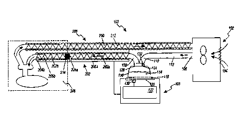
[0055] FIG. 1 illustrates an example respiratory humidification
system 100 for
delivering humidified gas to a user, the respiratory humidification system 100
having a
breathing circuit 200 that includes a segmented inspiratory limb 202 with
sensors 204a, 204b
in each segment. The segmented inspiratory limb 202 can be used in conjunction
with an
incubator 208, as illustrated, or with another system where there are
different temperatures
along different segments of the inspiratory limb 202, such as in conjunction
with a radiant
warmer. The segmented inspiratory limb 202 can be used to provide different
levels of heat
to different segments of the inspiratory limb 202a, 202b to reduce or prevent
condensation
and/or to control a temperature of gas delivered to a user.
[0056] The illustrated respiratory humidification system 100
comprises a
pressurized gas source 102. In some implementations, the pressurized gas
source 102
comprises a fan, blower, or the like. In some implementations, the pressurized
gas source
102 comprises a ventilator or other positive pressure generating device. The
pressurized gas
source 102 comprises an inlet 104 and an outlet 106.
[0057] The pressurized gas source 102 provides a flow of fluid
(e.g., oxygen,
anesthetic gases, air or the like) to a humidification unit 108. The fluid
flow passes from the
outlet 106 of the pressurized gas source 102 to an inlet 110 of the
humidification unit 108. In
the illustrated configuration, the humidification unit 108 is shown separate
of the pressurized
gas source 102 with the inlet 110 of the humidification unit 108 connected to
the outlet 106
-18-
Date Recue/Date Received 2021-03-10
of the pressurized gas source 102 with a conduit 112. In some implementations,
the
pressurized gas source 102 and the humidification unit 108 can be integrated
into a single
housing.
[0058] While other types of humidification units can be used with
certain
features, aspects, and advantages described in the present disclosure, the
illustrated
humidification unit 108 is a pass-over humidifier that comprises a
humidification chamber
114 and an inlet 110 to the humidification chamber 114. In some
implementations, the
humidification chamber 114 comprises a body 116 having a base 118 attached
thereto. A
compartment can be defined within the humidification chamber 116 that is
adapted to hold a
volume of liquid that can be heated by heat conducted or provided through the
base 118. In
some implementations, the base 118 is adapted to contact a heater plate 120.
The heater plate
120 can be controlled through a controller 122 or other suitable component
such that the heat
transferred into the liquid can be varied and controlled.
[0059] The controller 122 of the humidification unit 108 can control
operation of
various components of the respiratory humidification system 100. While the
illustrated
system is illustrated as using a single controller 122, multiple controllers
can be used in other
configurations. The multiple controllers can communicate or can provide
separate functions
and, therefore, the controllers need not communicate. In some implementations,
the
controller 122 may comprise a microprocessor, a processor, or logic circuitry
with associated
memory or storage that contains software code for a computer program. In such
implementations, the controller 122 can control operation of the respiratory
humidification
system 100 in accordance with instructions, such as contained within the
computer program,
and also in response to internal or external inputs. The controller 122, or at
least one of the
multiple controllers, can be located with the breathing circuit, either
attached to the breathing
circuit or integrated as part of the breathing circuit.
[0060] The body 116 of the humidification chamber 114 comprises a
port 124
that defines the inlet 110, and a port 126 that defines an outlet 128 of the
humidification
chamber 114. As liquid contained within the humidification chamber 114 is
heated, liquid
vapor is mixed with gases introduced into the humidification chamber 114
through the inlet
port 124. The mixture of gases and vapor exits the humidification chamber 114
through the
outlet port 126.
-19-
Date Recue/Date Received 2021-03-10
[0061] The respiratory humidification system 100 includes a
breathing circuit 200
comprising the inspiratory limb 202 connected to the outlet 128 that defines
the outlet port
126 of the humidification unit 108. The inspiratory limb 202 conveys toward a
user the
mixture of gases and water vapor that exits the humidification chamber 114.
The inspiratory
limb 202 can include a heating element 206 positioned along the inspiratory
limb 202,
wherein the heating element 206 is configured to reduce condensation along the
inspiratory
limb 202, to control a temperature of gas arriving at the user, to maintain
humidity of the gas,
or any combination of these. The heating element 206 can raise or maintain the
temperature
of the gases and water vapor mixture being conveyed by the inspiratory limb
202. In some
implementations, the heating element 206 can be a wire that defines a
resistance heater. By
increasing or maintaining the temperature of the gases and water vapor mixture
leaving the
humidification chamber 114, the water vapor is less likely to condensate out
of the mixture.
[0062] The respiratory humidification system 100 can be used in
conjunction with
an incubator 208. The incubator 208 can be configured to maintain a desired
environment
for a user within the incubator 208, such as a selected, defined, or desired
temperature.
Within the incubator 208, therefore, an interior ambient temperature may be
different than a
temperature outside the incubator 208. Thus, the incubator 208 causes,
defines, creates, or
maintains different temperature zones along the inspiratory limb 202, where
the interior
temperature is typically hotter than the exterior temperature. Having at least
two different
temperature zones along the inspiratory limb 202 can create problems during
delivery of gas
to a user such as condensation along the inspiratory limb 202, delivering a
gas that has a
temperature that is too high, or both.
[0063] The respiratory humidification system 100 can include an
expiratory limb
210 with associated heating element 212. In some embodiments, the expiratory
limb 210 and
the inspiratory limb 202 can be connected using a suitable fitting (e.g., a
wye-piece). In
some embodiments, the respiratory humidification system 100 can be used in
conjunction
with a radiant warmer, under a blanket, or in other systems or situations that
create two or
more temperature zones. The systems and methods described herein can be used
with such
systems and are not limited to implementations incorporating incubators.
[0064] The inspiratory limb 202 can be divided into segments 202a
and 202b
where a first segment 202a can be a portion of the inspiratory limb 202 that
is outside the
-20-
Date Recue/Date Received 2021-03-10
incubator 208 and a second segment 202b (e.g., an incubator extension), can be
a portion of
the inspiratory limb 202 that is inside the incubator 208. The first and
second segments 202a,
202b can be different lengths or the same length. In some embodiments, the
second segment
202b can be shorter than the first segment 202a, and, in certain
implementations, the second
segment 202b can be about half as long as the first segment 202a. The first
segment 202a,
for example, can have a length that is at least about 0.5 m and/or less than
or equal to about
2 m, at least about 0.7 m and/or less than or equal to about 1.8 m, at least
about 0.9 m and/or
less than or equal to about 1.5 m, or at least about 1 m and/or less than or
equal to about
1.2 m. The second segment 202b, for example, can have a length that is at
least about 0.2 m
and/or less than or equal to about 1.5 m, at least about 0.3 m and/or less
than or equal to
about 1 m, at least about 0.4 m and/or less than or equal to about 0.8 m, or
at least about
0.5 m and/or less than or equal to about 0.7 m.
[0065]
The segments of the inspiratory limb 202a, 202b can be coupled to one
another to form a single conduit for gas delivery. In some embodiments, the
first segment
202a can include one or more first heater wires 206a and one or more first
sensors 204a and
can be used without the second segment 202b. The controller 122 can be
configured to
control the first heater wires 206a and read the first sensor 204a without the
second segment
202b being coupled to the first segment 202a. Furthermore, when the second
segment 202b
is coupled to the first segment 202a, the controller 122 can be configured to
control the first
and second heater wires 206a, 206b and read the first and second sensors 204a,
204b in their
respective segments. In some embodiments, the controller 122 can be configured
to control
the respective first and second heater wires 206a, 206b and to read the
respective first and
second sensors 204a, 204b when the second segment 202b is attached; and to
control the first
heater wires 206a and to read the first sensor 204a when the second segment
202b is not
attached, without modification to the controller 122 or humidification unit
108. Thus, the
same controller 122 and/or humidification unit 108 can be used whether the
inspiratory limb
202 includes both the first and second segments 202a, 202b or only the first
segment 202a.
In some embodiments, the controller 122 can be further configured to control
the heater
wires 212 in the expiratory limb 210 without modification to the controller
122 or
humidification unit 108. Accordingly, the respiratory humidification system
100 can
-21-
Date Recue/Date Received 2021-03-10
function with or without the second segment 202b attached and/or with or
without the
expiratory limb 210 attached.
[0066] In
some embodiments, the first and second segments 202a, 202b are
permanently joined together to form a single conduit for gas delivery. As used
here,
permanently joined can mean that the segments 202a, 202b are joined together
in a manner
that makes it difficult to separate the segments, such as through the use of
adhesives, friction
fits, over-molding, mechanical connectors, and the like. In some embodiments,
the first and
second segments 202a, 202b are configured to be releasably coupled. For
example, the first
segment 202a can be used for gas delivery without the second segment 202b, or
the first and
second segments 202a, 202b can be coupled together to form a single conduit
for gas
delivery. In some embodiments, the first and second segments 202a, 202b can be
configured
such that they can be coupled together in only one configuration. For example,
the first
segment 202a can have a defined chamber-end (e.g., an end closest to the
chamber 114 or
humidification unit 108 along a direction of the flow of the humidified gas to
the patient) and
a defined patient-end (e.g., an end closest to the patient along a direction
of the flow of the
humidified gas to the patient) wherein the chamber-end is configured to couple
to
components at the chamber 114 and/or humidification unit 108. The second
segment 202b
can have a defined chamber-end and a defined-patient end wherein the chamber-
end is
configured to only couple to the patient-end of the first segment 202a. The
chamber-end of
the first segment 202a can be configured to not couple with either end of the
second segment
202b. Similarly, the patient-end of the first segment 202a can be configured
to not couple
with the patient-end of the second segment 202b. Similarly, the patient-end of
the second
segment 202b can be configured to not couple with either end of the first
segment 202a.
Accordingly, the first and second segments 202a, 202b can be configured to be
coupled in
only one way to form a single conduit for gas delivery. In some embodiments,
the first and
second segments 202a, 202b can be configured to be coupled in a variety of
configurations.
For example, the first and second segments 202a, 202b can be configured to not
include a
defined patient-end and/or a defined chamber-end. As another example, the
first and second
segments 202a, 202b can be configured such that the patient-end and/or the
chamber-end of
the first segment 202a can couple to either the chamber-end or the patient-end
of the second
segment 202b. Similarly, the first and second segments 202a, 202b can be
configured such
-22-
Date Recue/Date Received 2021-03-10
that the chamber-end and/or the patient-end of the second segment 202a can
couple to either
the chamber-end or the patient-end of the second segment 202b.
[0067]
The respiratory humidification system 100 can include an intermediate
connector 214 that can be configured to electrically couple elements of the
first and second
segments 202a, 202b of the inspiratory limb 202. The intermediate connector
214 can be
configured to electrically couple the heater wires 206a in the first segment
202a to the heater
wires 206b in the second segment 202b to enable control of the heater wires
206a, 206b
using the controller 122. The intermediate connector 214 can be configured to
electrically
couple the second sensor 204b in the second segment 202b to the first sensor
204a in the first
segment to enable the controller 122 to acquire their respective outputs. The
intermediate
connector 214 can include electrical components that enable selective control
of the heater
wires 206a, 206b and/or selective reading of the sensors 204a, 204b. For
example, the
intermediate connector 214 can include electrical components that direct power
through the
first heater wires 206a in a first mode and through the first and second
heater wires 206a,
206b in a second mode. The electrical components included on the intermediate
connector
214 can include, for example and without limitation, resistors, diodes,
transistors, relays,
rectifiers, switches, capacitors, inductors, integrated circuits, micro-
controllers, micro-
processors, RFID chips, wireless communication sensors, and the like. In
some
embodiments, the intermediate connector 214 can be configured to be internal
to the
inspiratory limb 202 such that it is substantially shielded from external
elements (e.g., less
than 1% of the water, particulates, contaminates, etc. from an environment
external to the
inspiratory limb 202 contacts the intermediate connector 214). In some
embodiments, some
of the electrical components on the intermediate connector 214 can be
configured to be
physically isolated from the humidified gas within the inspiratory limb 202 to
reduce or
prevent damage that may result from exposure to humidity. In some embodiments,
the
intermediate connector 214 can include relatively inexpensive passive
electrical components
to reduce cost and/or increase reliability.
[0068]
The inspiratory limb 202 can include sensors 204a, 204b in respective
segments of the inspiratory limb 202a, 202b. The first sensor 204a can be
positioned near an
end of the first segment 202a, close to the incubator 208 so that the
parameter derived from
the first sensor 204a corresponds to a parameter of the humidified gas
entering the second
-23-
Date Recue/Date Received 2021-03-10
segment 202b. The second sensor 204b can be positioned near an end of the
second segment
202b so that the parameter derived from the second sensor 204b corresponds to
a parameter
of the humidified gas delivered to the patient or user. The output of the
sensors 204a, 204b
can be sent to the controller 122 as feedback for use in controlling power
delivered to the
heating elements 206a, 206b of the segments of the inspiratory limb 202a,
202b. In some
embodiments, one or both of the sensors 204a, 204b can be temperature sensors,
humidity
sensors, oxygen sensors, flow sensors, or the like. A temperature sensor can
be any suitable
type of temperature sensor including, for example and without limitation, a
thermistor,
thermocouple, digital temperature sensor, transistor, and the like. The
parameters provided
by or derived from the sensors can include, for example and without
limitation, temperature,
humidity, oxygen content, flow rate, or any combination of these or the like.
100691 The controller 122 can be configured to control the heater
wires 206a and
206b, to receive feedback from the sensors 204a and 204b, to provide logic to
control power
to the heater wires 206a and 206b, to adjust control of the heater wires 206a
and 206b in
response to readings from the sensors 204a and 204b, to detect a presence of a
second
segment 202b of the inspiratory limb 202, to derive parameters from the
readings from the
sensors 204a and 204b, and the like. In some embodiments, the controller 122
includes a
power source configured to deliver electrical power to the heater wires. The
power source
can be a source of alternating current or direct current. In some embodiments,
the controller
122 can receive input from a heater plate sensor 130. The heater plate sensor
130 can
provide the controller 122 with information regarding a temperature and/or
power usage of
the heater plate 120. In some embodiments, the controller 122 can receive
input from a flow
sensor 132. Any suitable flow sensor 132 can be used and the flow sensor 132
can be
positioned between ambient air and the humidification chamber 114 or between
the
pressurized gas source 102 and the humidification chamber 114. In the
illustrated system,
the flow sensor 132 is positioned on the inlet port 124 of the humidification
chamber 114.
Segmented Inspiratory Limbs
100701 FIG. 2 illustrates a portion of a segmented inspiratory limb
202 for use
with a respiratory humidification system 100, the segmented inspiratory limb
202 comprising
a first segment 202a and a second segment 202b and having an intermediate
connector 214
-24-
Date Recue/Date Received 2021-03-10
configured to couple first heater wires 206a to second heater wires 206b and a
first sensor
204a to a second sensor 204b in the respective segments 202a and 202b.
Coupling the two
segments 202a and 202b can comprise mechanically coupling the segments to form
a single
conduit through which humidified gases can be delivered to a user wherein
mechanically
coupling the segments 202a and 202b can result in electrically coupling the
respective heater
wires 206a, 206b and the respective sensors 204a, 204b through the
intermediate connector
214.
[0071] The segmented inspiratory limb 202 can comprise a structure
216 forming
a lumen through which humidified gases can pass. The structure 216 can include
paths
formed within walls of the structure 216 configured to house heater wires 206a
or 206b such
that the heater wires 206a or 206b are shielded from the humidified gases
travelling through
the lumen and/or are covered by an external surface of the structure 216 so
that they are not
exposed. For example, the structure 216 can be a spiral bubble tube wherein
the heater wire
paths are coils molded into the tube. The structure 216 can comprise any type
of suitable
material and can include insulating material and/or flexible material. In some
embodiments,
the structure 216 and the intermediate connector 214 can be configured such
that, when the
first and second segments 202a and 202b are mechanically coupled, the heater
wires 206a
and 206b wrap over the intermediate connector 214 in such a way as to be
electrically
coupled to the intermediate connector 214. In some embodiments, the first
segment 202a
and/or the intermediate connector 214 can exclude any flying leads for
connecting to the
second segment 202b, thereby facilitating connection of the second segment
202b to the first
segment 202a.
[0072] The structure 216 at complementary ends of the first and
second segments
202a and 202b can be configured to house the intermediate connector 214. Thus,
the
intermediate connector 214 can be internal to the inspiratory limb 202. In
some
embodiments, the complementary ends of the first and second segments 202a and
202b can
be configured to shield the intermediate connector 214 from humidified gases
travelling
through the inspiratory limb 202. In some embodiments, the intermediate
connector 214 is
both internal to the inspiratory limb 202 and shielded from humidified gases
in the conduit,
thereby reducing or eliminating exposure of electrical connections on the
intermediate
connector 214.
-25-
Date Recue/Date Received 2021-03-10
100731 In some embodiments, the first heater wires 206a can comprise
two wires
218 and 220 and the second heater wires 206b can comprise two wires 222 and
224. The two
wires 218 and 220 in the first segment 202a can be electrically coupled to one
another
through electrical components 228 wherein the electrical coupling creates an
electrical path
through the wire 218, at least a portion of the electrical components 228, and
the wire 220.
Similarly, the two wires 222 and 224 in the second segment 202b can be
electrically coupled
to one another through electrical components 228 and/or electrically shorted
together at an
end of the segment 202b opposite the intermediate connector 202b, such as
through a patient-
end connector (not shown) as described in greater detail herein with reference
to FIGS. 3A,
3B, 8A, 8B, 9, and 13. By coupling the wires 222 and 224 of the second segment
202b at the
intermediate connector 214, electrical connections at the patient-end of the
inspiratory limb
202 are reduced or eliminated which can reduce cost, system complexity, and/or
risk to the
patient.
100741 The intermediate connector 214 can be configured to allow a
single
controller to control power to the heater wires 206a, 206b, wherein the
controller can be the
humidifier controller 122 as described herein with reference to FIG. 1. In
some
embodiments, the humidifier controller 122 controls the heater wires without
any additional
control functionality located on the intermediate connector 214. For example,
the
intermediate connector 214 can include passive components without any logic
circuitry
wherein the passive components direct power to heater wires 206a and/or 206b
as selected by
the controller 122. This can allow the intermediate connector 214 to be
designed using
relatively inexpensive components and can reduce the complexity of the design.
100751 In some embodiments, heating of the two segments 202a and
202b can be
accomplished using a maximum of four wires in each segment 202a, 202b. For
example, in
the first segment 202a the four wires can include a first heater wire 218, a
second heater wire
220, a signal sensor wire 228, and a return sensor wire 230. In the second
segment 202b the
four wires can include a first heater wire 222, a second heater wire 224, a
signal sensor wire
232, and a return sensor wire 234. By coupling the second heater wires 222,
224 to the first
heater wires 218, 220 at connection points 226, and by coupling the second
sensor wires 232,
234 to the first sensor wires 228, 230 at connection points 226, a controller
can be configured
to provide power independently to the first heater wires 206a and the second
heater wires
-26-
Date Recue/Date Received 2021-03-10
206b and to read sensor data independently from the sensors 204a and 204b
without
including more than four wires in either segment 202a or 202b. In some
embodiments,
control of the heater wires 206a and 206b and reading of the sensors 204a and
204b can be
accomplished using less than four wires in each segment (e.g., using 3 wires
or using 2
wires) or using more than four wires in each segment (e.g., using 5 wires,
using 6 wires,
using 7 wires, using 8 wires, or using more than 8 wires).
100761
The intermediate connector 214 can include electrical components 228
configured to allow a controller 122 to selectively control heater wires 206a,
206b. The
controller 122 can be configured to control heating of the inspiratory limb
202 using two
modes wherein a first control mode comprises providing power to the heater
wires 206a in
the first segment, and a second control mode comprises providing power to the
heater wires
206a and 206b in the first and second segments 202a and 202b. Thus, the
controller 122 can
be configured to independently control heater wire sections. This ability
allows for the
controller 122 to control heating of the inspiratory limb 202 when the second
segment 202b
is not present by solely controlling the heating of the inspiratory limb
according to the first
control mode, thereby allowing for the respiratory humidification system 100
to be used in a
variety of circumstances without modifying the controller 122 or
humidification unit 108. In
some embodiments, the control modes can include a mode where power is
delivered only to
the heater wires 206b in the second segment 202b. In some embodiments, the
controller 122
includes an electrical power source that provides electrical current. The
first and second
control modes can be based at least in part on the voltage supplied by the
power source
wherein a positive voltage or positive current can trigger the first control
mode and a
negative voltage or a negative current can trigger the second control mode. In
some
embodiments, the power source provides rectified AC or DC power to the heater
wires 206a,
206b and a change in the rectification or polarity triggers a change in the
control mode. By
switching control modes, control of heating in the breathing circuit 200 can
be accomplished
with any power supply that can switch the polarity of the output signal. In
some
embodiments, the amount of power provided to the heater wires 206a, 206b can
be adjusted
by adjusting a duty cycle of power applied to the heater wires 206a, 206b. For
example,
pulse-width modulation (PWM) can be used to power the heater wires 206a, 206b
and the
duty cycle of the PWM signal can be adjusted to control the power delivered.
In another
-27-
Date Recue/Date Received 2021-03-10
example, the amount of power provided to the heater wires 206a, 206b can be
adjusted by
controlling the amplitude of the power signal.
[0077] The intermediate connector 214 can include electrical
components 230
configured to allow a controller 122 to selectively read sensors 204a, 204b.
Selective reading
can be accomplished through the use of a source of electrical current wherein
applying a
positive current across the wires 228 to 230 can result in the controller 122
measuring a
signal from the first sensor 204a and applying a negative current across the
wires 228 and
230 can result in the controller 122 measuring a signal from the second sensor
204b or from
both the first and second sensors 204a, 204b, as described herein with
reference to FIGS. 6A,
6B, and 7. The controller 122 can use the readings from the sensors 204a, 204b
to adjust
power to the heater wires 206a, 206b, using, for example pulse-width
modulation. The first
sensor 204a can be positioned near the connection or intersection of the first
and second
segments 202a and 202b to provide to the controller 122 a parameter of gases
entering the
second segment 202b, which can correspond to entering an incubator or other
such region
having a different ambient temperature. The second sensor 204b can be
positioned at a
patient-end of the second segment 202b to provide to the controller 122 a
parameter of gases
delivered to the patient or a parameter of gases prior to the final piece
before the patient, such
as a wye-piece. The controller 122 can use these readings to adjust power to
the heater wires
206a, 206b to maintain the temperature of the gas at the patient-end of the
inspiratory limb
202 at a targeted or suitable temperature. The targeted or suitable
temperature can vary
depending at least in part on the application and environment it is being used
in, and can be
about 37 C, about 40 C, at least about 37 C and/or less than or equal to
about 38 C, at least
about 36.5 C and/or less than or equal to about 38.5 C, at least about 36 C
and/or less than or
equal to about 39 C, at least about 35 C and/or less than or equal to about 40
C, at least about
37 C and/or less than or equal to about 41 C, or at least about 39.5 C and/or
less than or
equal to about 40.5 C. In some embodiments, the second sensor 204b can be
positioned
inside the incubator but not attached to the breathing circuit. By measuring
parameters inside
the incubator, the temperature of the second segment 202b can be calculated,
for example.
[0078] The controller 122 can independently control the amount of
power
delivered in the first and second control modes, as described herein. Based at
least in part on
feedback from the sensors 204a and/or 204b, the controller 122 can
independently adjust
-28-
Date Recue/Date Received 2021-03-10
power delivered in the first and second control modes, thereby resulting in
varying heater
power ratios between the first and second segments 202a and 202b.
[0079] In some embodiments, the first sensor 204a is positioned
within the flow
of gas within the inspiratory limb 202. In some embodiments, the intermediate
connector
214 or the first segment 202a can include a mechanical component that
decreases turbulence
in the flow of the gas across the first temperature sensor 204a which can
increase accuracy in
the readings of the sensor 204a. For example, the mechanical connector can
have an
aerodynamic cross section, examples of which are described for patient-end
connectors with
reference to FIGS. 15B-15E. In some embodiments, the mechanical component
(e.g., a
cross-member feature within the inspiratory conduit) that decreases turbulence
also secures
the sensor 204a within the flow of the gases. In some embodiments, the
intermediate
connector 214 and the mechanical component are configured to thermally isolate
the sensor
204a from the electrical components on the intermediate connector 214, which
may be
advantageous where the sensor 204a is a temperature sensor, for example.
[0080] In some embodiments, the intermediate connector 214 includes
additional
connection points in addition to the connection points 26 illustrated in FIG.
2. The additional
connection points can be used to incorporate further functionality into the
breathing circuit
such as, for example, incorporating a memory device (PROM), a micro-
controller, additional
circuits, and the like.
Intermediate Connector Circuits
[0081] FIG. 3A illustrates a circuit diagram of an example
intermediate connector
214 including an active rectified power source for providing power to heater
wires in a
segmented inspiratory limb of a breathing circuit, wherein the circuit is
configured to power
heater wires R1 and R2 in a first segment of the inspiratory limb in a first
mode and to power
heater wires R1, R2, R3, and R4 in both segments in a second mode. By
providing diodes
D1 and D2 on the intermediate connector 214 and switches Si and S2, power can
be
alternatively applied through heater wires R1 and R2, where the resistors
represent the heater
wires, or through heater wires R1, R2, R3, and R4.
[0082] The power source is represented in the figure using VP and VN
which
correspond to terminals of a power supply. In an embodiment, the voltage
supply is an
-29-
Date Recue/Date Received 2021-03-10
alternating current (AC) power supply. Alternatively, the power source can be
a direct
current (DC) power supply. Although described in this embodiment as diodes, D1
and D2
can include any of a plurality of different types of flow control devices such
as, for example
and without limitation, rectifiers, transistors, relays, switches, triacs,
mosfets, thyristors
(SCR), thermostats, and the like.
100831 The switches Si and S2 switch between the VP and VN terminals
of the
power source. In an embodiment, switches Si and S2 are switched every half-
cycle of an
AC power cycle so that approximately equal current is drawn from the power
source during
every half cycle. The circuit illustrated in FIG. 3A can be used to control
the heaters RI, R2,
R3, and R4 in two control modes, wherein a first control mode corresponds to
providing
power only to R1 and R2, and a second control mode corresponds to providing
power to R1,
R2, R3 and R4. To provide power only to the heaters RI and R2 in the first
segment 202a
(corresponding to the first control mode), switch Si connects to VP and switch
S2 connects
to VN during a positive cycle from the power source, and switch Si connects to
VN and
switch S2 connects to VP during a negative cycle from the power source. In the
first control
mode, current flows through R1, R2, and DI while D2 prevents current from
flowing through
R3 and R4. To provide power to the heaters R1, R2, R3, and R4 in the first and
second
segments 202a, 202b (corresponding to the second control mode), switch Si
connects to VN
and switch S2 connects to VP during a positive cycle from the power source,
and switch Si
connects to VP and switch S2 connects to VN during a negative cycle from the
power source.
In the second control mode, current flows through R1, R2, R3, R4 and D2 while
DI prevents
current from shorting across the wires to bypass heaters R3 and R4. Switching
of switches
Si and S2 can be accomplished through hardware or software that adds logic to
the system,
as described herein with reference to FIG. 5. In some embodiments, switching
of switches
Si and S2 is performed at the zero crossing of an AC power cycle. In some
embodiments,
the falling and rising edges of zero crossing circuitry are not delayed by the
same amount and
the circuit is not active near the zero crossing. Thus, the switching of
switches Si and S2 can
be performed with or without zero-crossing switching detection and/or logic.
100841 The diodes D1 and D2 can dissipate power in the circuit, and
therefore
generate heat. In some embodiments, Schottky diodes can be used where it is
desirable to
reduce power dissipation in relatively high-temperature environments. Schottky
diodes can
-30-
Date Recue/Date Received 2021-03-10
be operated near a maximum junction temperature to reduce or minimize power
dissipation,
which may be desirable in certain implementations of the respiratory
humidification system
described herein. In some embodiments, the heat generated by the diode can
influence
temperature readings of the sensor 204a. To reduce this influence, the diodes
can be
thermally connected to an airflow path of the circuit. To reduce this
influence and to
dissipate the heat generated by the diodes, a heat sink or pad can be included
on the
intermediate connector 214 that is thermally coupled to the ambient
environment. To reduce
this influence, and the influence of other components on the intermediate
connector 214, the
sensor 204a (e.g., a thermistor or other temperature sensor) can be thermally
insulated from
the components and physically located relatively far from the other
components, as described
with reference to FIGS. 14A¨B, and 15.
100851 FIG. 3B illustrates another circuit diagram of an example
intermediate
connector 214 including an active rectified power source for providing power
to heater wires
in a segmented inspiratory limb of a breathing circuit, wherein the circuit is
configured to
power heater wires RI and R2 in a first segment of the inspiratory limb in a
first mode and to
power heater wires R1, R2, R3, and R4 in both segments in a second mode. As
shown in
FIG. 3B, only diode D1 may be provided and the path of power through heater
wires R1 and
R2 or through heater wires R1 through R4 can still be controlled, as
previously described
with respect to FIG. 3A. The diode D2 that was shown in the circuit of FIG. 3A
is
eliminated. The circuit shown in FIG. 3B, having only one diode D1, can result
in less heat
generated by the circuit, reduced parts costs, and a smaller circuit board.
The remaining
portions of the circuit shown in FIG. 3B operate in a manner that is similar
to the description
of FIG. 3A. In embodiments without D2, as illustrated in Figure 3B, most of
the current
flows through R1, R2 and D1 with only residual current flowing through R3 and
R4. The
residual current through R3 and R4 can be negligible such that it does not
affect the
performance of the humidification system.
[0086] In addition to the AC operation described with respect to
FIGS. 3A and
3B, similar circuits can be operated with a DC supply. Switches 51 and S2 can
be switched
based at least in part on, for example, time, an output current of the supply,
feedback from
sensors, or other control inputs. In such an embodiment, the circuits
illustrated in FIGS. 3A
or 3B also can be used to control the heaters R1, R2, R3, and R4 in two
control modes,
-31 -
Date Recue/Date Received 2021-03-10
wherein a first control mode corresponds to providing power only to R1 and R2,
and a
second control mode corresponds to providing power to R1 through R4. To
provide power
only to the heaters RI and R2 in the first segment 202a (corresponding to the
first control
mode), switch Si connects to VP and switch S2 connects to VN. In the first
control mode,
current flows through R1, R2, and Dl. D2 prevents current from flowing through
R3 and R4
in the circuit shown in FIG. 3A. However, D2 is an optional component as shown
in FIG.
3B. To provide power to the heaters R1, R2, R3, and R4 in the first and second
segments
202a, 202b (corresponding to the second control mode), switch Si connects to
VN and
switch S2 connects to VP. In the second control mode, current flows through
RI, R2, R3,
R4, while D1 prevents current from shorting across the wires to bypass heaters
R3 and R4.
As previously described, switching can be accomplished through hardware or
software that
adds logic to the system, as described herein with reference to FIG. 5.
Control of Inspiratory and Expiratory Limb Heaters
100871 FIG. 1 also illustrates an example respiratory humidification
system 100
having an inspiratory limb 202 and an expiratory limb 210, wherein the
humidification
system 100 is configured to control heater wires 206, 212 in both limbs. In
some
embodiments, heater wires 212 in the expiratory limb 210 can be electrically
coupled to the
inspiratory heater wires 206 outside the humidification unit 108 and
controller 122 so that
control of the expiratory heater wires 212 can be implemented without
affecting other control
modes and without additional switching transistors. Similarly, the expiratory
heater wires
212 can be electrically coupled to the inspiratory heater wires 206 within the
humidification
unit 108. Connection of the expiratory heater wires 212 to the inspiratory
heater wires 206
can be done in the humidification system 108, on the intermediate connector
214, in a sensor
cartridge at the humidification system 108, or the like. Thus, the controller
122 can control
the expiratory heater wires 212 with no additional electrical connections at
the patient end,
the presence of which may increase risk, system complexity, and cost. Examples
of
electrical coupling of the expiratory heater wires 212 and the inspiratory
heater wires 206
inside the humidification unit 108 are shown in FIGS. 4A-4D, 8A, and 8B.
100881 With reference to FIG. 4A, the humidification unit 108 can
incorporate
switches or relays S3 and S4 to select between independent and dependent
control of the
-32-
Date Recue/Date Received 2021-03-10
inspiratory heater wires and the expiratory heater wires. In some embodiments,
the switches
or relays are activated when a tube (e.g., an inspiratory limb or an
expiratory limb) with an
appropriate identification is connected to the humidification unit 108, such
as through an
identification resistor detected and/or measured by the humidification unit
108. For example,
when the switches are not activated (e.g., both switches S3, S4 are open), the
heater wires in
the inspiratory limb and/or the heater wires in the expiratory limb can be
individually and/or
independently controlled.
[0089]
When an appropriate tube is connected or the system otherwise determines
it is appropriate, the switches S3 and S4 can be closed to simultaneously
control the
inspiratory limb and the expiratory limb. The humidification unit 108 can
include an
inspiratory power source INSP and an expiratory power source EXP, wherein the
system can
implement switching in each power source as described herein with reference to
FIGS. 3A
and 3B. For example, with reference to FIG. 3A, the inspiratory power source
can have
switches Si and S2 configured to selectively direct positive and negative
cycles to the heaters
R1 through R4. Similarly, with reference to FIG. 4A, the expiratory power
source EXP can
include switches configured to selectively direct power to the expiratory limb
having heaters
R5 and R6. In some embodiments, when switches S3 and S4 are closed, both
switches in
expiratory power source EXP can be opened such that power is provided to the
inspiratory
heater wires and the expiratory heater wires by the inspiratory power source
INSP. In some
embodiments, the humidification unit 108 does not include an expiratory power
source EXP.
In such embodiments, the inspiratory power source INSP is used to provide
power to the
inspiratory heater wires when the switches S3 and S4 are open and to provide
power to both
the inspiratory and expiratory heater wires when the switches S3 and S4 are
closed. Thus,
the inspiratory limb heater wires 206 can be controlled in the same way as
before, but now
the system can use the switches S3, S4 to simultaneously control power to the
expiratory
heater wires 212 and the inspiratory heater wires 206 using a unified
electrical circuit and/or
control system. By way of example, the humidification unit 108 can operate in
two modes
relative to the inspiratory limb 202 (e.g., the first mode being where the
humidification unit
108 provides power to the heaters R1 and R2 and the second mode being where it
provides
power to the heaters R1 to R4) while selectively controlling power to the
heaters R5 and R6
in the expiratory limb such that the humidification unit 108 can provide no
power to the
-33-
Date Recue/Date Received 2021-03-10
heaters R5 and R6, or provide power to the heaters R5 and R6 while operating
in the first
mode, in the second mode, or in both modes. As previously described, a
connection between
the inspiratory limb 202 and expiratory limb 210 can be made internal or
external to the
humidification unit 108. In an embodiment, the connection is made in a sensor
cartridge, the
intermediate connector 214, or in another location.
[0090] In some embodiments, an expiratory circuit configured to
connect the
expiratory heater wires 212 to the controller 122 can be implemented at the
intermediate
connector 214 shown on FIG. 1. The expiratory circuit can be connected in one
or more of
several ways. For example, the expiratory circuit can be connected in parallel
with the heater
wires 206a in the first segment 202a or with the heater wires 206b in the
second segment
202b. In some embodiments, the intermediate connector 214 can include an
internal fly lead
making the expiratory circuit available on the intermediate connector 214. In
some
embodiments, the intermediate connector 214 can be connected to an added third
channel to
so that there are no fly leads between the inspiratory and expiratory
circuits. A heater wire
driver control circuit can be added to the controller 122 to accommodate such
embodiments.
[0091] FIG. 4B illustrates an example embodiment of a humidification
system
incorporating a power supply 405 to provide power to both the inspiratory
heater wires R1 to
R4 and the expiratory heater wires R5 and R6 through a combination of switches
or relays S1
to S6 and diode DI. In the illustrated embodiment, the humidification system
is configured
to provide power to the expiratory heater wires when only the inspiratory
heater wires RI, R2
in the first segment of the inspiratory limb are receiving power (e.g., in a
first operation
mode) or when the inspiratory heater wires R1 to R4 in both segments are
receiving power
(e.g., in a second operation mode). The power supply 405 can be any suitable
power supply
including, for example, a power supply which provides alternating current in a
sine wave,
sawtooth, square wave, or other form. In some embodiments, the power supply
405 is a
transformer which provides an alternating current signal with a voltage of at
least about
22 VAC, at least about 5 VAC or less than or equal to about 30 VAC, at least
about 10 VAC
or less than or equal to about 25 VAC, at least about 12 VAC or less than or
equal to about
22 VAC.
[0092] With continued reference to FIG. 4B, the humidification
system can be
configured to provide power to the expiratory heater wires R5, R6 in the first
operation mode
-34-
Date Recue/Date Received 2021-03-10
while the power supply 405 is providing power in a negative cycle. To do so,
switches Si,
S2, S5, S6 close and switches S3, S4 open. The current flows from the negative
terminal of
the power supply 405 through switch S2 and branches to provide power to the
heater wires in
both the inspiratory limb and the expiratory limb. In the inspiratory limb,
the current flows
to inspiratory heater wire R2, then through diode D1 to inspiratory heater
wire R1, and then
returns to the positive terminal on the power supply 405 through switch Si. In
the expiratory
limb, the current flows through switch S6 to expiratory heater wire R5, then
to expiratory
heater wire R6, and then returns to the positive terminal on the power supply
405 through
switches S5 and Si.
[0093] Similarly, with continued reference to FIG. 4B, the
humidification system
can be configured to provide power to the expiratory heater wires R5, R6 in
the first
operation mode while the power supply 405 is providing power in a positive
cycle. To do so,
switches S3, S4, S5, S6 close and switches Si, S2 open. The current flows from
the positive
terminal of the power supply 405 through switch S3 and branches to provide
power to the
heater wires in both the inspiratory limb and the expiratory limb. In the
inspiratory limb, the
current flows through switch S6 to inspiratory heater wire R2, then through
diode D1 to
inspiratory heater wire R1, and then returns to the negative terminal on the
power supply 405
through switches S5 and S4. In the expiratory limb, the current flows to
expiratory heater
wire R5, then to expiratory heater wire R6, and then returns to the negative
terminal on the
power supply 405 through switch S4.
[0094] With continued reference to FIG. 4B, the humidification
system can be
configured to provide power to the expiratory heater wires R5, R6 in the
second operation
mode while the power supply 405 is providing power in a positive cycle. To do
so, switches
Si, S2, S5, S6 close and switches S3, S4 open. The current flows from the
positive terminal
of the power supply 405 through switch Si and branches to provide power to the
heater wires
in both the inspiratory limb and the expiratory limb. In the inspiratory limb,
the current
flows to inspiratory heater wire R1, then bypasses diode D1 to flow to
inspiratory heater wire
R3, then to inspiratory heater wire R4, then to inspiratory heater wire R2,
and then returns to
the negative terminal on the power supply 405 through switch S2. In the
expiratory limb, the
current flows through switch S5 to expiratory heater wire R6, then to
expiratory heater wire
-35-
Date Recue/Date Received 2021-03-10
R5, and then returns to the negative terminal on the power supply 405 through
switches S6
and S2.
[0095] Similarly, with continued reference to FIG. 4B, the
humidification system
can be configured to provide power to the expiratory heater wires R5, R6 in
the second
operation mode while the power supply 405 is providing power in a negative
cycle. To do
so, switches S3, S4, S5, S6 close and switches Si, S2 open. The current flows
from the
negative terminal of the power supply 405 through switch S4 and branches to
provide power
to the heater wires in both the inspiratory limb and the expiratory limb. In
the inspiratory
limb, the current flows through switch S5 to inspiratory heater wire RI, then
bypasses diode
D1 to flow to inspiratory heater wire R3, then to inspiratory heater wire R4,
then to
inspiratory heater wire R2, and then returns to the positive terminal on the
power supply 405
through switches S6 and S3. In the expiratory limb, the current flows to
expiratory heater
wire R6, then to expiratory heater wire R5, and then returns to the positive
terminal on the
power supply 405 through switch S3.
[0096] FIG. 4C illustrates an example embodiment of a humidification
system
incorporating a power supply 405 to provide power to both the inspiratory
heater wires R1 to
R4 and the expiratory heater wires R5 and R6 through a combination of switches
or relays Si
to S6 and diodes D1, D2. In the illustrated embodiment, the humidification
system is
configured to provide power to the expiratory heater wires only when the
inspiratory heater
wires R1, R2 in the first segment of the inspiratory limb are receiving power
(e.g., only in the
first operation mode).
[0097] With continued reference to FIG. 4C, the humidification
system can be
configured to provide power to the expiratory heater wires R5, R6 in the first
operation mode
while the power supply 405 is providing power in a negative cycle. To do so,
switches Si,
S2, S5, S6 close and switches S3, S4 open. The current flows from the negative
terminal of
the power supply 405 through switch S2 and branches to provide power to the
heater wires in
both the inspiratory limb and the expiratory limb. In the inspiratory limb,
the current flows
to inspiratory heater wire R2, then through diode Dl to inspiratory heater
wire R1, and then
returns to the positive terminal on the power supply 405 through switch Si. In
the expiratory
limb, the current flows through switch S6 and through diode D2 to expiratory
heater wire R5,
-36-
Date Recue/Date Received 2021-03-10
then to expiratory heater wire R6 and then returns to the positive terminal on
the power
supply 405 through switches S5 and Si.
[0098] Similarly, with continued reference to FIG. 4C, the
humidification system
can be configured to provide power to the expiratory heater wires R5, R6 in
the first
operation mode while the power supply 405 is providing power in a positive
cycle. To do so,
switches S3, S4, S5, S6 close and switches Si, S2 open. The current flows from
the positive
terminal of the power supply 405 through switch S3 and branches to provide
power to the
heater wires in both the inspiratory limb and the expiratory limb. In the
inspiratory limb, the
current flows through switch S6 to inspiratory heater wire R2, then through
diode DI to
inspiratory heater wire RI, and then returns to the negative terminal on the
power supply 405
through switches S5 and S4. In the expiratory limb, the current flows through
diode D2 to
expiratory heater wire R5, then to expiratory heater wire R6, and then returns
to the negative
terminal on the power supply 405 through switch S4.
100991 With continued reference to FIG. 4C, the humidification
system can be
configured to provide power only to the inspiratory heater wires RI to R4 (and
not to provide
power to the expiratory heater wires R5, R6) in the second operation mode
while the power
supply 405 is providing power in a positive cycle. To do so, switches Si, S2,
S5, S6 close
and switches S3, S4 open. The current flows from the positive terminal of the
power supply
405 through switch Si to inspiratory heater wire R1, the current then bypasses
diode D1 and
flows to inspiratory heater wire R3, to inspiratory heater wire R4, to
inspiratory heater wire
R2 and back to the negative terminal on the power supply 405 through switch
S2. The
current does not flow through the expiratory heater wires because of diode D2
which blocks
the flow of current through that circuit on a positive cycle with the switches
configured as
described.
101001 Similarly, with continued reference to FIG. 4C, the
humidification system
can be configured to provide power only to the inspiratory heater wires R1 to
R4 (and not to
provide power to the expiratory heater wires R5, R6) in the second operation
mode while the
power supply 405 is providing power in a negative cycle. To do so, switches
S3, S4, S5, S6
close and switches Si, S2 open. The current flows from the positive terminal
of the power
supply 405 through switches S4 and S5 to inspiratory heater wire R1, the
current then
bypasses diode D1 and flows to inspiratory heater wire R3, to inspiratory
heater wire R4, to
-37-
Date Recue/Date Received 2021-03-10
inspiratory heater wire R2 and back to the negative terminal on the power
supply 405
through switches S6 and S3. The current does not flow through the expiratory
heater wires
because of diode D2 which blocks the flow of current through that circuit on a
negative cycle
with the switches configured as described.
101011 FIG. 4D illustrates an example embodiment of a humidification
system
incorporating a power supply 405 to provide power to both the inspiratory
heater wires R1 to
R4 and the expiratory heater wires R5 and R6 through a combination of switches
or relays Si
to S6 and diode DI with the expiratory heater wires R5, R6 being electrically
coupled to the
inspiratory heater wires RI to R4 on a patient-side of the heater wires in the
first segment of
the inspiratory limb, which can occur an intermediate connector, such as any
of the
intermediate connectors described herein. As described with reference to FIG.
4D, the
expiratory heater wires R5, R6 are coupled to the inspiratory heater wires RI
to R4 at the
intermediate connector, but any suitable location after the inspiratory heater
wires in the first
segment can be used for coupling the heater wires in the inspiratory and
expiratory limb. In
the illustrated embodiment, the humidification system is configured to provide
power to the
expiratory heater wires only when the inspiratory heater wires RI to R4 in
both segments of
the inspiratory limb are receiving power (e.g., only in the second operation
mode).
101021 With continued reference to FIG. 4D, the humidification
system can be
configured to provide power to the inspiratory heater wires R1 to R4 and to
the expiratory
heater wires R5, R6 in the second operation mode while the power supply 405 is
providing
power in a positive cycle. To do so, switches S I, S2, S5, S6 close and
switches S3, S4 open.
The current flows from the positive terminal of the power supply 405 through
switch S1 to
inspiratory heater wire R1, then bypasses diode D1 and branches to provide
power to the
heater wires in both the second segment of the inspiratory limb and the
expiratory limb. In
the second segment of the inspiratory limb, the current flows to inspiratory
heater wire R3,
then to inspiratory heater wire R4, returning to the intermediate connector.
In the expiratory
limb, current flows to R5 and then to R6, returning back to the intermediate
connector. The
current then flows through inspiratory heater wire R2 and then returns to the
negative
terminal on the power supply 405 through switch S2.
101031 Similarly, with continued reference to FIG. 4D, the
humidification system
can be configured to provide power to the expiratory heater wires R5, R6 in
the second
-38-
Date Recue/Date Received 2021-03-10
operation mode while the power supply 405 is providing power in a negative
cycle. To do
so, switches S3, S4, S5, S6 close and switches S 1, S2 open. The current flows
from the
negative terminal of the power supply 405 through switches S4 and S5 to
inspiratory heater
wire R1, then bypasses diode D1 and branches to provide power to the heater
wires in both
the second segment of the inspiratory limb and the expiratory limb. In the
second segment of
the inspiratory limb, the current flows to inspiratory heater wire R3, then to
inspiratory heater
wire R4, returning to the intermediate connector. In the expiratory limb,
current flows to R5
and then to R6, returning back to the intermediate connector. The current then
flows through
inspiratory heater wire R2 and then returns to the positive terminal on the
power supply 405
through switches S6 and S3.
101041 With continued reference to FIG. 4D, the humidification
system can be
configured to provide power only to the inspiratory heater wires RI and R2 in
the first
segment of the inspiratory limb (and not to provide power to the expiratory
heater wires R5,
R6) in the first operation mode while the power supply 405 is providing power
in a negative
cycle. To do so, switches SI, S2, S5, S6 close and switches S3, S4 open. The
current flows
from the negative terminal of the power supply 405 through switch S2 to
inspiratory heater
wire R2, the current then flows through diode D1 to inspiratory heater wire
R1, and then
returns to the positive terminal on the power supply 405 through switch Sl.
101051 Similarly, with continued reference to FIG. 4D, the
humidification system
can be configured to provide power only to the inspiratory heater wires R1 and
R2 in the first
segment of the inspiratory limb (and not to provide power to the expiratory
heater wires R5,
R6) in the first operation mode while the power supply 405 is providing power
in a positive
cycle. To do so, switches S3, S4, S5, S6 close and switches Sl, S2 open. The
current flows
from the positive terminal of the power supply 405 through switches S3 and S6
to inspiratory
heater wire R2, the current then flows through diode D1 to inspiratory heater
wire R1, and
returns back to the negative terminal on the power supply 405 through switches
S5 and S4.
Detecting a Connected Extension of an Inspiratory Limb
101061 FIG. 5 illustrates a block diagram of an example system 500
configured to
detect a presence of an extension of an inspiratory limb using extension
detect module 502
and to provide power to heater wires in the inspiratory limb (e.g., a first
segment of the
-39-
Date Recue/Date Received 2021-03-10
inspiratory limb), the extension of the inspiratory limb (e.g., a second
segment of the
inspiratory limb), and/or an expiratory limb. The logic module 504, which can
comprise
hardware, software, or some combination of both, can be configured to provide
the logic that
enables the switching described for the different control modes, as described
with reference
to, for example, FIGS. 3A, 3B, 4, 8A, and 8B. The logic module 504 can receive
signals
from an integrated circuit 506 that is part of the respiratory humidification
system 100. In
some embodiments, the logic module 504 is software embedded wholly or
partially within
the integrated circuit 506 which converts signals from the integrated circuit
506. The
combination of the logic module 504 and the integrated circuit 506 can be
configured to
detect a zero-level crossing, or where voltage or current transitions from
positive to negative
or vice versa, and to change states of switches according to a control mode.
The logic
module 504 can output PWM signals 508a, 508b according to a desired, selected,
or defined
power output where the PWM signal is delivered to the inspiratory heater wires
(INSP HW),
the expiratory heater wires (EXP HW), or both.
101071 In
some embodiments, the system 500 can include an extension detect
module 502 configured to detect whether the second segment 202b is connected
to the
breathing circuit 200. The extension detect module 502 can produce an "enable
signal" if the
second segment 202b is connected. The logic module 504 can receive the "enable
signal"
and adjust switching accordingly. In some embodiments, the "enable signal"
indicates to the
logic module 504 that the system 500 will not control the inspiratory and
expiratory circuits
independently and simultaneously.
101081 In
some embodiments, the extension detect module 502 can be configured
to detect the presence of the second segment 202b by switching on both the
inspiratory and
expiratory circuits and detecting whether a hardware overcurrent event is
detected. If the
overcurrent event is not detected when either are switched on individually but
it is detected
with they are both switched on together, the extension detect module 502 can
produce an
"enable signal" indicating that the second segment 202b is connected. In
some
embodiments, the extension detect module 502 can detect the presence of the
second segment
202b by detecting a resistance of an identification resistor or of heater
wires in each section
using current measurements. Based at least in part on the current measurements
of the
various sections, the extension detect module 502 can produce an "enable
signal" if current
-40-
Date Recue/Date Received 2021-03-10
measurements for different cycles differ where different control modes are
being
implemented as described above with reference to FIGS. 3A, 3B, 4, 8A, and 8B.
Sensor Circuits
101091 FIGS. 6A and 6B illustrate example circuit diagrams in a
respiratory
humidification system 100, wherein the circuit 600 is configured to read data
from two
sensors R1 and R2. With reference to FIGS. 6A and 6B, the sensors R1 and R2
are
represented using resistors, but any suitable type of sensor can be used such
as, for example
and without limitation, temperature sensors, humidity sensors, flow sensors,
oxygen sensors,
and the like. In some embodiments, the sensors can be temperature sensors such
as
thermistors. In such embodiments, the sensors R1 and R2 respectively represent
a first
thermistor at the intermediate connector 214 and a second thermistor at a
patient-end of the
breathing circuit 200 (e.g., on a patient-end connector). The two thermistors
R1 and R2 can
be measured using two wires in the breathing circuit 200 using the circuit 600
in conjunction
with a current or voltage source and switches in the humidifier controller
122. While the
description with reference to FIGS. 6A and 6B involves thermistors, it is
applicable to other
suitable sensors which affect voltages and/or currents provided to circuits
with which they
are associated.
101101 To selectively read the sensors R1 and R2, current is
supplied in either
polarity through lines 602 and 604. To measure the patient-end sensor R2, the
humidifier
controller 122 sets the switch to connect the top current supply to ground.
Current then flows
from the bottom current supply through R2 and to ground through the switch.
Current is
blocked from going through R1 by diode Dl. The humidifier controller 122 can
be
configured to measure the voltage drop from the bottom current supply to
ground, and to
derive the resistance of sensor R2 based at least in part on the supplied
current and measured
voltage. To measure the sensor R1 positioned at the intermediate connector
214, the
humidifier controller 122 can read the patient-end sensor R2 and record the
result. The
humidifier controller 122 can then set the switch to connect the bottom
current supply to
ground. Current then flows from the top current supply through R1 and R2 to
ground
through the switch. The humidifier controller 122 can be configured to measure
the voltage
drop from the top current supply to ground, and to derive the resistance of
sensor R1 based at
-41-
Date Recue/Date Received 2021-03-10
least in part on the supplied current, the measured voltage, and the recorded
result from
measuring the resistance of R2. In some embodiments, a voltage drop across D1
is
accounted for in the derivation of the resistance of Rl. In the embodiment
illustrated in FIG.
6A, by placing D1 near R1, the temperature of the diode D1 can be calculated
which can be
used in the calculation of the voltage drop across Dl. One potential advantage
of the
configuration illustrated in FIG. 6A is that the measurements of the sensor R2
at the patient
end may be more accurate because the measurements are made without passing
through a
diode, as illustrated in the embodiment of FIG. 6B, which can introduce
uncertainties or
errors.
[OM] In some embodiments, as illustrated in FIG. 6B, an additional
diode D2
can be added to the intermediate connector 214. In such embodiments, the
humidifier
controller 122 can be configured to measure sensors RI and R2 in a fashion
similar to the
embodiment illustrated in FIG. 6A and described above. A difference is that
when
measuring sensor R1, current flows through R1 and DI and not through R2
because the diode
D2 blocks current flow through R2. In this way, the measurement of sensor R1
can be
substantially isolated or separated from the measurement of sensor R2. Similar
to the
derivation of the resistance of sensor R1, the voltage drop across the diode
D2 can be
accounted for in deriving the resistance of sensor R2. By placing D1 and D2
near R1, the
temperature of the diodes can be calculated which can be used in the
calculation of the
voltage drops across D1 and D2, respectively.
[0112] In certain embodiments, the measurement of sensors R1, R2 is
performed
in software running in a controller connected to the circuits of FIGS. 6A or
6B. The
direction and amount of current supplied to the circuit can be controlled by
such software.
An accurate measurement of the resistance of sensors R1, R2 can be obtained by
measuring
the voltages using, for example, an analog to digital converter. To minimize
or eliminate the
effects of variances caused by the diodes D1 and/or D2, the software can
supply two different
currents (U. and 12) in the same direction. This will result in two different
voltage readings
(V1 and V2) corresponding to the two different currents (II and 12). Using
these two
voltages and currents, the software can solve for the voltage drop of the
diodes D1, D2 and
resistances for sensors R1, R2. For sensor R1, for example, the voltage drop
can be solved
with the following equation: Vdrop = ((V1*I2 ¨ V2*I1) / ((V1-V2) / R2 + 12 ¨
I1)). The
-42-
Date Recue/Date Received 2021-03-10
resistance of sensor R1 can be calculated using the following equation: R1 =
(V2 ¨ Vdrop) /
(12 ¨ V2 / R2). In an embodiment, the calculated Vdrop has a constant error
from a
measured Vdrop that is corrected in software. In an embodiment, the Vdrop is
increased by
approximately 15% as an error compensation.
[0113] FIG. 7 illustrates an example circuit diagram in the
respiratory
humidification system 100, wherein the circuit 700 is configured to read
temperature data
using two transistors Q1 and Q2 acting as temperature sensors. The temperature
measurement can be based at least in part on a temperature effect of the p11-
junction of the
base and emitter terminals of the transistors. The switching of the current in
the humidifier
controller 122 can be the same as for the circuit described with reference to
FIGS. 6A and 6B
or it can be an alternate configuration, as shown. For example, the
illustrated switching
configuration uses two switches with two power sources and two grounds to
selectively
provide electrical power to the wires. In a first configuration, the top
switch electrically
connects a top power source to wire 702 and the bottom switch electrically
connects the
ground to wire 704. In a second configuration, the top switch electrically
connects the
ground to wire 702 and the bottom switch electrically connects the bottom
power source to
wire 704. By using transistors Q1 and Q2 as temperature sensors, the diodes
can be removed
as the transistors provide the functionality of the temperature sensors and
the diodes.
Breathing Circuit Hardware Configurations
[0114] FIG. 8A illustrates an example diagram of a hardware
configuration 800
for a breathing circuit 200 having a first segment of an inspiratory limb
202a, a second
segment of the inspiratory limb 202b, and an expiratory limb 210. The hardware
configuration 800 can include a humidifier 108 configured to couple the wiring
of the heater
wires HW1 and HW2 through switches or relays S3 and S4, and the wiring for
sensors 204a,
204b. In some embodiments, the sensor cartridge 802 can be configured to
couple the wiring
of the heater wires HW1, HW2 and the wiring for sensors 204a, 204b. The
switches S3, S4
can be used to selectively control power to the heater wires HW2 of the
expiratory limb 210,
as described with reference to FIG. 4A with similar functionality described
with reference to
FIGS. 4B-4D. In some embodiments, the switches S3 and S4 both default to an
open
position, and are closed when an appropriate tube is connected to the
humidifier 108 (e.g., an
-43-
Date Recue/Date Received 2021-03-10
inspiratory limb or expiratory limb with an appropriate identification
resistor). In this way,
the hardware configuration 800 can be used to provide power to heater wires
HW1 and/or to
heater wires HW2. Independent of whether the heater wires HW2 are receiving
electrical
power, the heater wires HW1 can be controlled in two modes. In a first mode,
the first heater
wires 206a receive electrical power while the second heater wires 206b do not.
In a second
mode, the first and second heater wires 206a, 206b receive electrical power.
In the illustrated
embodiment, heater wires HW2 are able to be powered when the heater wires HW1
are being
controlled in either of the first or second modes. It is to be understood that
the heater wires
HW2 of the expiratory limb can be selectively controlled while the heater
wires HW1 of the
inspiratory limb remain in a single mode. For example, when the heater wires
HW1 of the
inspiratory limb are being controlled in a first mode (or a second mode), the
heater wires
HW2 of the expiratory limb can alternately receive or not receive power based
at least in part
on the operation of switches S3 and S4 without any change in control mode of
the heater
wires HW1. Similarly, the heater wires HW2 of the expiratory limb can remain
receiving
power while the heater wires HW1 of the inspiratory limb are changed between
the first and
second modes.
[0115] The hardware configuration 800 can include an intermediate
printed
circuit board (PCB) 214 that includes two diodes, with one diode being a power
diode D1
and another diode being a signal diode D3. The intermediate PCB 214 can
include heat pads
to dissipate heat generated by the diodes D1, D3 to reduce the effects on the
sensor 204a.
The hardware configuration 800 can include a patient-end PCB 804 having two
heater wires
and a sensor 204b, wherein the heater wires 206b are directly electrically
coupled. In the
first mode of operation, electrical power can be provided to 11W1 such that
current flows
through heater wires 206a and through diode D1 while substantially no current
flows through
heater wires 206b (e.g., less than 1% of the current through heater wires 206a
flows through
heater wires 206b). In the second mode of operation, electrical power can be
provided to
HW1 such that current flows through heater wires 206a and 206b. The first and
second
modes of operation can be controlled at least in part by the direction of the
current flow
through the heater wires HW1.
[0116] In certain embodiments, diodes D2 and D4 can be added to
hardware
configuration 800, as shown in FIG. 8B. In such an embodiment, the software
for the
-44-
Date Recue/Date Received 2021-03-10
sensing circuit can be altered to account for increased heat. In some
embodiments, the signal
diodes D3, D4 are positioned close to one another so they experience the same
or similar
ambient conditions to reduce differential effects caused by differing ambient
temperatures.
The circuit 200 otherwise operates in a manner similar to the circuit shown in
FIG. 8A.
[0117] In some embodiments, comparing FIG. 8A to FIG. 8B, removing
diode
D4 improves patient end sensing reliability. For example, diodes can fail in
an open position.
If diode D4 fails open, reading the patient end temperature may not be
possible. In the
circuit shown in FIG. 8A, if diode D3 fails, the patient-end sensor 204b can
still be read. The
removal of diode D2 can have similar advantages.
[0118] In some embodiments, the sensor cartridge 802 can be located
within the
humidification system 100 or external to the system.
Example Segmented Inspiratory Limb with a Connector having a Micro-controller
[0119] FIG. 9 illustrates an example embodiment of a respiratory
humidification
system 100 that utilizes a micro-controller in an intermediate connector 214
to measure data
for controlling heating and to read sensor values in an inspiratory limb 202.
In some
embodiments, one or more micro-controllers can be incorporated in a sensor
cartridge, in the
humidifier, in the intermediate connector 214, or in any combination of these.
The micro-
controller provides similar functionality as described herein when
incorporated on the sensor
cartridge, for example. The illustrated example embodiment uses one heater
wire as a
common reference, the wire connected to VN, and connects the two heater wires
HW I, HW2
and the sensor wires to the common reference. The example embodiment also
converts both
sensors' 204a, 204b readings into a digital signal in the intermediate
connector 214 to send to
the humidifier controller 122. This can reduce or eliminate isolation issues
by referencing
the sensors 204a, 204b to a common reference point and by sending a digital
parameter
reading which can be passed through an optocoupler on the controller 122 which
will isolate
the signal, as described herein with reference to FIG. 12. Using this example
embodiment
can allow for two independent channels of control to heat just the first
section 202a or the
first and second sections of the inspiratory limb 202a, 202b to provide a
desired, selected, or
defined heating control.
-45-
Date Recue/Date Received 2021-03-10
[0120] FIG. 10 illustrates a block diagram of an intermediate
connector 214 for
an inspiratory limb 202, wherein the intermediate connector 214 uses a micro-
controller.
The micro-controller can be used to measure an analog signal from the
thermistors 204a and
204b and convert the analog signal into a digital signal using analog-to-
digital converters
(ADCs). The converted digital signal can be sent to the humidifier controller
122 on a single
data line. The data line can be used to allow communication between the micro-
controller
and the humidifier controller 122 to provide temperature data. The data line
can be used to
provide power to the micro-controller by pulling the data line high on the
humidifier
controller 122 when data is not being sent. The power module and data line
converter can
include a capacitor and a diode so that the capacitor is charged when the data
line is high.
The charged capacitor can be used to power the micro-controller when the data
line is being
used for communication. The circuit diagram for an example power module and
data line
converter is illustrated in FIG. 11.
[0121] Temperature sensing using this configuration can be
accomplished using a
current source or a voltage source on the intermediate connector 214 to drive
the thermistors
so they can be read by the micro-controller. This can be done using, for
example, transistors
or an op-amp. Data line communication can be accomplished using a time-slot
based
approach where each logic level can be sent and read in a predefined time
slot. In this way,
one wire can be used to allow two-way communication between the humidifier
controller
122 and the micro-controller.
[0122] The humidifier controller 122 can include a DC power supply
that is
referenced to VN. A capacitor can be included which can be charged when the
heater wires
are on and can provide power to the micro-controller while the heater wires
are turned off.
The humidifier controller 122 can include a dual optocoupler circuit 1200, as
illustrated in
FIG. 12. The dual optocoupler circuit can be used to isolate signals and for
two-way data
communication between the controller 122 and a power supply.
[0123] In some embodiments, calibration data can be stored on the
micro-
controller which can be read when a breathing circuit is connected. In some
embodiments,
part identification numbers or serial numbers can be stored to determine an
origin of a
connected circuit.
-46-
Date Recue/Date Received 2021-03-10
Segmented Inspiratory Limbs with Digital Temperature Sensors
[0124] FIG. 13 illustrates a circuit diagram of an example
respiratory
humidification system 100 incorporating digital temperature sensors 204a, 204b
for use with
a breathing circuit 200 having an first segment 202a and an intermediate
connector 214
coupling a second segment 202b to form the inspiratory limb 202. The digital
temperature
sensors 204a, 204b can utilize a single line for communication and power,
simplifying circuit
design and reducing an amount of wires used in the system 100, similar to the
design
described with reference to FIG. 9. The design illustrated in FIG. 13, can
implement the
temperature sensors and data communication as a single chip rather than a
combination of
circuit elements which may be desirable.
Intermediate Connector Board
[0125] FIGS. 14A and 14B illustrate an example intermediate PCB 250
of the
intermediate connector 214, the respective figures illustrating two sides of
the intermediate
PCB 250. The intermediate PCB 250 includes connection pads 252, 254 for the
heater wires
and sensor connections. The connection pads 252, 254 are configured to be on
opposite sides
of the intermediate PCB 250 to facilitate connections with heater wires wound
spirally
around an inspiratory limb.
[0126] The intermediate PCB 250 includes sensor connection pads 256
for the
sensor, such as a thermistor or other temperature measurement component, or
humidity
sensor, or a flow sensor, or the like. The sensor can be coupled to a diode
(e.g., diode D3
described with reference to FIG. 8B) through signal connection pads 258 on the
intermediate
PCB 250. As illustrated, the intermediate PCB 250 includes a gap 262
configured to
thermally insulate the sensor from the other electrical components and tracks.
In some
embodiments, the gap 262 can be filled with an insulating material to further
thermally
isolate the sensor connected to sensor connection pads 256. In addition, the
intermediate
PCB 250 can be configured to position the sensor apart from the other active
and/or passive
electrical components, such as with the protruding feature 257.
[0127] The intermediate PCB 250 includes power connection pad 260
for a diode
electrically coupled to the heater wires through electrical tracks on the
intermediate PCB 250.
The diode can be the diode D1 described with reference to FIGS. 3B, 6B, or 8B.
The power
-47-
Date Recue/Date Received 2021-03-10
connection pad 260 can be electrically and thermally coupled to heat sink 264
to aid in
dissipating heat, to reduce or minimize effects on the accuracy of the
parameter reading of
the sensor coupled to the sensor connection pads 256.
[0128] FIGS. 14C and 14D illustrate example embodiments of
intermediate
connectors 214 comprising an intermediate PCB 250 and an intermediate
connection element
263. The intermediate connection element 263 can be configured to direct a
portion of the
humidified gas flowing through an inspiratory limb through a conduit formed by
the
intermediate connection element 263. A sensor on the intermediate PCB 250 can
then
provide a signal corresponding to a parameter of the gas flowing through the
intermediate
connection element 263, the parameter being representative of at least one
property (e.g.,
temperature, humidity, flow rate, oxygen percentage, etc.) of the humidified
gas at that point
in the inspiratory limb. In some embodiments, the intermediate connection
element 263 is
configured to provide mechanical support for the intermediate PCB 250, to
position it within
the inspiratory limb. In some embodiments, the intermediate connection element
263 is
configured to provide mechanical support for joining two segments of an
inspiratory limb
together at or near the intermediate connector 214.
[0129] The intermediate connector 214 includes first connection pads
252 on a
first side of the intermediate PCB 250 and second connection pads 254 on a
second side of
the intermediate PCB 250, the second side being on an opposite side of the
intermediate PCB
250. The first and second connection pads 252, 254 can be configured to
provide electrical
contacts for heater wires in respective first and second segments of a
segmented inspiratory
limb, as described herein. In some embodiments, heater wires in a segment of
an inspiratory
limb are spirally wound. The intermediate PCB 250 is configured to
electrically couple
spirally-wound heater wires and/or signal wires (e.g., temperature sensor
wires) in a first
segment to spirally-wound heater wires and/or signal wires in a second
segment.
[0130] In some embodiments, the intermediate PCB 250 includes a
first portion
extending across a lumen formed by the intermediate connection element 263
along a
diameter or chord line, such that a portion of the intermediate PCB 250
generally bisects at
least part of the flow path of the gas. The first portion of the intermediate
PCB 250 can be
overmolded by an overmolding composition. The intermediate PCB 250 can include
a
second portion 251 adjacent the first portion projecting outward from an
exterior of the
-48-
Date Recue/Date Received 2021-03-10
intermediate connection element 263 in a direction away from the lumen. The
second
portion 251 of the intermediate PCB 250 includes one or more connection pads
252
configured to receive one or more wires from a first segment of the
inspiratory limb. The
intermediate PCB 250 can include a third portion 253 adjacent the first
portion projecting
outward from the exterior of the intermediate connection element 263 in a
direction away
from the lumen and in a direction opposite the second portion 251. The third
portion 253 can
include one or more connection pads 254 on the intermediate PCB 250 configured
to receive
one or more wires from a second segment of the inspiratory limb. The
intermediate PCB 250
can include one or more conductive tracks configured to electrically couple
the one or more
connection pads 252 of the second portion 251 to the one or more connection
pads 254 of the
third portion 253 and configured to provide an electrical connection between
the wires in the
first segment and the wires in the second segment of the inspiratory limb.
Patient-End Connector Board
101311 FIG. 15A illustrates an example patient-end PCB 270 of the
patient-end
connector 804. The patient-end PCB 270 includes connection pads 272 for the
heater wires
and sensor connections. The connection pads 272 are configured to be on only
one side of
the patient-end PCB 270 to connect to spirally wound heater and signal wires
from the
inspiratory limb. Two of the connection pads 272 can be directly electrically
coupled to one
another as an electrical pass-through. The heater wires can be coupled to the
connection pads
272 which are directly electrically coupled. The remaining two connection pads
272 can be
electrically coupled to the sensor connection pads 274. The electrical tracks
278 to and from
the sensor connection pads 274 can be configured to reduce or minimize the
width of the
trace and increase or maximize the length of the track to thermally isolate
the sensor
connected to the sensor connection pads 274. The patient-end PCB 270 can
include a similar
protruding feature 276 as was described with reference to the PCB 250
illustrated in FIGS.
14A and 14B. The protruding feature 276 can be configured to further thermally
isolate the
sensor from the effects of the electrical current and components on the
patient-end PCB 270.
101321 FIGS. 15B-15E illustrate example embodiments of the patient-
end
connectors 804. FIGS. 15B and 15D illustrate example embodiments of the
patient-end PCB
270 over-molded as part of the inspiratory limb 202. The cross-section of the
patient-end
-49-
Date Recue/Date Received 2021-03-10
PCB 270, illustrated respectively in FIGS. 15C and 15E, can be configured to
be
aerodynamic to reduce or minimize turbulence in the gasses being delivered to
the patient.
Segmented Inspiratory Limb Placement Limiters
[0133] FIGS. 16A-16E illustrate example embodiments of placement
limiters 280
for a segmented inspiratory limb 202. FIG. 16A illustrates an example
placement limiter 280
configured with a larger chamber end 282 (e.g., an end nearer a gas supply), a
smaller patient
end 284, and sharp comers 286 with a groove 288 into which a grommet 294 can
be placed.
The placement limiter 280 can be configured to prevent or reduce the
probability that the
intermediate connector or the segment connection point of the inspiratory limb
202 (e.g.,
where the intermediate PCB 250 is located), enters the incubator 290 through
the opening
292. The smaller end 284 can be configured to enter the incubator 290 while
the larger end
282 can be configured to prevent or resist entry through the incubator opening
292 through
contact with the grommet 294. In some embodiments, the placement limiter 280
is
configured to substantially secure the location of the intermediate PCB 250
within a targeted
or desired distance from the incubator or other such point defining a
different temperature
environment. The targeted or desired distance can be less than or equal to
about 20 cm, less
than or equal to about 10 cm, less than or equal to about 5 cm, or about 0 cm.
FIG. 16B
shows the example placement limiter 280 used with a bubble tube 202 where the
placement
limiter is located a distance dl from the entrance 292 to the incubator 290.
[0134] FIG. 16C illustrates an example embodiment of a placement
limiter 280
configured to clip or be secured to an object, such as clothing, a blanket, or
another object
that is separate from the patient. The placement limiter 280 is secured to an
inspiratory limb
202 and is configured to be able to be moved along the inspiratory limb 202 to
adjust the
placement of the inspiratory limb 202. FIG. 16D illustrates the inspiratory
limb 202 with the
placement limiter 280 in use with an incubator 290 to resist or prevent entry
of the
intermediate PCB connector 250 into the incubator 290. FIG. 16E illustrates
the inspiratory
limb 202 with the placement limiter 280 in use with a patient where the
placement limiter
280 is secured to a blanket of the patient to resist or prevent movement
inspiratory limb 202
relative to the patient and/or the blanket. The placement limiter 280 can also
be used with an
expiratory limb or other medical tube used in conjunction with gas delivery
systems.
-50-
Date Recue/Date Received 2021-03-10
Segmented Medical Tubing for Use with Respiratory Humidification Systems
[0135] FIG. 17A shows a side-plan view of a section of example
composite tube
1201 which can be used in conjunction with the respiratory humidification
system 100
described with reference to FIG 1. The composite tube 1201 can be used as the
inspiratory
limb 202 and can be configured, as described herein, to provide thermally
beneficial
properties that assist in the prevention of condensation of gases along the
tube. The
composite tube 1201 includes a plurality of elongate members wrapped and
joined to form a
passageway, where the plurality of elongate members can include one or more of
the heater
wires described herein. Based at least in part on the heater wires being
embedded in the
walls of the composite tube 1201, the use of the composite tube 1201 as the
inspiratory limb
202 can reduce condensation and rain out and maintain a more desirable or
targeted
temperature profile along the length of the inspiratory limb 202. The
composite tube's walls
can provide a greater thermal mass which resists temperature changes and
increases the
insulating effects of the walls in relation to the ambient temperature outside
the limb 202. As
a result, the temperature along the length of the limb 202, including through
any number of
differing temperature environments, can be more accurately controlled and less
power or
energy can be expended in controlling the temperature of the gases delivered
to the patient.
In some embodiments, the composite tube 1201 can be used as the expiratory
limb 210.
[0136] In general, the composite tube 1201 comprises a first
elongate member
1203 and a second elongate member 1205. Member is a broad term and is to be
given its
ordinary and customary meaning to a person of ordinary skill in the art (i.e.,
it is not to be
limited to a special or customized meaning) and includes, without limitation,
integral
portions, integral components, and distinct components. Thus, although FIG.
17A illustrates
an embodiment made of two distinct components, it will be appreciated that in
other
embodiments, the first elongate member 1203 and second elongate member 1205
can also
represent regions in a tube formed from a single material. Thus, the first
elongate member
1203 can represent a hollow portion of a tube, while the second elongate
member 1205
represents a structural supporting or reinforcement portion of the tube which
adds structural
support to the hollow portion. The hollow portion and the structural
supporting portion can
have a spiral configuration, as described herein. The composite tube 1201 may
be used to
-51 -
Date Recue/Date Received 2021-03-10
form the inspiratory limb 202 and/or the expiratory limb 210 as described
herein, a coaxial
tube as described below, or any other tubes as described elsewhere in this
disclosure.
[0137] In
this example, the first elongate member 1203 comprises a hollow body
spirally wound to form, at least in part, an elongate tube having a
longitudinal axis LA LA
and a lumen 1207 extending along the longitudinal axis LA¨LA. In at least one
embodiment, the first elongate member 1203 is a tube. Preferably, the first
elongate member
1203 is flexible. Furthermore, the first elongate member 1203 is preferably
transparent or, at
least, semi-transparent or semi-opaque. A degree of optical transparency
allows a caregiver
or user to inspect the lumen 1207 for blockage or contaminants or to confirm
the presence of
moisture. A variety of plastics, including medical grade plastics, are
suitable for the body of
the first elongate member 1203. Examples of suitable materials include
Polyolefin
elastomers, Polyether block amides, Thermoplastic co-polyester elastomers,
EPDM-
Polypropylene mixtures, and Thermoplastic polyurethanes.
[0138]
The hollow body structure of the first elongate member 1203 contributes
to the insulating properties to the composite tube 1201. An insulating tube
1201 is desirable
because, as explained herein, it prevents or reduces heat loss. This can allow
the tube 1201
to deliver gas from a heater-humidifier to a patient while substantially
maintaining the gas's
conditioned state with reduced or minimal energy consumption.
[0139] In
at least one embodiment, the hollow portion of the first elongate
member 1203 is filled with a gas. The gas can be air, which is desirable
because of its low
thermal conductivity (2.62x10⁻² W/m.K at 300K) and very low cost. A gas that
is more
viscous than air may also advantageously be used, as higher viscosity reduces
convective
heat transfer. Thus, gases such as argon (17.72x10⁻³ W/m-K at 300K), krypton
(9.43x10⁻³
W/m=K at 300K), and xenon (5.65x10⁻³ W/ in=K at 300K) can increase insulating
performance. Each of these gases is non-toxic, chemically inert, fire-
inhibiting, and
commercially available. The hollow portion of the first elongated member 1203
can be sealed
at both ends of the tube, causing the gas within to be substantially stagnant.
Alternatively,
the hollow portion can be a secondary pneumatic connection, such as a pressure
sample line
for conveying pressure feedback from the patient-end of the tube to a
controller. The first
elongate member 1203 can be optionally perforated. For instance, the surface
of the first
elongate member 1203 can be perforated on an outward-facing surface, opposite
the lumen
-52-
Date Recue/Date Received 2021-03-10
1207. In another embodiment, the hollow portion of the first elongate member
1203 is filled
with a liquid. Examples of liquids can include water or other biocompatible
liquids with a
high theinial capacity. For instance, nanofluids can be used. An example
nanofluid with
suitable thermal capacity comprises water and nanoparticles of substances such
as aluminum.
[0140] The second elongate member 1205 is also spirally wound and
joined to the
first elongate member 1203 between adjacent turns of the first elongate member
1203. The
second elongate member 1205 forms at least a portion of the lumen 1207 of the
elongate
tube. The second elongate member 1205 acts as structural support for the first
elongate
member 1203.
[0141] hi at least one embodiment, the second elongate member 1205
is wider at
the base (proximal the lumen 1207) and narrower at the top. For example, the
second
elongate member can be generally triangular in shape, generally T-shaped, or
generally Y-
shaped. However, any shape that meets the contours of the corresponding first
elongate
member 1203 is suitable.
[0142] Preferably, the second elongate member 1205 is flexible, to
facilitate
bending of the tube. Desirably; the second elongate member 1205 is less
flexible than the
first elongate member 1203. This improves the ability of the second elongate
member 1205
to structurally support the first elongate member 1203. For example, the
modulus of the
second elongate member 1205 is preferably 30 ¨ 50MPa (or about 30 ¨ 50 MPa).
The
modulus of the first elongate member 1203 is less than the modulus of the
second elongate
member 1205. The second elongate member 1205 can be solid or mostly solid. In
addition,
the second elongate member 1205 can encapsulate or house conductive material,
such as
filaments, and specifically heating filaments or sensors (not shown). Heating
filaments can
minimize the cold surfaces onto which condensate from moisture-laden air can
form.
Heating filaments can also be used to alter the temperature profile of gases
in the lumen 1207
of composite tube 1201. A variety of polymers and plastics, including medical
grade
plastics, are suitable for the body of the second elongate member 1205.
Examples of suitable
materials include Polyolefin elastomers, Polyether block amides, Thermoplastic
co-polyester
elastomers, EPDM-Polypropylene mixtures and Thermoplastic polyurethanes. In
certain
embodiments, the first elongate member 1203 and the second elongate member
1205 may be
made from the same material. The second elongate member 1205 may also be made
of a
-53-
Date Recue/Date Received 2021-03-10
different color material from the first elongate member 1203, and may be
transparent,
translucent or opaque. For example, in one embodiment the first elongate
member 1203 may
be made from a clear plastic, and the second elongate member 1205 may be made
from an
opaque blue (or other color) plastic.
[0143] This spirally-wound structure comprising a flexible, hollow
body and an
integral support can provide crush resistance, while leaving the tube wall
flexible enough to
permit short-radius bends without kinking, occluding or collapsing.
Preferably, the tube can
be bent around a 25 mm diameter metal cylinder without kinking, occluding, or
collapsing,
as defined in the test for increase in flow resistance with bending according
to ISO
5367:2000(E). This structure also can provide a smooth lumen 1207 surface
(tube bore),
which helps keep the tube free from deposits and improves gas flow. The hollow
body has
been found to improve the insulating properties of a tube, while allowing the
tube to remain
light weight.
[0144] As explained above, the composite tube 1201 can be used as an
expiratory
tube and/or an inspiratory tube in a breathing circuit, or a portion of a
breathing circuit.
Preferably, the composite tube 1201 is used at least as an inspiratory tube.
[0145] FIG. 17B shows a longitudinal cross-section of a top portion
of the
example composite tube 1201 of FIG. 17A. FIG. 17B has the same orientation as
FIG. 17A.
This example further illustrates the hollow-body shape of the first elongate
member 1203.
As seen in this example, the first elongate member 1203 forms in longitudinal
cross-section a
plurality of hollow bubbles. Portions 1209 of the first elongate member 1203
overlap
adjacent wraps of the second elongate member 1205. A portion 1211 of the first
elongate
member 1203 forms the wall of the lumen (tube bore).
101461 It was discovered that having a gap 1213 between adjacent
turns of the
first elongate member 1203, that is, between adjacent bubbles, unexpectedly
improved the
overall insulating properties of the composite tube 1201. Thus, in certain
embodiments,
adjacent bubbles are separated by a gap 1213. Furthermore, certain embodiments
include the
realization that providing a gap 1213 between adjacent bubbles increases the
heat transfer
resistivity (the R value) and, accordingly, decreases the heat transfer
conductivity of the
composite tube 1201. This gap configuration was also found to improve the
flexibility of the
composite tube 1201 by permitting shorter-radius bends. A T-shaped second
elongate
-54-
Date Recue/Date Received 2021-03-10
member 1205, as shown in FIG. 17B, can help maintain a gap 1213 between
adjacent
bubbles. Nevertheless, in certain embodiments, adjacent bubbles are touching.
For example,
adjacent bubbles can be bonded together.
[0147] One or more conductive materials can be disposed in the
second elongate
member 1205 for heating or sensing the gas flow. In this example, two heating
filaments
1215 are encapsulated in the second elongate member 1205, one on either side
of the vertical
portion of the "T." The heating filaments 1215 comprise conductive material,
such as alloys
of Aluminum (Al) and/or Copper (Cu), or conductive polymer. Preferably, the
material
forming the second elongate member 1205 is selected to be non-reactive with
the metal in the
heating filaments 1215 when the heating filaments 1215 reach their operating
temperature.
The filaments 1215 may be spaced away from lumen 1207 so that the filaments
are not
exposed to the lumen 1207. At one end of the composite tube, pairs of
filaments can be
formed into a connecting loop.
[0148] In at least one embodiment, a plurality of filaments are
disposed in the
second elongate member 1205. The filaments can be electrically connected
together to share
a common rail. For example, a first filament, such as a heating filament, can
be disposed on
a first side of the second elongate member 1205. A second filament, such as a
sensing
filament, can be disposed on a second side of the second elongate member 1205.
A third
filament, such as a ground filament, can be disposed between the first and
second filaments.
The first, second, and/or third filaments can be connected together at one end
of the second
elongate member 1205.
[0149] FIG. 17C shows a longitudinal cross-section of the bubbles in
FIG. 17B.
As shown, the portions 1209 of the first elongate member 1203 overlapping
adjacent wraps
of the second elongate member 1205 are characterized by a degree of bond
region 1217. A
larger bond region improves the tubes resistance to delamination at the
interface of the first
and second elongate members. Additionally or alternatively, the shape of the
bead and/or the
bubble can be adapted to increase the bond region 1217. For example, FIG. 17D
shows a
relatively small bonding area on the left-hand side. FIG. 19B also
demonstrates a smaller
bonding region. In contrast, FIG. 17E has a much larger bonding region than
that shown in
FIG. 17D, because of the size and shape of the bead. FIGS. 19A and 19C also
illustrate a
larger bonding region. Each of these figures is discussed in more detail
below. It should be
-55-
Date Recue/Date Received 2021-03-10
appreciated that although the configurations in FIGS. 17E, 19A, and 19C may be
preferred in
certain embodiments, other configurations, including those of FIGS. 17D, 19B,
and other
variations, may be utilized in other embodiments as may be desired.
[0150] FIG. 17D shows a longitudinal cross-section of a top portion
of another
composite tube. FIG. 17D has the same orientation as FIG. 17B. This example
further
illustrates the hollow-body shape of the first elongate member 1203 and
demonstrates how
the first elongate member 1203 forms in longitudinal cross-section a plurality
of hollow
bubbles. In this example, the bubbles are completely separated from each other
by a gap
1213. A generally triangular second elongate member 1205 supports the first
elongate
member 1203.
[0151] FIG. 17E shows a longitudinal cross-section of a top portion
of another
composite tube. FIG. 17E has the same orientation as FIG. 17B. In the example
of FIG.
17E, the heating filaments 1215 are spaced farther apart from each other than
the filaments
1215 in FIG. 17B. It was discovered that increasing the space between heating
filaments can
improve heating efficiency, and certain embodiments include this realization.
Heating
efficiency refers to the ratio of the amount of heat input to the tube to the
amount of energy
output or recoverable from the tube. Generally speaking, the greater the
energy (or heat) that
is dissipated from the tube, the lower the heating efficiency. For improved
heating
performance, the heating filaments 1215 can be equally (or about equally)
spaced along the
bore of the tube. Alternatively, the filaments 1215 can be positioned at
extremities of the
second elongate member 1205 , which may provide simpler manufacturing.
[0152] Reference is next made to FIGS. 18A through 18G which
demonstrate
example configurations for the second elongate member 1205. FIG. 18A shows a
cross-
section of a second elongate member 1205 having a shape similar to the T-shape
shown in
FIG. 17B. In this example embodiment, the second elongate member 1205 does not
have
heating filaments. Other shapes for the second elongate member 1205 may also
be utilized,
including variations of the T-shape as described below and triangular shapes.
[0153] FIG. 18B shows another example second elongate member 1205
having a
T-shape cross-section. In this example, heating filaments 1215 are embedded in
cuts 1301 in
the second elongate member 1205 on either side of the vertical portion of the
"T." In some
embodiments, the cuts 1301 can be formed in the second elongate member 1205
during
-56-
Date Recue/Date Received 2021-03-10
extrusion. The cuts 1301 can alternatively be formed in the second elongate
member 1205
after extrusion. For example, a cutting tool can form the cuts in the second
elongate member
1205. Preferably, the cuts are formed by the heating filaments 1215 as they
are pressed or
pulled (mechanically fixed) into the second elongate member 1205 shortly after
extrusion,
while the second elongate member 1205 is relatively soft. Alternatively, one
or more heating
filaments can be mounted (e.g., adhered, bonded, or partially embedded) on the
base of the
elongate member, such that the filament(s) are exposed to the tube lumen. In
such
embodiments, it can be desirable to contain the filament(s) in insulation to
reduce the risk of
fire when a flammable gas such as oxygen is passed through the tube lumen.
[0154]
FIG. 18C shows yet another example second elongate member 1205 in
cross-section. The second elongate member 1205 has a generally triangular
shape. In this
example, heating filaments 1215 are embedded on opposite sides of the
triangle.
[0155]
FIG. 18D shows yet another example second elongate member 1205 in
cross-section. The second elongate member 1205 comprises four grooves 1303.
The
grooves 1303 are indentations or furrows in the cross-sectional profile. In
some
embodiments, the grooves 1303 can facilitate the formation of cuts (not shown)
for
embedding filaments (not shown). In some embodiments, the grooves 1303
facilitate the
positioning of filaments (not shown), which are pressed or pulled into, and
thereby embedded
in, the second elongate member 1205. In this example, the four initiation
grooves 1303
facilitate placement of up to four filaments, e.g., four heating filaments,
four sensing
filaments, two heating filaments and two sensing filaments, three heating
filaments and one
sensing filament, or one heating filament and three sensing filaments. In some
embodiments,
heating filaments can be located on the outside of the second elongate member
1205.
Sensing filaments can be located on the inside.
[0156]
FIG. 18E shows still another example second elongate member 1205 in
cross-section. The second elongate member 1205 has a T-shape profile and a
plurality of
grooves 1303 for placing heating filaments.
[0157]
FIG. 18F shows yet another example second elongate member 1205 in
cross-section. Four filaments 1215 are encapsulated in the second elongate
member 1205,
two on either side of the vertical portion of the "T." As explained in more
detail below, the
filaments are encapsulated in the second elongate member 1205 because the
second elongate
-57-
Date Recue/Date Received 2021-03-10
member 1205 was extruded around the filaments. No cuts were formed to embed
the heating
filaments 1215. In this example, the second elongate member 1205 also
comprises a
plurality of grooves 1303. Because the heating filaments 1215 are encapsulated
in the
second elongate member 1205, the grooves 1303 are not used to facilitate
formation of cuts
for embedding heating filaments. In this example, the grooves 1303 can
facilitate separation
of the embedded heating filaments, which makes stripping of individual cores
easier when,
for example, terminating the heating filaments.
[0158] FIG. 18G shows yet another example second elongate member
1205 in
cross-section. The second elongate member 1205 has a generally triangular
shape. In this
example, the shape of the second elongate member 1205 is similar to that of
FIG. 18C, but
four filaments 1215 are encapsulated in the second elongate member 1205, all
of which are
central in the bottom third of the second elongate member 1205 and disposed
along a
generally horizontal axis.
[0159] As explained above, it can be desirable to increase the
distance between
filaments to improve heating efficiency. In some embodiments, however, when
heating
filaments 1215 are incorporated into the composite tube 1201, the filaments
1215 can be
positioned relatively central in the second elongate member 1205. A
centralized position
promotes robustness of the composite tubing for reuse, due in part to the
position reducing
the likelihood of the filament breaking upon repeating flexing of the
composite tube 1201.
Centralizing the filaments 1215 can also reduce the risk of an ignition hazard
because the
filaments 1215 are coated in layers of insulation and removed from the gas
path.
[0160] As explained above, some of the examples illustrate suitable
placements
of filaments 1215 in the second elongate member 1205. In the foregoing
examples
comprising more than one filament 1215, the filaments 1215 are generally
aligned along a
horizontal axis. Alternative configurations are also suitable. For example,
two filaments can
be aligned along a vertical axis or along a diagonal axis. Four filaments can
be aligned along
a vertical axis or a diagonal axis. Four filaments can be aligned in a cross-
shaped
configuration, with one filament disposed at the top of the second elongate
member, one
filament disposed at the bottom of the second elongate member (near the tube
lumen), and
two filaments disposed on opposite arms of a "T," "Y," or triangle base.
-58-
Date Recue/Date Received 2021-03-10
101611 TABLES lA and 1B show some preferred dimensions of medical
tubes
described herein, as well as some preferred ranges for these dimensions. The
dimensions
refer to a transverse cross-section of a tube. In these tables, lumen diameter
represents the
inner diameter of a tube. Pitch represents the distance between two repeating
points
measured axially along the tube, namely, the distance between the tip of the
vertical portions
of adjacent "T"s of the second elongate member. Bubble width represents the
width
(maximum outer diameter) of a bubble. Bubble height represents the height of a
bubble from
the tube lumen. Bead height represents the maximum height of the second
elongate member
from the tube lumen (e.g., the height of the vertical portion of the "T").
Bead width
represents the maximum width of the second elongate member (e.g., the width of
the
horizontal portion of the "T"). Bubble thickness represents the thickness of
the bubble wall.
Table 1A
Infant Adult
Feature
Dimension (mm) Range (+) Dimension (mm) Range ( )
Lumen diameter 11 1 18 5
Pitch 4.8 1 7.5 2
Bubble width 4.2 1 7 1
Bead width 2.15 1 2.4 1
Bubble height 2.8 1 3.5 0.5
Bead height 0.9 0.5 1.5 0.5
Bubble thickness 0.4 0.35 0.2 0.15
Table 1B
Infant Adult
Feature
Dimension (mm) Range ( ) Dimension (mm) Range ( )
Lumen diameter 11 1 18 5
Pitch 4.8 1 7.5 2
Bubble width 4.2 1 7 1
Bead width 2.15 1 3.4 1
-59-
Date Recue/Date Received 2021-03-10
Bubble height 2.8 1 4.0 0.5
Bead height 0.9 0.5 1.7 0.5
Bubble thickness 0.4 0.35 0.2 0.15
101621 TABLES 2A and 2B provide example ratios between the
dimensions of
tube features for the tubes described in TABLES lA and 1B respectively.
Table 2A
Ratios Infant Adult
Lumen diameter : Pitch 2.3 : 1 2.4 : 1
Pitch: Bubble width 1.1 : 1 1.1 : 1
Pitch : Bead width 2.2 : 1 3.1 : 1
Bubble width : Bead width 2.0: 1 2.9: 1
Lumen diameter: Bubble height 3.9: 1 5.1 : 1
Lumen diameter : Bead height 12.2: 1 12.0: 1
Bubble height: Bead height 3.1 : 1 2.3 : 1
Lumen diameter: Bubble thickness 27.5: 1 90.0: 1
Table 2B
Ratios Infant Adult
Lumen diameter : Pitch 2.3 : 1 2.4: 1
Pitch : Bubble width 1.1: 1 1.1: 1
Pitch : Bead width 2.2 : 1 2.2 : 1
Bubble width : Bead width 2.0 : 1 2.1 : 1
Lumen diameter: Bubble height 3.9: 1 4.5 : 1
Lumen diameter : Bead height 12.2: 1 10.6 : 1
Bubble height: Bead height 3.1: 1 2.4: 1
Lumen diameter : Bubble thickness 27.5 : 1 90.0 : 1
101631 The following tables show some example properties of a
composite tube
(labeled "A"), described herein, having a heating filament integrated inside
the second
elongate member. For comparison, properties of a Fisher & Paykel model RTI00
disposable
-60-
Date Recue/Date Received 2021-03-10
corrugated tube (labeled "B") having a heating filament helically wound inside
the bore of
the tube are also presented.
[0164] Measurement of resistance to flow (RTF) was carried out
according to
Annex A of ISO 5367:2000(E). The results are summarized in TABLE 3. As seen
below,
the RTF for the composite tube is lower than the RTF for the model RT100 tube.
Table 3
RTF (cm H20)
Flow rate (L/min) 3 20 40 60
A 0 0.05 0.18 0.38
0 0.28 0.93 1.99
[0165] Condensate or "rainout" within the tube refers to the weight
of condensate
collected per day at 20 L/min gas flow rate and room temperature of 18 C.
Humidified air is
flowed through the tube continuously from a chamber. The tube weights are
recorded before
and after each day of testing. Three consecutive tests are carried out with
the tube being
dried in between each test. The results are shown below in TABLE 4. The
results showed
that rainout is significantly lower in the composite tube than in the model
RTIO0 tube.
Table 4
Tube A (Day 1) A (Day 2) A (Day 3) B (Day 1) B (Day 2) B (day 3)
Weight
136.20 136.70 136.70 111.00 111.10 111.10
before (g)
Weight
139.90 140.00 139.20 190.20 178.80 167.10
after (g)
Condensate
3.7 3.3 2.5 79.20 67.70 56.00
weight (g)
[0166] The power requirement refers to the power consumed during the
condensate test. In this test, the ambient air was held at 18 C.
Humidification chambers
(see, e.g., the humidification chamber 114 in FIG. 1) were powered by MR850
heater bases.
-61-
Date Recue/Date Received 2021-03-10
The heating filaments in the tubes were powered independently from a DC power
supply.
Different flow rates were set and the chamber was left to settle to 37 C at
the chamber
output. Then, the DC voltage to the circuits was altered to produce a
temperature of 40 C at
the circuit output. The voltage required to maintain the output temperature
was recorded and
the resulting power calculated. The results are shown in TABLE 5. The results
show that
composite Tube A uses significantly more power than Tube B. This is because
Tube B uses
a helical heating filament in the tube bore to heat the gas from 37 C to 40 C.
The composite
tube does not tend to heat gas quickly because the heating filament is in the
wall of the tube
(embedded in the second elongate member). Instead, the composite tube is
designed to
maintain the gas temperature and prevent rainout by maintaining the tube bore
at a
temperature above the dew point of the humidified gas.
Table 5
Flow rate (L/min) 40 30 20
Tube A, power required (W) 46.8 38.5 37.8
Tube B, power required (W) 28.0 27.5 26.8
101671 Tube flexibility was tested by using a three-point bend test.
Tubes were
placed in a three point bend test jig and used along with an Instron 5560 Test
System
instrument, to measure load and extension. Each tube sample was tested three
times;
measuring the extension of the tube against the applied load, to obtain
average respective
stiffness constants. The average stiffness constants for Tube A and Tube B are
reproduced in
TABLE 6.
Table 6
Tube Stiffness (N/mm)
A 0.028
0.088
-62-
Date Recue/Date Received 2021-03-10
101681 As described above, heating wires 206 can be placed within
the inspiratory
limb 202 and/or the expiratory limb 210 to reduce the risk of rain out in the
tubes by
maintaining the tube wall temperature above the dew point temperature.
Thermal Properties
101691 In embodiments of a composite tube 1201 incorporating a
heating filament
1215, heat can be lost through the walls of the first elongate member 1203,
resulting in
uneven heating. As explained above, one way to compensate for these heat
losses is to apply
an external heating source at the first elongate member 1203 walls, which
helps to regulate
the temperature and counter the heat loss. Other methods for optimizing
thermal properties
can also be used, however.
101701 Reference is next made to FIGS. 19A through 19C, which
demonstrate
example configurations for bubble height (that is, the cross-sectional height
of the first
elongate member 1203 measured from the surface facing the inner lumen to the
surface
forming the maximum outer diameter) to improve thermal properties.
[0171] The dimensions of the bubble can be selected to reduce heat
loss from the
composite tube 1201. Generally, increasing the height of the bubble increases
the effective
thermal resistance of the tube 1201, because a larger bubble height permits
the first elongate
member 1203 to hold more insulating air. However, it was discovered that, at a
certain
bubble height, changes in air density cause convection inside the tube 1201,
thereby
increasing heat loss. Also, at a certain bubble height the surface area
becomes so large that
the heat lost through surface outweighs the benefits of the increased height
of the bubble.
Certain embodiments include these realizations.
[0172] The radius of curvature and the curvature of the bubble can
be useful for
determining a desirable bubble height. The curvature of an object is defined
as the inverse of
the radius of curvature of that object. Therefore, the larger a radius of
curvature an object
has, the less curved the object is. For example, a flat surface would have an
infinite radius of
curvature, and therefore a curvature of 0.
101731 FIG. 19A shows a longitudinal cross-section of a top portion
of a
composite tube. FIG. 19A shows an embodiment of a composite tube 1201 where
the bubble
has a large height. In this example, the bubble has a relatively small radius
of curvature and
-63-
Date Recue/Date Received 2021-03-10
therefore a large curvature. Also, the bubble is approximately three to four
times greater in
height than the height of the second elongate member 1205.
[0174] FIG. 19B shows a longitudinal cross-section of a top portion
of another
composite tube. FIG. 19B shows an embodiment of a composite tube 1201 where
the bubble
is flattened on top. In this example, the bubble has a very large radius of
curvature but a
small curvature. Also, the bubble is approximately the same height as the
second elongate
member 1205.
[0175] FIG. 19C shows a longitudinal cross-section of a top portion
of another
composite tube. FIG. 19C shows an embodiment of a composite tube 1201 where
the width
of the bubble is greater than the height of the bubble. In this example, the
bubble has radius
of curvature and the curvature between that of FIG. 19A and FIG. 19B, and the
center of the
radius for the upper portion of the bubble is outside of the bubble (as
compared to FIG. 19A).
The inflection points on the left and right sides of the bubble are about at
the middle
(heightwise) of the bubble (as opposed to in the lower portion of the bubble,
as in FIG. 19A).
Also, the height of the bubble is approximately double that of the second
elongate member
1205, resulting in a bubble height between that of FIG. 19A and FIG. 19B.
[0176] The configuration of FIG. 19A resulted in the lowest heat
loss from the
tube. The configuration of FIG. 19B resulted in the highest heat loss from the
tube. The
configuration of FIG. 19C had intermediate heat loss between the
configurations of FIG. 19A
and 19B. However, the large external surface area and convective heat transfer
in the
configuration of FIG. 19A led to inefficient heating. Thus, of the three
bubble arrangements
of FIGS. 19A-19C, FIG. 19C was determined to have the best overall thermal
properties.
When the same thermal energy was input to the three tubes, the configuration
of FIG. 19C
allowed for the largest temperature rise along the length of the tube. The
bubble of FIG. 19C
is sufficiently large to increase the insulating air volume, but not large
enough to cause a
significant convective heat loss. The configuration of FIG. 19B was determined
to have the
poorest thermal properties, namely that the configuration of FIG. 19B allowed
for the
smallest temperature rise along the length of the tube. The configuration of
FIG. 19A had
intermediate thermal properties and allowed for a lower temperature rise than
the
configuration of FIG. 19C.
-64-
Date Recue/Date Received 2021-03-10
101771 It should be appreciated that although the FIG. 19C
configuration may be
preferred in certain embodiments, other configurations, including those of
FIGS. 19A, 19B
and other variations, may be utilized in other embodiments as may be desired.
101781 TABLE 7 shows the height of the bubble, the outer diameter of
the tube,
and the radius of curvature of the configurations shown in each of FIGS. 19A,
19B, and 19C.
Table 7
Tube (Fig.) 19A 19B 19C
Bubble height (mm) 3.5 5.25 1.75
Outer diameter (mm) 21.5 23.25 19.75
Radius of curvature (mm) 5.4 3.3 24.3
101791 Reference is next made to FIGS. 19C through 19F which
demonstrate
example positioning of heating element 1215 with similar bubble shapes to
improve thermal
properties. The location of the heating element 1215 can change the thermal
properties
within the composite tube 1201.
101801 FIG. 19C shows a longitudinal cross-section of a top portion
of another
composite tube. FIG. 19C shows an embodiment of a composite tube 1201 where
the
heating elements 1215 are centrally located in the second elongate member
1205. This
example shows the heating elements 1215 close to one another and not close to
the bubble
wall.
101811 FIG. 19D shows a longitudinal cross-section of a top portion
of another
composite tube. FIG. 19D shows an embodiment of a composite tube 1201 in which
the
heating elements 1215 are spaced farther apart, as compared to FIG. 19C, in
the second
elongate member 1205. These heating elements are closer to the bubble wall and
provide for
better regulation of heat within the composite tube 1201.
101821 FIG. 19E shows a longitudinal cross-section of a top portion
of another
composite tube. FIG. 19E shows an embodiment of a composite tube 1201 wherein
the
heating elements 1215 are spaced on top of each other in the vertical axis of
the second
elongate member 1205. In this example, the heating elements 1215 are equally
close to each
bubble wall.
-65-
Date Recue/Date Received 2021-03-10
101831 FIG. 19F shows a longitudinal cross-section of a top portion
of another
composite tube. FIG. 19F shows an embodiment of a composite tube 201 where the
heating
elements 1215 are spaced at opposite ends of the second elongate member 1205.
The heating
elements 1215 are close to the bubble wall, especially as compared to FIGS.
19C-19E.
101841 Of the four filament arrangements of FIGS. 19C-19F, FIG. 19F
was
determined to have the best thermal properties. Because of their similar
bubble shapes, all of
the configurations experienced similar heat loss from the tube. However, when
the same
thermal energy was input to the tubes, the filament configuration of FIG. 19F
allowed for the
largest temperature rise along the length of the tube. The configuration of
FIG. 19D was
determined to have the next best thermal properties and allowed for the next
largest
temperature rise along the length of tube. The configuration of FIG. 19C
performed next
best. The configuration of FIG. 19E had the poorest performance and allowed
for the
smallest temperature rise along the length of the tube, when the same amount
of heat was
input.
101851 It should be appreciated that although the FIG. 19F
configuration may be
preferred in certain embodiments, other configurations, including those of
FIGS. 19C, 19D,
19E, and other variations, may be utilized in other embodiments as may be
desired.
101861 Reference is next made to FIGS. 20A through 20C, which
demonstrate
example configurations for stacking of the first elongate member 1203. It was
discovered
that heat distribution can be improved in certain embodiments by stacking
multiple bubbles.
These embodiments can be more beneficial when using an internal heating
filament 1215.
FIG. 20A shows a longitudinal cross-section of a top portion of another
composite tube.
FIG. 20A shows a cross section of a composite tube 1201 without any stacking.
101871 FIG. 20B shows a longitudinal cross-section of a top portion
of another
composite tube. FIG. 20B shows another example composite tube 1201 with
stacked
bubbles. In this example, two bubbles are stacked on top of each other to form
the first
elongate member 1203. As compared to FIG. 20A, the total bubble height is
maintained, but
the bubble pitch is half of FIG. 20A. Also, the embodiment in FIG. 20B has
only a slight
reduction in air volume. The stacking of the bubbles reduces natural
convection and heat
transfer in the gap between bubbles 1213 and lowers the overall thermal
resistance. The heat
-66-
Date Recue/Date Received 2021-03-10
flow path increases in the stacked bubbles allowing heat to more easily
distribute through the
composite tube 1201.
[0188] FIG. 20C shows a longitudinal cross-section of a top portion
of another
composite tube. FIG. 20C shows another example of a composite tube 1201 with
stacked
bubbles. In this example, three bubbles are stacked on top of each other to
form the first
elongate member 1203. As compared to FIG. 20A, the total bubble height is
maintained, but
the bubble pitch is a third of FIG. 20A. Also, the embodiment in FIG. 20B has
only a slight
reduction in air volume. The stacking of the bubbles reduces natural
convection and heat
transfer in the gap between bubbles 1213.
Example Embodiments
101891 The following is a numbered list of example embodiments that
are within
the scope of this disclosure. The example embodiments that are listed should
in no way be
interpreted as limiting the scope of the embodiments. Various features of the
example
embodiments that are listed can be removed, added, or combined to form
additional
embodiments, which are part of this disclosure:
1. A respiratory humidification system comprising:
a humidification unit; and
an inspiratory limb configured to deliver respiratory gases from the
humidification unit to a patient, the inspiratory limb comprising a first
segment
having first inspiratory heater wires and a second segment having second
inspiratory
heater wires;
wherein, when an appropriate tube is connected in use to the humidification
unit, the humidification unit is configured to identify the tube through
detection
and/or measurement of an identification resistor, and,
wherein, upon identification of the tube, the humidification unit is
configured
to selectively operate in both a first mode in which power is provided to the
first
inspiratory heater wires and a second mode in which power is provided to the
first
and second inspiratory heater wires.
-67-
Date Recue/Date Received 2023-06-28
2. The respiratory humidification system of embodiment 1, further
comprising an
expiratory limb configured to transport gases exhaled away from the patient
and comprising
expiratory heater wires.
3. The respiratory humidification system of embodiment 2, wherein the tube
is one of:
the inspiratory limb; the expiratory limb; and the second segment of the
inspiratory limb.
4. The respiratory humidification system of embodiment 3, wherein the
humidification
unit is configured to identify the second segment of the inspiratory limb by
detecting a
resistance of the identification resistor or of the first and second
inspiratory heater wires
using current measurements.
5. The respiratory humidification system of embodiment 3 or 4, wherein the
second
segment of the inspiratory limb is identified by detecting a hardware
overcurrent when power
is provided to the inspiratory and expiratory heater wires.
6. The respiratory humidification system of any one of embodiments 2 to 5,
wherein
part identification numbers or serial numbers are stored to determine an
origin of the
connected tube.
7. The respiratory humidification of any one of embodiments 2 to 6, wherein
the
humidification unit is further configured to select between independent and
dependent
control of the inspiratory and expiratory heater wires upon identification of
the tube
connected to the humidification unit.
8. The respiratory humidification unit of embodiment 7, wherein, when
dependent
control is selected, the humidification unit is configured to selectively
control power
provided to the expiratory heater wires such that no power is provided to the
expiratory
heater wires or power is provided to the expiratory heater wires in the first
mode, in the
second mode, or in both modes.
-68-
Date Recue/Date Received 2023-06-28
9. The respiratory humidification system of embodiment 7 or 8, comprising
at least two
switches configured to selectively interconnect between the first and second
inspiratory
heater wires and the expiratory heater wires.
10. The respiratory humidification system of embodiment 9, wherein the at
least two
switches are adapted to be in one of: an open position in which the
inspiratory and expiratory
heater wires are individually and/or independently controlled; and, a closed
position in which
the inspiratory and expiratory heater wires are electrically coupled and
simultaneously
controlled.
11. The respiratory humidification system of embodiment 9 or 10, wherein
the at least
two switches are closed to enable dependent control of the inspiratory and
expiratory heater
wires when the tube connected to the humidification unit is detected.
12. The respiratory humidification system of any one of embodiments 2 to
11, wherein
the first and second inspiratory heater wires are configured to be coupled to
an inspiratory
power source, and the expiratory heater wires are configured to be coupled to
an expiratory
power source.
13. The respiratory humidification system of any one of embodiments 2 to
11, wherein
the first and second inspiratory heater wires and the expiratory heater wires
are configured to
be coupled to a single power source.
14. The respiratory humidification system of any one of embodiments 2 to
13,
comprising at least one controller associated with the humidification unit.
15. The respiratory humidification system of embodiment 14, wherein the at
least one
controller is adapted to control power provided to the inspiratory heater
wires or to the
inspiratory and expiratory heater wires.
-69-
Date Recue/Date Received 2023-06-28
16. The respiratory humidification system of embodiment 14 or 15, wherein
the at least
one controller is adapted to selectively switch between the first mode and the
second mode.
17. The respiratory humidification system of any one of embodiments 2 to
16, wherein
the expiratory limb comprises a single segment.
18. The respiratory humidification system of any one of embodiments 1 to
17, wherein
the inspiratory limb comprises one or more of: a patient-end sensor located at
the patient end
of the second segment; and, an intermediate sensor located at a patient end of
the first
segment.
19. The respiratory humidification system of embodiment 18, wherein the
patient end
sensor and/or the intermediate sensor comprises: a humidity sensor, a
temperature sensor,
and/or an oxygen sensor.
20. The respiratory humidification system of any one of embodiments 1 to
19, wherein a
portion of the inspiratory limb is inserted into an incubator used in
conjunction with the
respiratory humidification system.
21. The respiratory humidification system of embodiment 20, wherein the
first segment is
configured to be located outside the incubator and the second segment
corresponds to the
portion of the inspiratory limb configured to be inserted into the incubator.
22. The respiratory humidification system of any one of embodiments 1 to
21, wherein
the inspiratory limb is connectable to a wye connector, the wye connector
being connectable
to a patient interface.
23. The respiratory humidification system of any one of embodiments 2 to
17, wherein
the inspiratory limb and the expiratory limb are connectable to a wye
connector, the wye
connector being connectable to a patient interface.
-70-
Date Recue/Date Received 2023-06-28
24. An inspiratory limb comprising:
a first segment comprising first inspiratory heater wires;
a second segment comprising second inspiratory heater wires;
an identification resistor;
wherein, when the inspiratory limb is connected in use to a humidification
unit and the humidification unit identifies the inspiratory limb through
detection
and/or measurement of a resistance of the identification resistor, the first
and second
inspiratory heater wires are configured to be selectively controlled in both a
first
mode and a second mode such that, in the first mode, power is provided to the
first
inspiratory wires and no power is provided to the second inspiratory heater
wires and,
in the second mode, power is provided to the first and second inspiratory
heater wires.
25. The inspiratory limb of embodiment 24, wherein the first and second
inspiratory
heater wires are operably connectable to at least one controller controlling
power provided to
the inspiratory heater wires.
26. The inspiratory limb of embodiment 24 or 25, wherein the first and
second inspiratory
heater wires are couplable to expiratory heater wires of an expiratory limb.
27. The inspiratory limb of embodiment 26, wherein the inspiratory heater
wires and the
expiratory heater wires are interconnectable by at least two switches.
28. The inspiratory limb of embodiment 26 or 27, wherein the first and
second inspiratory
heater wires are configured to be controlled independently from or
simultaneously with the
expiratory heater wires.
29. The inspiratory limb of embodiment 28, wherein the first and second
inspiratory
heater wires are configured to be controlled simultaneously with the
expiratory heater wires
upon detection of the identification resistor by a humidification unit
associated with the
inspiratory and expiratory limbs.
-71 -
Date Recue/Date Received 2023-06-28
30. The inspiratory of embodiment 27, wherein the first and second
inspiratory heater
wires are configured to be controlled simultaneously with the expiratory
heater wires upon
detection of the identification resistor by a humidification unit associated
with the inspiratory
and expiratory limbs, and wherein the at least two switches are closed upon
detection of the
identification resistor to enable dependent control of the inspiratory and
expiratory heater
wires.
31. The inspiratory limb of any one of embodiments 24 to 30, comprising an
intermediate
connector comprising a connection circuit that electrically couples the first
inspiratory heater
wires to the second heater inspiratory wires, the intermediate connector
coupled to a patient
end of the first segment of the inspiratory limb and a chamber end of the
second segment of
the inspiratory limb to fofIll a single conduit for humidified gas.
32. The inspiratory limb of any one of embodiments 26 to 30, comprising an
intermediate
connector comprising a connection circuit that electrically couples the first
inspiratory heater
wires to the second heater inspiratory wires, the intermediate connector
coupled to a patient
end of the first segment of the inspiratory limb and a chamber end of the
second segment of
the inspiratory limb to form a single conduit for humidified gas, and wherein
the connection
circuit couples the inspiratory heater wires to the expiratory heater wires.
33. The inspiratory limb of any one of embodiments 24 to 32, wherein the
identification
resistor is provided on the second segment.
Conclusion
[0190] Examples of respiratory humidification systems with dual zone
heating
control and associated components and methods have been described with
reference to the
figures. The figures show various systems and modules and connections between
them. The
various modules and systems can be combined in various configurations and
connections
between the various modules and systems can represent physical or logical
links. The
representations in the figures have been presented to clearly illustrate
principles related to
-72-
Date Recue/Date Received 2023-06-28
providing dual zone heating control, and details regarding divisions of
modules or systems
have been provided for ease of description rather than attempting to delineate
separate
physical embodiments. The examples and figures are intended to illustrate and
not to limit
the scope of the inventions described herein. For example, the principles
herein may be
applied to a respiratory humidifier as well as other types of humidification
systems, including
surgical humidifiers. The principles herein may be applied in respiratory
applications as well
as in other scenarios where a temperature of gases is to be controlled along
multiple
segments subject to varying ambient temperatures.
101911 As used herein, the term "processor" refers broadly to any
suitable device,
logical block, module, circuit, or combination of elements for executing
instructions. For
example, the controller 122 can include any conventional general purpose
single- or multi-
chip microprocessor such as a Pentium processor, a MIPS processor, a Power
PC
processor, AMID processor, ARM processor, or an ALPHA processor. In
addition, the
controller 122 can include any conventional special purpose microprocessor
such as a digital
signal processor or a microcontroller. The various illustrative logical
blocks, modules, and
circuits described in connection with the embodiments disclosed herein can be
implemented
or performed with a general purpose processor, a digital signal processor
(DSP), an
application specific integrated circuit (AS1C), a field programmable gate
array (FPGA), or
other programmable logic device, discrete gate or transistor logic, discrete
hardware
components, or any combination thereof designed to perform the functions
described herein,
or can be a pure software in the main processor. For example, logic module 504
can be a
software-implemented function block which does not utilize any additional
and/or
specialized hardware elements. Controller 122 can be implemented as a
combination of
computing devices, e.g., a combination of a DSP and a microprocessor, a
combination of a
microcontroller and a microprocessor, a plurality of microprocessors, one or
more
microprocessors in conjunction with a DSP core, or any other such
configuration.
101921 Data storage can refer to electronic circuitry that allows
data to be stored
and retrieved by a processor. Data storage can refer to external devices or
systems, for
example, disk drives or solid state drives. Data storage can also refer to
fast semiconductor
storage (chips), for example, Random Access Memory (RAM) or various forms of
Read
Only Memory (ROM), which are directly connected to the communication bus or
the
-73 -
Date Recue/Date Received 2023-06-28
controller 122. Other types of data storage include bubble memory and core
memory. Data
storage can be physical hardware configured to store data in a non-transitory
medium.
[0193] Although certain embodiments and examples are disclosed
herein,
inventive subject matter extends beyond the specifically disclosed embodiments
to other
alternative embodiments and/or uses, and to modifications and equivalents
thereof. Thus, the
scope of the embodiments described herein is not limited by any of the
particular
embodiments described herein. For example, in any method or process disclosed
herein, the
acts or operations of the method or process can be performed in any suitable
sequence and
are not necessarily limited to any particular disclosed sequence. Various
operations can be
described as multiple discrete operations in turn, in a manner that can be
helpful in
understanding certain embodiments; however, the order of description should
not be
construed to imply that these operations are order dependent. Additionally,
the structures
described herein can be embodied as integrated components or as separate
components. For
purposes of comparing various embodiments, certain aspects and advantages of
these
embodiments are described. Not necessarily all such aspects or advantages are
achieved by
any particular embodiment. Thus, for example, various embodiments can be
carried out in a
manner that achieves or optimizes one advantage or group of advantages as
taught herein
without necessarily achieving other aspects or advantages as can also be
taught or suggested
herein.
[0194] Conditional language used herein, such as, among others,
"can," "could,"
"might," "may," "e.g.," and the like, unless specifically stated otherwise, or
otherwise
understood within the context as used, is generally intended to convey that
certain
embodiments include, while other embodiments do not include, certain features,
elements
and/or states. Thus, such conditional language is not generally intended to
imply that
features, elements and/or states are in any way required for one or more
embodiments. As
used herein, the terms "comprises," "comprising," "includes," "including,"
"has," "having"
or any other variation thereof, are intended to cover a non-exclusive
inclusion. For example,
a process, method, article, or apparatus that comprises a list of elements is
not necessarily
limited to only those elements but may include other elements not expressly
listed or inherent
to such process, method, article, or apparatus. Also, the term "or" is used in
its inclusive
sense (and not in its exclusive sense) so that when used, for example, to
connect a list of
-74-
Date Recue/Date Received 2023-06-28
elements, the term "or" means one, some, or all of the elements in the list.
Conjunctive
language such as the phrase "at least one of X, Y and Z," unless specifically
stated otherwise,
is otherwise understood with the context as used in general to convey that an
item, term, etc.
may be either X, Y or Z. Thus, such conjunctive language is not generally
intended to imply
that certain embodiments require at least one of X, at least one of Y and at
least one of Z
each to be present. As used herein, the words "about" or "approximately" can
mean a value
is within 10%, within 5%, or within 1% of the stated value.
[0195] Methods and processes described herein may be embodied in,
and
partially or fully automated via, software code modules executed by one or
more general
and/or special purpose computers. The word "module" refers to logic embodied
in hardware
and/or firmware, or to a collection of software instructions, possibly having
entry and exit
points, written in a programming language, such as, for example, C or C-HF. A
software
module may be compiled and linked into an executable program, installed in a
dynamically
linked library, or may be written in an interpreted programming language such
as, for
example, BASIC, Perl, or Python. It will be appreciated that software modules
may be
callable from other modules or from themselves, and/or may be invoked in
response to
detected events or interrupts. Software instructions may be embedded in
firmware, such as
an erasable programmable read-only memory (EPROM). It will be further
appreciated that
hardware modules may comprise connected logic units, such as gates and flip-
flops, and/or
may comprised programmable units, such as programmable gate arrays,
application specific
integrated circuits, and/or processors. The modules described herein can be
implemented as
software modules, but also may be represented in hardware and/or firmware.
Moreover,
although in some embodiments a module may be separately compiled, in other
embodiments
a module may represent a subset of instructions of a separately compiled
program, and may
not have an interface available to other logical program units.
[0196] In certain embodiments, code modules may be implemented
and/or stored
in any type of computer-readable medium or other computer storage device. In
some
systems, data (and/or metadata) input to the system, data generated by the
system, and/or
data used by the system can be stored in any type of computer data repository,
such as a
relational database and/or flat file system. Any of the systems, methods, and
processes
-75-
Date Recue/Date Received 2023-06-28
described herein may include an interface configured to permit interaction
with users,
operators, other systems, components, programs, and so forth.
101971 It
should be emphasized that many variations and modifications may be
made to the embodiments described herein, the elements of which are to be
understood as
being among other acceptable examples. All such modifications and variations
are intended
to be included herein within the scope of this disclosure. Further, nothing in
the foregoing
disclosure is intended to imply that any particular component, characteristic
or process step is
necessary or essential.
-76-
Date Recue/Date Received 2023-06-28