Language selection

Search

Patent 3111730 Summary

Third-party information liability

Some of the information on this Web page has been provided by external sources. The Government of Canada is not responsible for the accuracy, reliability or currency of the information supplied by external sources. Users wishing to rely upon this information should consult directly with the source of the information. Content provided by external sources is not subject to official languages, privacy and accessibility requirements.

Claims and Abstract availability

Any discrepancies in the text and image of the Claims and Abstract are due to differing posting times. Text of the Claims and Abstract are posted:

  • At the time the application is open to public inspection;
  • At the time of issue of the patent (grant).
(12) Patent: (11) CA 3111730
(54) English Title: CONVERTIBLE MAGNETICS FOR ROTARY CATHODE
(54) French Title: MAGNETISME CONVERTIBLE POUR UNE CATHODE ROTATIVE
Status: Granted and Issued
Bibliographic Data
(51) International Patent Classification (IPC):
  • C23C 14/34 (2006.01)
  • C23C 14/35 (2006.01)
  • C23C 14/38 (2006.01)
  • H01F 07/06 (2006.01)
  • H01J 37/34 (2006.01)
(72) Inventors :
  • MYERS, STERLING WALKER, III (United States of America)
  • ZEMBOWER, ZACHARY (United States of America)
(73) Owners :
  • VAPOR TECHNOLOGIES, INC.
(71) Applicants :
  • VAPOR TECHNOLOGIES, INC. (United States of America)
(74) Agent: PIASETZKI NENNIGER KVAS LLP
(74) Associate agent:
(45) Issued: 2023-09-26
(22) Filed Date: 2021-03-10
(41) Open to Public Inspection: 2021-09-16
Examination requested: 2023-05-04
Availability of licence: N/A
Dedicated to the Public: N/A
(25) Language of filing: English

Patent Cooperation Treaty (PCT): No

(30) Application Priority Data:
Application No. Country/Territory Date
62/989,960 (United States of America) 2020-03-16

Abstracts

English Abstract

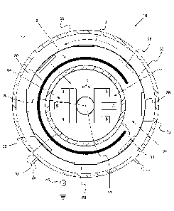
A rotary cathode assembly includes a cathode having a tube shape and defining a hollow center, a shield surrounding the cathode, the shield defining an access opening that exposes a portion of the cathode, and a rotary magnet subassembly disposed within the hollow center of the cathode. The rotary magnet subassembly includes a first magnetic component having a first magnetic field strength and a second magnetic component having a second magnetic field strength. The first magnetic field strength is greater than the second magnetic field strength. Characteristically, the first magnet component and the second magnetic component are rotatable between a first position in which the first magnetic component faces the access opening and a second position in which the second magnetic component faces the access opening. A coating system including the rotary cathode assembly is also provided.


French Abstract

Un assemblage de cathode rotative comprend une cathode de forme cylindrique définissant un centre creux, un blindage entourant la cathode et définissant une ouverture d'accès exposant une partie de la cathode et un sous-assemblage daimant rotatif placé dans le centre creux de la cathode. Le sous-assemblage daimant rotatif comprend un premier élément magnétique présentant une première force de champ magnétique et un deuxième élément magnétique présentant une deuxième force de champ magnétique. La première force de champ magnétique est plus grande que la deuxième. Le premier élément magnétique et le deuxième élément magnétique peuvent tourner entre une première position, dans laquelle le premier élément magnétique est orienté vers louverture d'accès, et une deuxième position, dans laquelle le deuxième élément magnétique est orienté vers louverture daccès. Un système de revêtement comprenant lassemblage de cathode rotative est aussi décrit.

Claims

Note: Claims are shown in the official language in which they were submitted.


WHAT IS CLAIMED IS:
1. A rotary cathode assembly comprising:
a cathode having a tube shape and defining a hollow center;
a shield surrounding the cathode, the shield defining an access opening that
exposes a portion
of the cathode; and
a rotary magnet subassembly disposed within the hollow center of the cathode,
the rotary
magnet subassembly includes a first magnetic component having a first magnetic
field strength for
magnetron sputtering and a second magnetic component having a second magnetic
field strength for
cathodic arc deposition such that the rotary cathode assembly operates in a
magnetic sputtering mode
or a cathodic arc deposition mode, the first magnetic field strength is
greater than the second
magnetic field strength, wherein the first magnetic component and the second
magnetic component
are rotatable between a first position in which the first magnetic component
faces the access opening
and the second magnetic component is shielded by the shield and a second
position in which the
second magnetic component faces the access opening and the first magnetic
component is shielded
by the shield; and
a user operated controller configured to for a user to select the magnetic
sputtering mode or
the cathodic arc deposition mode.
2. The rotary cathode assembly of claim 1 wherein the shield is
electrically floating.
3. The rotary cathode assembly of claim 1 wherein the first magnetic field
strength is from
about 50 to 500 Gauss.
4. The rotary cathode assembly of claim 3 wherein the second magnetic field
strength is from
about 10 to 100 Gauss.
5. The rotary cathode assembly of claim 1 wherein a substrate to be coated
is positioned in front
of the access opening.
6. The rotary cathode assembly of claim 5 wherein the substrate follows a
linear trajectory.
6
Date recue/Date received 2023-05-04

7. The rotary cathode assembly of claim 5 wherein the substrate follows a
circular trajectory or
a planetary three-axis trajectory.
8. The rotary cathode assembly of claim 1 wherein the first magnetic
component and the second
magnetic component are mounted on a support member that is rotated by an
electric motor.
9. The rotary cathode assembly of claim 1 wherein the cathode has a
circular cross section.
10. The rotary cathode assembly of claim 1 wherein the cathode is powered
by a power system,
the power system outputting a first voltage in a first voltage range for
cathodic arc and a first current
in a first current range for cathodic arc deposition, the power system also
outputting a second voltage
in a second voltage range and a second current in a second current range for
magnetron sputtering.
11. The rotary cathode assembly of claim 10 wherein the first voltage range
is from 20 to 40
voltage and the first current range is from 100 to 600 A and wherein the
second voltage range is
from 300 to 1600 volts and the second current range is from 10 to 100 A.
12. A coating system comprising:
a coating chamber; and
a rotary cathode assembly disposed in the coating chamber, the rotary cathode
assembly
including:
a cathode having a tube shape and defining a hollow center;
a shield surrounding the cathode, the shield defining an access opening that
exposes a
portion of the cathode; and
a rotary magnet subassembly disposed within the hollow center of the cathode,
the
rotary magnet subassembly includes a first magnetic component having a first
magnetic field
strength for magnetron sputtering and a second magnetic component having a
second magnetic field
strength for cathodic arc deposition such that the coating system operates in
a magnetic sputtering
mode or a cathodic arc deposition mode, the first magnetic field strength is
greater than the second
magnetic field strength, wherein the first magnetic component and the second
magnetic component
are rotatable between a first position in which the first magnetic component
faces the access opening
and the second magnetic component is shielded by the shield and a second
position in which the
7
Date recue/Date received 2023-05-04

second magnetic component faces the access opening and the first magnetic
component is shielded
by the shield; and
a user operated controller configured for a user to select the magnetic
sputtering mode
or the cathodic arc deposition mode.
13. The coating system of claim 12 wherein the shield is electrically
floating.
14. The coating system of claim 12 wherein the first magnetic field
strength is from about 50 to
500 Gauss.
15. The coating system of claim 14 wherein the second magnetic field
strength is from about 10
to 100 Gauss.
16. The coating system of claim 12 wherein a substrate to be coated is
positioned in front of the
access opening.
17. The coating system of claim 16 wherein the substrate follows a linear
trajectory.
18. The coating system of claim 16 wherein the substrate follows a circular
trajectory.
19. The coating system of claim 12 wherein the first magnetic component and
the second
magnetic component are mounted on a support member that is rotated by an
electric motor or a
pneumatic actuator on a lever.
20. The rotary cathode assembly of claim 12 wherein the cathode is powered
by a power system,
the power system outputting a first voltage in a first voltage range for
cathodic arc and a first current
in a first current range for cathodic arc deposition, the power system also
outputting a second voltage
in a second voltage range and a second current in a second current range for
magnetron sputtering.
21. The rotary cathode assembly of claim 20 wherein the first voltage range
is from 20 to 40
voltage and the first current range is from 100 to 600 A and wherein the
second voltage range is
from 300 to 1600 volts and the second current range is from 10 to 100 A.
8
Date recue/Date received 2023-05-04

22. The rotary cathode assembly of claim 1 configured such that substrates
pass in front of the
access opening to provide a line-of-sight path from a portion of a surface of
the cathode to substrates
during coating deposition.
23. The rotary cathode assembly of claim 12 configured such that substrates
pass in front of the
access opening to provide a line-of-sight path from a portion of a surface of
the cathode to substrates
during coating deposition.
9
Date recue/Date received 2023-05-04

Description

Note: Descriptions are shown in the official language in which they were submitted.


CONVERTIBLE MAGNETICS FOR ROTARY CATHODE
TECHNICAL FIELD
10001] In at least one aspect, a cathode assembly that can be used for
both cathodic arc coating
and magnetron sputtering coating systems is provided.
BACKGROUND
[0002] Vacuum coating systems such as magnetron sputtering systems, arc
deposition
systems, chemical vapor deposition systems, and the like are sold as separate
systems. Such coating
systems are expensive and are frequently under-utilized.
[0003] Accordingly, there is a need to provide a novel design to expand
the applications of
coating systems so as to minimize associated costs.
SUMMARY
[0004] In at least one aspect, a rotary cathode assembly is provided. The
rotary cathode
assembly includes a cathode having a tube shape and defining a hollow center,
a shield surrounding
the cathode, the shield defining an access opening that exposes a portion of
the cathode, and a rotary
magnet subassembly disposed within the hollow center of the cathode. The
rotary magnet
subassembly includes a first magnet component having a first magnetic field
strength and a second
magnetic component having a second magnetic field strength. The first magnetic
field strength is
greater than the second magnetic field strength. Characteristically, the first
magnet component and
the second magnetic component are rotatable between a first position in which
the first magnetic
component faces the access opening and a second position in which the second
magnetic component
faces the access opening.
[0005] In another aspect, a coating system that can operate in a
magnetron sputtering mode or
in a cathodic arc deposition mode is provided. The coating system includes a
coating chamber and
the rotary cathode assembly set forth herein.
1
Date Recue/Date Received 2021-03-10

BRIEF DESCRIPTION OF THE DRAWINGS
[0006] For a further understanding of the nature, objects, and advantages
of the present
disclosure, reference should be had to the following detailed description,
read in conjunction with the
following drawings, wherein like reference numerals denote like elements and
wherein:
[0007] FIGURE lA is a cross sectional view of a circular coating system
that includes a rotary
cathode assembly that can be used for cathodic arc coating and sputter
coating.
[0008] FIGURE 1B is a cross sectional view of a rectangular coating
system that includes a
rotary cathode assembly that can be used for cathodic arc coating and sputter
coating.
[0009] FIGURE 1C is a cross sectional view of a coating system
perpendicular to the view of
Figure lA that includes a rotary cathode assembly that can be used for
cathodic arc coating and sputter
coating.
[0010] FIGURE 2 is a cross sectional view showing repositioning of the
rotary cathode
assembly in the coating systems of Figures lA and 1B.
DETAILED DESCRIPTION
[0011] Reference will now be made in detail to presently preferred
embodiments and methods
of the present invention, which constitute the best modes of practicing the
invention presently known
to the inventors. The Figures are not necessarily to scale. However, it is to
be understood that the
disclosed embodiments are merely exemplary of the invention that may be
embodied in various and
alternative forms. Therefore, specific details disclosed herein are not to be
interpreted as limiting, but
merely as a representative basis for any aspect of the invention and/or as a
representative basis for
teaching one skilled in the art to variously employ the present invention.
[0012] It is also to be understood that this invention is not limited to
the specific embodiments
and methods described below, as specific components and/or conditions may, of
course, vary.
Furthermore, the terminology used herein is used only for the purpose of
describing particular
embodiments of the present invention and is not intended to be limiting in any
way.
[0013] It must also be noted that, as used in the specification and the
appended claims, the
singular form "a," "an," and "the" comprise plural referents unless the
context clearly indicates
2
Date Recue/Date Received 2021-03-10

otherwise. For example, reference to a component in the singular is intended
to comprise a plurality
of components.
[0014] The term "comprising" is synonymous with "including," "having,"
"containing," or
"characterized by." These terms are inclusive and open-ended and do not
exclude additional, unrecited
elements or method steps.
[0015] The phrase "consisting of' excludes any element, step, or
ingredient not specified in
the claim. When this phrase appears in a clause of the body of a claim, rather
than immediately
following the preamble, it limits only the element set forth in that clause;
other elements are not
excluded from the claim as a whole.
[0016] The phrase "consisting essentially of" limits the scope of a claim
to the specified
materials or steps, plus those that do not materially affect the basic and
novel characteristic(s) of the
claimed subject matter.
[0017] With respect to the terms "comprising," "consisting of," and
"consisting essentially
of," where one of these three terms is used herein, the presently disclosed
and claimed subject matter
can include the use of either of the other two terms.
[0018] It should also be appreciated that integer ranges explicitly
include all intervening
integers. For example, the integer range 1-10 explicitly includes 1, 2, 3, 4,
5, 6, 7, 8, 9, and 10.
Similarly, the range 1 to 100 includes 1, 2, 3, 4. . . . 97, 98, 99, 100.
Similarly, when any range is called
for, intervening numbers that are increments of the difference between the
upper limit and the lower
limit divided by 10 can be taken as alternative upper or lower limits. For
example, if the range is 1.1.
to 2.1 the following numbers 1.2, 1.3, 1.4, 1.5, 1.6, 1.7, 1.8, 1.9, and 2.0
can be selected as lower or
upper limits.
[0019] For any device described herein, linear dimensions and angles can
be constructed with
plus or minus 50 percent of the values indicated rounded to or truncated to
two significant figures of
the value provided in the examples. In a refinement, linear dimensions and
angles can be constructed
with plus or minus 30 percent of the values indicated rounded to or truncated
to two significant figures
of the value provided in the examples. In another refinement, linear
dimensions and angles can be
constructed with plus or minus 10 percent of the values indicated rounded to
or truncated to two
significant figures of the value provided in the examples.
3
Date Recue/Date Received 2021-03-10

[0020] Throughout this application, where publications are referenced,
the disclosures of these
publications in their entireties are hereby incorporated by reference into
this application to more fully
describe the state of the art to which this invention pertains.
[0021] With reference to Figures lA and 1B, schematic illustrations of a
coating system that
can be used for sputter coating and cathodic arc deposition coatings are
provided. Coating system 10
that includes a rotary cathode assembly 12 that can be used for cathodic arc
coating and sputter coating.
Rotary cathode assembly 12 includes rotary magnet subassembly 14 and cathode
16. Cathode 16 has
a tubular shape and is centered about central axis ai. Typically, cathode 16
has a circular cross-section.
Shield 20 is disposed around rotary cathode assembly 12. In a refinement,
shield 20 is an electrically
floating shield. Shield 20 defines an access opening 24. The cathode assembly
12 is mounted in
coating chamber 26. Although the present invention is not limited by the type
of coating chamber,
Figure lA depicts a chamber with a circular cross-section and Figure 1B
depicts a chamber with a
rectangular cross-section. During operation substrates 28 pass in front of
access opening 24 to provide
a line-of-sight path from a portion of a surface of cathode 16 to the
substrates during coating
deposition. Substrate carrier 30 moves the substrates as indicated along
direction d1. In Figure lA
direction dl is a circular trajectory while in Figure 1B direction d1 is a
linear trajectory. In another
variation, the trajectory can also be or a planetary three-axis trajectory.
Arc striker 31 is also depicted
in Figures lA and 1B. Although the present invention is not limited by the
dimensions of the coating
chamber and components therein, cathode 16 typically has a diameter of at
least 100 mm and typically
less than about 1 m. Coating chamber 26 will have dimensions sufficient to
accommodate the cathode
and additional structure. Therefore, coating chamber can have a width (or
diameter) of at least 200
mm. Typically, heights for coating chamber 26 are from 0.5 to 3 meters.
[0022] Still referring to Figures lA and 1B, rotary magnet subassembly 14
includes a first
magnetic component 32 having a first magnetic field strength and a second
magnetic component 34
having a second magnetic field strength. Characteristically, the first
magnetic field strength is greater
than the second magnetic field strength. The higher magnetic field strength of
first magnetic
component 32 is suitable for magnetron sputtering while the lower magnetic
field strength is more
suitable for cathodic arc deposition. In a refinement, the magnetic field
strength of the first magnetic
component 32 is from about 50 to 500 Gauss while the magnetic field strength
of the second magnetic
component 22 is from about 10 to 100 Gauss.
4
Date Recue/Date Received 2021-03-10

[0023] With reference to Figures 1A, 1B, 1C, and 2, rotation of rotary
magnet subassembly 14
is schematically illustrated. The first magnetic component and the second
magnetic component are
rotatable along direction dr between a first position Pi in which the first
magnetic component 32 faces
the access opening 24 and a second position P2 in which the second magnetic
component 34 faces the
access opening 24. First magnetic component 32 and second magnetic component
34 can be mounted
on a rotatable support member 38 which is rotated by electric motor 40. In a
variation, first magnetic
component 32 and second magnetic component 34 can be mounted on a rotatable
support member 38
which is rotated by a pneumatic actuator on a lever. In a refinement, a user
operates a controller such
that substrates 28 to be coated move in front of access opening 24 (i.e., the
substrates are positioned
in front of the access opening while being coated). A user operates controller
42 to position the first
magnetic component 32 and the first magnetic component 34 for magnetron
sputtering or cathodic arc
deposition as required.
[0024] Figures lA and 1B also depict power system 46 that power cathode
14 providing DC,
Pulsed-DC and RF power thereto, gas port 48 for introducing gas as needed, and
vacuum port 50. In
a refinement, the power system outputs a first voltage in a first voltage
range for cathodic arc and a
first current in a first current range for cathodic arc deposition. In a
further refinement, the power
system also outputs a second voltage in a second voltage range and a second
current in a second current
range for magnetron sputtering. In still a further refinement, the first
voltage range is from 20 to 40
voltage and the first current range is from 100 to 600 A and the second
voltage range is from 300 to
1600 volts and the second current range is from 10 to 100 A. Typically, for
magnetron sputtering and
cathodic arc deposition the pressure is from about 1 mTorr to about 200 mTorr.
[0025] While exemplary embodiments are described above, it is not
intended that these
embodiments describe all possible forms of the invention. Rather, the words
used in the specification
are words of description rather than limitation, and it is understood that
various changes may be made
without departing from the spirit and scope of the invention. Additionally,
the features of various
implementing embodiments may be combined to form further embodiments of the
invention.
Date Recue/Date Received 2021-03-10

Representative Drawing
A single figure which represents the drawing illustrating the invention.
Administrative Status

2024-08-01:As part of the Next Generation Patents (NGP) transition, the Canadian Patents Database (CPD) now contains a more detailed Event History, which replicates the Event Log of our new back-office solution.

Please note that "Inactive:" events refers to events no longer in use in our new back-office solution.

For a clearer understanding of the status of the application/patent presented on this page, the site Disclaimer , as well as the definitions for Patent , Event History , Maintenance Fee  and Payment History  should be consulted.

Event History

Description Date
Inactive: Grant downloaded 2023-10-04
Letter Sent 2023-09-26
Grant by Issuance 2023-09-26
Inactive: Cover page published 2023-09-25
Pre-grant 2023-08-16
Inactive: Final fee received 2023-08-16
Letter Sent 2023-06-19
Notice of Allowance is Issued 2023-06-19
Inactive: Q2 passed 2023-06-16
Inactive: Approved for allowance (AFA) 2023-06-16
Letter Sent 2023-06-02
Request for Examination Received 2023-05-04
Advanced Examination Requested - PPH 2023-05-04
Advanced Examination Determined Compliant - PPH 2023-05-04
Amendment Received - Voluntary Amendment 2023-05-04
Change of Address or Method of Correspondence Request Received 2023-05-04
All Requirements for Examination Determined Compliant 2023-05-04
Request for Examination Requirements Determined Compliant 2023-05-04
Common Representative Appointed 2021-11-13
Application Published (Open to Public Inspection) 2021-09-16
Inactive: Cover page published 2021-09-15
Priority Document Response/Outstanding Document Received 2021-07-13
Inactive: IPC assigned 2021-03-30
Inactive: First IPC assigned 2021-03-30
Inactive: IPC assigned 2021-03-30
Filing Requirements Determined Compliant 2021-03-30
Letter sent 2021-03-30
Inactive: IPC assigned 2021-03-29
Letter Sent 2021-03-26
Priority Claim Requirements Determined Compliant 2021-03-26
Request for Priority Received 2021-03-26
Inactive: QC images - Scanning 2021-03-10
Application Received - Regular National 2021-03-10
Common Representative Appointed 2021-03-10
Inactive: Pre-classification 2021-03-10

Abandonment History

There is no abandonment history.

Maintenance Fee

The last payment was received on 2022-12-16

Note : If the full payment has not been received on or before the date indicated, a further fee may be required which may be one of the following

  • the reinstatement fee;
  • the late payment fee; or
  • additional fee to reverse deemed expiry.

Patent fees are adjusted on the 1st of January every year. The amounts above are the current amounts if received by December 31 of the current year.
Please refer to the CIPO Patent Fees web page to see all current fee amounts.

Fee History

Fee Type Anniversary Year Due Date Paid Date
Application fee - standard 2021-03-10 2021-03-10
Registration of a document 2021-03-10 2021-03-10
MF (application, 2nd anniv.) - standard 02 2023-03-10 2022-12-16
Excess claims (at RE) - standard 2025-03-10 2023-05-04
Request for examination - standard 2025-03-10 2023-05-04
Final fee - standard 2021-03-10 2023-08-16
MF (patent, 3rd anniv.) - standard 2024-03-11 2023-11-07
Owners on Record

Note: Records showing the ownership history in alphabetical order.

Current Owners on Record
VAPOR TECHNOLOGIES, INC.
Past Owners on Record
STERLING WALKER, III MYERS
ZACHARY ZEMBOWER
Past Owners that do not appear in the "Owners on Record" listing will appear in other documentation within the application.
Documents

To view selected files, please enter reCAPTCHA code :


To view images, click a link in the Document Description column (Temporarily unavailable). To download the documents, select one or more checkboxes in the first column and then click the "Download Selected in PDF format (Zip Archive)" or the "Download Selected as Single PDF" button.

List of published and non-published patent-specific documents on the CPD .

If you have any difficulty accessing content, you can call the Client Service Centre at 1-866-997-1936 or send them an e-mail at CIPO Client Service Centre.

({010=All Documents, 020=As Filed, 030=As Open to Public Inspection, 040=At Issuance, 050=Examination, 060=Incoming Correspondence, 070=Miscellaneous, 080=Outgoing Correspondence, 090=Payment})


Document
Description 
Date
(yyyy-mm-dd) 
Number of pages   Size of Image (KB) 
Representative drawing 2023-09-19 1 16
Description 2021-03-09 5 274
Abstract 2021-03-09 1 23
Claims 2021-03-09 3 114
Drawings 2021-03-09 4 131
Representative drawing 2021-09-12 1 16
Claims 2023-05-03 4 201
Courtesy - Certificate of registration (related document(s)) 2021-03-25 1 357
Courtesy - Filing certificate 2021-03-29 1 569
Commissioner's Notice - Application Found Allowable 2023-06-18 1 579
Courtesy - Acknowledgement of Request for Examination 2023-06-01 1 422
Final fee 2023-08-15 3 65
Electronic Grant Certificate 2023-09-25 1 2,527
New application 2021-03-09 9 325
Priority document 2021-07-12 4 137
Change to the Method of Correspondence 2023-05-03 3 73
PPH request / Request for examination / Amendment 2023-05-03 11 579
PPH supporting documents 2023-05-03 2 308