Note: Descriptions are shown in the official language in which they were submitted.
P10334CA00
1
TRANSPORT COORDINATION SYSTEM
FIELD OF INVENTION
The present application relates to transport coordination.
BACKGROUND
Arranging transport by a computer-implemented application for traditional taxi-
type manners of ride-sharing is well known. Examples of such applications
include the Uber and Lyft systems. Such arrangement of transport, by a
computer-
implemented application, does not provide solutions for peer-to-peer ride-
sharing
or transport coordination. Peer-to-peer ride-sharing or transport coordination
relies on traditional arrangements, such as a journey requestor having to
specifically call a peer to ask for transport to a location_ Such traditional
approaches lack efficiency in coordinating transport.
There is a need for improved transport coordination in a peer-to-peer ride-
sharing.
An object of the invention is to address this need, amongst others.
SUMMARY OF INVENTION
According to an aspect of the present invention there is provided a computer-
implemented method of connecting user equipments (UEs) to coordinate a
transport request, the method comprising: receiving at a server, a message
from
a first user equipment, UE, comprising a first user identification, ID, a
destination
and a specified future time; sending, from the server, a message to a
plurality of
second UEs comprising the first user ID, the destination and the specified
future
time; receiving, at the server, a response from a subset of the plurality of
second
UEs indicating an acceptance; receiving or determining, at the server, at
least one
pick up location; determining, at the server, a set of second UEs
corresponding to
a set of proposed riders from the subset of the plurality of second UEs;
sending,
from the server, a trip confirmation message to the set of second UEs
Date Recue/Date Received 2021-03-10
P10334CA00
2
corresponding to the set of proposed riders; calculating, at the server, a
route from
a driver starting location to the destination by way of the at least one pick
up
location; and sending, from the server, the calculated route to the first UE.
In this way, a transportation request can be successfully facilitated between
a
driver and a number of riders. This method can be administered in a highly
efficient manner at the server, managing communications between the driver and
a potentially large number of second UEs. This technique has found great
utility
in identifying otherwise unknown shared interests between groups interested in
travelling to the same location, thereby reducing traffic on the roads and
offering
the potential to reduce the environmental impact of travel.
The UEs are generally cellular telephones and the messages are preferably sent
from the UEs to the server and from the server to the UEs via an app. Messages
can be sent via telecommunication networks or via the internet, as
appropriate.
The method may comprise sending, from the server, the calculated route to the
set of second UEs corresponding to the set of proposed riders. In this way,
the
second UEs can review the calculated route, and can monitor the positions of
all
travellers in real-time.
The message received at the server from the first UE preferably includes a
number
of available seats. The message from the first UE also preferably includes a
trip
title, and may include a graphic or image that is associated with the trip. If
the first
UE does not specify a number of available seats then the server may use a
default
number, such as four, or a different number depending on the stored settings
relating to a vehicle associated with the first UE.
The pick up location may be received at the server from the first UE. in this
way,
the first UE can propose a (single) pick up location at which all of the
riders will
gather. The proposed pick up location may be mandatory or optional, depending
on system settings.
Date Recue/Date Received 2021-03-10
P10334CA00
3
A plurality of pick up locations may be received from the set of second UEs
corresponding to the set of proposed riders. In this way, the riders can each
propose a pick up location, which may correspond to their home address. The
driver can then collect each of the riders. The pick up locations may be a
negotiable parameter between riders and drivers to ensure efficient routing.
One or more pick up locations may also determined at the server based on
stored
parameters related to the first UE and the set of second UEs corresponding to
the
set of proposed riders. In this way, the server can determine one or more pick
up
locations that are mutually most convenient for the driver and the riders.
This can
improve efficiency by avoiding the need for potentially tortuous negotiations
between individuals.
The method may involve receiving, at the server, a selection of the plurality
of
second UEs that are to be sent the message comprising the first user ID, the
destination and the specified future time. The first UE can therefore identify
the
plurality of second UEs with whom they would prefer to travel. The invitation
can
be sent first to these second UEs, and subsequently to other second UEs,
depending on whether the initial invitations are accepted. The method may
involve sending, from the server, a list of available second UEs to the first
UE for
the first UE to make a selection.
The method may comprise filtering the list of available second UEs based on
one
or more parameters determined by the first UE. In one arrangement the first UE
can specify preferred filters to be applied to second UEs, before they select
their
preferred travel companions. The filter may be pre-set, or it may be specified
by
the first UE in a message to the server. in one example, the filter may
specify
preferred locations, a preferred gender and/or a preferred age range,
although, of
course, a variety of other similar filters would be possible. This can allow
the first
UE better flexibility in terms of their choices, and can decrease the risks
inherent
in shared travel.
Date Recue/Date Received 2021-03-10
P10334CA00
4
In some circumstances the method may involve receiving, at the server, a
response from a second UE of the plurality of second UEs indicating a refusal,
and subsequently sending, from the server, a message to at least one further
second UEs comprising the first user ID, the destination and the specified
future
time. This can allow the invitation to be extended to an additional second UE,
in
the event that the initial invitation is refused by an original invitees. This
can allow
the first UE to re-issue invitations to further second UEs to ensure that the
available seats are allocated in time for the trip.
The method may involve sending, from the server, before the trip confirmation
message is sent, a message to the first UE confirming the set of proposed
riders
from the subset of the plurality of second UEs, and receiving, at the server,
a
message from the first UE rejecting at least one of the proposed riders. In
this
way, the transport can be coordinated more quickly and more efficiently in the
case
where the driver does not accept a proposed rider. In some examples, this may
occur because the proposed rider suggests an inconvenient pickup location.
The method may also involve sending, from the server, the position of the
first UE
to the set of second UEs corresponding to the set of proposed riders, and
sending,
from the server, to the first UE the positions of the second UEs in the set of
second
UEs corresponding to the set of proposed riders. This can allow each
participating
UE to display a map showing the location of the first UE and all of the
relevant
second UEs. Each participant in the trip can therefore be appraised of the
real-
time location of every other participant so that they can monitor progress.
This
can help allow participants to adjust where there are differences between
their
actual positions and pick up locations.
The method may also involve determining, at the server, the expected times at
which the first UE is due to arrive at each pick up location. These expected
times
can then be sent from the server to the first UE and the relevant second UEs
and
displayed on their user interfaces.
Date Recue/Date Received 2021-03-10
P10334CA00
The method may also comprise accessing, at the first UE, a telephone number of
a contact stored in a contact list at the first UE; hashing, at the first UE,
the
telephone number of the contact to create a hashed contact telephone number;
and sending, by the first UE, the hashed contact telephone number to the
server.
5 In this way the telephone information of users can be securely stored at
the server.
The server preferably stores a plurality of user profiles, each user profile
comprising a hashed user telephone number corresponding to a UE associated
with the user profile. The server can therefore match hashed contact numbers
to
determine users who are connected with one another, while maintaining
confidentiality with respect to telephone numbers.
According to another aspect of the invention there is provided a server
computer
comprising one or more processors configured to: receive a message from a
first
user equipment, UE, comprising a first user identification, ID, a destination
and a
specified future time; identify a plurality of second UEs which are associated
with
the first UE; send a message to the plurality of second UEs comprising the
first
user ID, the destination and the specified future time; receive a response
from a
subset of the plurality of second UEs indicating an acceptance; receive or
determine, at the server, at least one pick up location; determine a set of
second
UEs corresponding to a set of proposed riders from the subset of the plurality
of
second UEs; send a trip confirmation message to the set of second UEs
corresponding to the set of proposed riders; calculate a route from a driver
starting
location to the destination by way of the at least one pick up location; and
send
the calculated route to the first UE.
According to yet another aspect of the invention there is provided a non-
transitory
computer readable medium comprising executable instructions which, when
executed by a server, cause the server to carry out steps comprising:
receiving at
a server, a message from a first user equipment, UE, comprising a first user
identification, ID, a destination and a specified future time; sending, from
the
Date Recue/Date Received 2021-03-10
P10334CA00
6
server, a message to a plurality of second UEs comprising the first user ID,
the
destination and the specified future time; receiving, at the server, a
response from
a subset of the plurality of second UEs indicating an acceptance; receiving or
determining, at the server, at least one pick up location; determining, at the
server,
a set of second UEs corresponding to a set of proposed riders from the subset
of
the plurality of second UEs; sending, from the server, a trip confirmation
message
to the set of second UEs corresponding to the set of proposed riders;
calculating,
at the server, a route from a driver starting location to the destination by
way of
the at least one pick up location; and sending, from the server, the
calculated route
to the first UE.
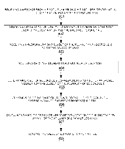
BRIEF DESCRIPTION OF THE DRAWINGS
Embodiments of the invention are now described, by way of example, with
reference to the drawings in which:
Figure 1 is a flow diagram of the operational steps involved in registering a
user
of the transport coordination system;
Figure 2 is a block diagram of a user profile of the transport coordination
system;
Figure 3 is a flow diagram of the operational steps involved in creating a
group
within the transport coordination system;
Figure 4 is a block diagram of a group profile of the transport coordination
system;
Figure 5 is a flow diagram of a first example of the operational steps of
interactions
between entities in the transport coordination system;
Figure 6 is a flow diagram of a second example the operational steps of
interactions between entities in the transport coordination system;
Figure 7 is a block diagram of architecture of the transport coordination
system;
and
Date Recue/Date Received 2021-03-10
P10334CA00
7
Figure 8 is a flow diagram of a process for connecting UEs to coordinate a
transport request.
DETAILED DESCRIPTION
A transport coordination, or ride-sharing, system and method are provided in
which a user of a transport coordination or ride-sharing application loaded on
a
first device can schedule a journey to a destination and invite a second user
of the
ride sharing application loaded on a second device. The second user can accept
the invitation to participate in the scheduled journey. The user of the first
device
can be considered a 'driver', and the user of the second device can be
considered
a 'passenger'.
Figure 1 shows a flow diagram of the operational steps involved in registering
a
user of the transport coordination system. In examples, this can occur before
coordinating transport as subsequently described with reference to Figures 5
and
6.
A user installs the transport coordination application on a device or UE (user
equipment), such as a smartphone device. At step S101, when the user opens
the application for the first time they are presented with a registration
interface. in
an example the registration interface requests the user to enter personal
information such as a telephone number and name. In some examples other
personal information, such as contact information including home and/or work
address, username, payment information and any other suitable information may
also be entered at this stage. In other examples it may be entered later. In
some
examples, a user may register and login using a connected third party
application,
particularly a social application, such as SnapChat. In addition to
registering as a
requestor or passenger, a user can also register as a driver. When registering
as
a driver, the user may be prompted to enter a vehicle registration number,
and/or
scan a copy of their driver's license which is then verified. A user profile
of a user
who can act as a driver can include an attribute indicating that the user is a
driver.
Date Recue/Date Received 2021-03-10
P10334CA00
8
The application also asks for device permissions to receive push
notifications. At
step 5102 the user enters the requisite personal information. The application
also
requests access to the address book of the UE, which the user can grant.
At step 5103, the application hashes the user's telephone number (i.e. the
telephone number of the UE). At step S104, the application also hashes the
contact telephone numbers of the user's contacts from the address book. In an
example the application uses MD5 hashing, although any other suitable type of
hashing may instead be used. The application can store the hashed contact
telephone numbers in a hash table at the UE. In some examples, other
information such as a username may be hashed and stored in the hash table. At
step S105, the application sends the hashed user telephone number, as well as
the other personal information, to a server that hosts the transport
coordination
system. The application also sends the hashed contact telephone numbers and
home address, if a home address has been provided, to the server,
At step 5106, the server receives the user's personal information, the hashed
user
telephone number, the hashed home address, and hashed contact telephone
numbers, and stores this information in a user profile of the user at the
server.
Figure 2 shows an exemplary block diagram of a user profile 200 stored at the
server, including the user's name information 202, the plain and the hashed
user
telephone number 204, the hashed contact telephone numbers 206, payment
information 208, the user's connections 210 to other users of the transport
coordination system, a user profile identifier 212 such as a unique reference
number associated with the user profile, a UE identifier 214 of the UE
associated
with the user profile 200 and the user's group membership information 216. In
some examples, the payment information is tokenized and the server stores
tokens issued by a partner payment service provider; payments can then be
requested with these tokens. The user profile can also include a driver
attribute
for users who are verified as drivers within the system. User profiles with
the
driver attribute can be considered as 'driver profiles'. In some examples,
only
users with the driver attribute can act as drivers, whereas all users can act
as
Date Recue/Date Received 2021-03-10
P10334CA00
9
passengers. The skilled person will readily understand that any other suitable
user information can be stored in the user profile 200.
At step S107, the server matches the hashed contact telephone numbers with
matching hashed user telephone numbers of other user profiles registered with
the transport coordination service. That is, contacts of the user who are
already
registered with the transport coordination service, and whose respective
hashed
user telephone numbers are already stored at the server in their own
respective
profiles, are matched with the user by way of the matching hashed contact
telephone numbers.
At step S108, the server connects the user's profile with the profiles of the
other
users with a hashed user telephone number matching one of the user's hashed
contact telephone numbers 206, thereby establishing a connection between the
users of the transport coordination system such that the users are connections
within the system. These connections can be considered first-level
connections.
Any unidentified hashed contact telephone numbers, that is hashed contact
telephone numbers that do not match a hashed user telephone number in an
existing user profile, are stored at the server in a 'waiting list' associated
with the
user profile. In this way, when a new user joins the system, the new user's
hashed
user telephone number may be matched against the hashed contact telephone
number in the existing user's 'waiting list'. In this way the new user and the
existing user can be associated as connections in the system. The hashed
contact telephone number is then deleted from the 'waiting list'.
At step 5109, the server may determine the respective first-level connections
of
each of the first-level connections associated with the user's profile and
connect
these to the user's profile as second-level connections.
In some examples, the application may detect a change to the user's address
book at the UE. For example, the user may have added a new contact to their
address book. When this occurs the application hashes this new contact
Date Recue/Date Received 2021-03-10
P10334CA00
telephone number and sends it to the server where it is stored in the users
profile
as a hashed contact telephone number. If this hashed contact telephone number
matches an existing hashed user telephone number of another user profile
stored
at the server, a connection is established between the users such that the
users
5 are connections within the system. In this way, if the user adds a new
contact to
the address book of the UE and the new contact is also a user of the transport
coordination system, the user and the new contact become connections within
the
transport coordination system. Within the application, a list of friends (i.e.
the
user's connections within the system) is pulled from the server, this allows
the
10 friend list to be refreshed each time the user accesses the friend list
within the
application.
In some examples, users of the transport coordination system can create, join
and
administrate 'groups' of user profiles via interfaces of the transport
coordination
application loaded onto their UEs. Figure 3 shows a flow diagram of the
operational steps involved in creating a group. Each group created in the
transport
coordination system may be stored in the server as a group profile 400. Figure
4
shows an exemplary block diagram of a group profile 400 stored at the server,
including: the group's information 402; a unique group identifier, group ID
404: a
list of the user profile identifiers of the group's administrators, group
admins 406;
a list of the user profile identifiers of members of the group, group members
408;
and privacy and admission settings 410.
At step S301, the user navigates to a group creation interface of the
transport
coordination application loaded onto the UE which prompts the user to enter a
group name. In some examples, the user may be prompted to enter optional
information such as a profile image, a description of the group, or a
geographical
area associated with the group.
The user who creates the group may be considered the 'group administrator'. in
some examples, group administrators have additional group privileges which may
allow them to edit group information, accept or decline users who have
requested
Date Recue/Date Received 2021-03-10
P10334CA00
11
to join the group, assign a public or private setting to the group, or assign
an
admission policy for the group.
At step S302, the group administrator may select other users to invite to the
group
from a list of their first and second level connections. In some examples, the
user
may be able to select an option on an interface of the UE to invite other
users to
the group as additional group administrators or as members which do not have
administrator privileges.
At step S303, the group administrator is prompted to select a privacy setting
and
an admission policy for the group via an interface of the application. The
group
administrator can select a private setting, in which the group is not shown to
all
users of the transport coordination application through a group browsing
interface.
Alternatively, the group administrator can select a public setting, in which
all users
of the transport coordination application can view the group information of
the
public group and send a request to join the group via the group browsing
interface.
Additionally, the group administrator may select a closed admission policy in
which
a group administrator is required to accept a user request to join a group
before
the requesting user can join the group. Alternatively, the group administrator
may
select an open admission policy, in which an administrator is not required to
accept
user requests to join the group. In this latter case, a request sent by a user
to join
a group automatically adds the user to the group. In some examples, a public
or
private group setting may not be implemented. In which case, groups may be
joined only by way of invitation from a group member or group administrator.
At step S304, the application sends the group name and any additional
information
provided by the group administrator, a list of users to be invited to the
group, and
the selected privacy and admission settings for the group to the server that
hosts
the transport coordination system.
At step S305, the server receives the information sent by the application in
step
S304. The server then creates a group profile 400 for the group and stores the
Date Recue/Date Received 2021-03-10
P10334CA00
12
group information 402 such as the group name and description, the user
identifier
of the group administrator, and the privacy and admission settings 410 in the
group
profile 400. At step S306 the group is assigned a unique group identification
number 404 which is stored in the group profile 400. The group identification
number 404 is also stored in the user profile 200 associated with the group
administrator. The group identification number 404 may also be stored in the
user
profile 200 of each member of the group. A list of group administrators of the
group is maintained at the server in the group profile 400. This list is
updated
whenever the server receives a message indicating that a new user has accepted
an invitation to join the group as an administrator. Similarly, the user
profiles of
the new group administrators are updated to record which groups they are
administrators of.
At step S307 the server sends an invite message to a plurality of UEs
associated
with the users selected by the group administrator to be invited to the group.
The
server may determine which UEs correspond to the users selected by the group
administrator by matching the user profile identifiers selected by the group
administrators to the corresponding UE identifier. The users associated with
the
plurality of UEs can accept the invite message through an interface of the
application loaded onto the UE. The UEs can then send a response message to
the server which comprises an acceptance indicator, indicating acceptance of
the
invitation. The UE identifier 214 and the user profile identifier 212
associated with
each user who accepts the invitation are added to the group members 408 of the
group profile 400. Alternatively or additionally, they are also added to the
group
administrators 406 of the group profile 400 if that user has been invited to
join the
group as an administrator. Alternatively, the users can decline the invitation
to join
the group by selecting a decline option provided on an interface of the UE. In
this
latter case, the user is not added to the list of group members 408 or the
list of
group admins 406 within the group profile 400.
In some examples, if the group administrator has selected a public privacy
setting
for the group, then step S308 occurs at which the group is made visible to all
users
Date Recue/Date Received 2021-03-10
P10334CA00
13
of the transport coordination application via a group browsing interface.
Otherwise, the group is not made visible to all users of the transport
coordination
application. The group browsing interface enables users to browse public group
profiles stored on the server and view the group information with each public
group. Users can then select a group they wish to join, and send a request to
join
the group using the group browsing interface. The request is then forwarded to
the group administrators, via the server, who can accept or decline the
request.
Figure 5 shows a flow diagram of the operational steps of interactions between
entities in the system involved in a first user (Le. the driver) of a first UE
2 in the
transport coordination system scheduling a journey to a destination. The
operational steps are shown between entities of the system when users (i.e.
passengers) of a second UE 4, a third UE 6, a fourth UE 8, a fifth UE 10, a
sixth
UE 12, and a seventh UE 14 in the transport coordination system accept,
decline
or do not respond to an invitation to participate in the journey to the
scheduled
destination. Each of the UEs has the transport coordination application loaded
thereon.
At step S502 the transport coordination application loaded on a first UE 2,
that is
a UE of the driver who wishes to schedule a journey, presents a user interface
on
a display of the first UE 2. The driver can enter a scheduled destination, a
trip
name, a journey date and time which is in the future, whether or not the
journey
should be associated with a group (i.e. the group should be a 'group
journey'), and
a number of available seats. The number of available seats corresponds to the
number of available seats in a vehicle which the driver wishes to provide to
users
(i.e. passengers) of the transport coordination application to participate in
the
journey undertaken with the vehicle. In some examples, a journey can be
scheduled 5 minutes in advance of the journey time, giving the ability for
spontaneous journey planning. The skilled person would understand that other
appropriate minimum time periods may be implemented. In some examples, the
number of available seats may be set to four by default. In some examples,
additional trip information may be provided at this step, such as a trip
description
Date Recue/Date Received 2021-03-10
P10334CA00
14
or an image file. The journey time can be entered as an arrival time or a
departure
time by selecting an 'arrival time' option or a 'departure time' option
presented on
the user interface. The journey time option selected can be later used to
calculate
an optimal route, a leaving time or an arrival time. In the example of Figure
5, the
user does not choose to associate the journey with a group.
At step 3504A the first UE 2 generates and sends a connections list request
message to a server 16, requesting the list of all the user connections 210 of
the
driver. This list can be considered the driver's 'connections list'. Filters
may be
selected by the driver via an interface of the ride sharing application loaded
onto
the first UE 2, and included in the connections list request message. Examples
of filters can include a preference for 'favourite' friends, a filter for
connections
above or below a certain age, a filter for only female or male connections, a
filter
for connections only within a certain distance, or a filter for only first or
second
level connections. The skilled person will readily understand that any other
suitable filters can also be used. In an example, the filters may be applied
to show
a number of favourite friends as well as a number of geographically closest
friends. The filters are applied as defined by the user within the
application. One
or more filters may be applied.
At step 3504B the server receives the connections list request message. The
server 16 can determine the filters included in the connections list request
message and apply these selected filters to the user connections 210 in the
driver's profile 200. The connections list can then be generated from the user
connections 210 in the driver's user profile 200 based upon the filters
provided in
the connections list request message.
At step 3506A the server 16 generates the connections list which comprises
user
profile identifiers 212 corresponding to users from the driver's first and
second
level connections in the driver's user profile 200, according to any selected
filters.
The server 16 then sends list to the first UE 2. The first UE 2 receives the
connections list at step 3506B.
Date Recue/Date Received 2021-03-10
P10334CA00
At step S508, the application loaded on the first UE 2 presents the driver
with the
connections list, and the driver selects a number of connections from the
connections list to invite, via an interface of the application. In an
example, the
presented interface may be on a touchscreen interface at which the user of the
5 first UE 2 can select their preferred connections by pressing a name,
image or
other information associated with the connection displayed on the touchscreen.
The selected connections can be considered 'invitees'. In some examples, a
number of invitees may be chosen up to the number of available seats. In the
example of Figure 5, the driver initially selects a second user which is
associated
10 with a second UE 4, a third user which is associated with a third UE 6,
a fourth
user which is associated with a fourth UE 8 and a fifth user which is
associated
with a fifth UE 10. In other examples, the system may be configured to allow
the
driver to select more users to invite than there are available seats. In such
embodiments, the users who first to respond to the invite and are first
accepted
15 by the driver to participate may be allocated an available seat on the
trip.
At step S510, the transport coordination application prompts the driver to
select a
pickup location option for the scheduled journey. The driver can make a
selection
from: 'mandatory pickup location' or 'suggested pickup location'. If the
driver
selects the 'mandatory pickup location' option, then the invitees will not
later be
prompted to provide a pickup location. In such examples, the invitees are
required
to accept the suggested pickup location in order to participate in the
journey. If
the driver selects the 'suggested pickup location' option, then the invitees
will later
be prompted to either accept the suggested pickup location, or reject the
suggested pickup location. if the suggested pickup location is rejected by an
invitee, the invitee can then be prompted to provide a new pickup location. In
the
example of Figure 5, the driver selects the 'suggested pickup location'
option.
At step 8512, the driver provides a suggested pickup location. The pickup
location
may be selected via an interface on the application which comprises a map. The
suggested pickup location may be the driver's home address by default. In some
examples, if the driver has selected the 'suggested pickup location' option,
the
Date Recue/Date Received 2021-03-10
P10334CA00
16
transport coordination application may present the driver with a further
option to
not provide a suggested pickup location. If the driver elects not to provide a
suggested pickup location, the invitees would then later be required to
suggest an
alternative pickup location in order to accept the journey invitation. In such
cases,
the driver may be additionally required to provide a starting location, at
which the
driver intends to begin the journey.
At step S514A, the first UE 2 generates a journey creation message. The
journey
creation message comprises all of the information input by the driver in steps
S502-5512, such as: the scheduled destination; the journey name; the journey
date and time; the list of invitees selected from the driver's connections
list, which
comprises a list of user profile identifiers 212 corresponding to the
invitees; the
selected pickup option; the pickup location, if a pickup location has been
suggested (or demanded); any additional information provided in step S502, and
the user profile identifier 212 of the driver.
The journey creation message may comprise one or more GPS locations
associated with the selected scheduled destination and, in relevant examples,
the
suggested pickup location. Any other suitable location information in place of
GPS
locations can be used. It will be understood that whenever GPS location and
navigation are described throughout the description of all embodiments in the
present disclosure, any other suitable type of location information and
navigation
can be used as alternatives, for example other GNSS systems, regional
navigation
systems, a coordinate system, and cellular location amongst others.
At step S514B, the server 16 receives the journey creation message.
At step 5516, the server 16 determines the UE associated with each of the
connections, or invitees, selected by the driver. This is done by matching the
user
profile identifiers 212 in the journey creation message to the corresponding
UE
identifiers 214 stored at the server 16. In this example, the server 16
identifies
Date Recue/Date Received 2021-03-10
P10334CA00
17
the UEs corresponding to the invitees as the second UE 4, third UE 6, fourth
UE
8, and fifth UE 10.
At step S518A, the server 16 generates and sends a journey invite message to
the second UE 4, the third UE 6, the fourth UE 8 and the fifth UE 10. The
journey
invite message comprises the journey name; the journey date and time; any
additional information provided in step 5502; the selected pickup option; the
pickup location, if a pickup location has been suggested; and the user profile
identifier 212 of the user profile associated with the first UE 2 (i.e. the
user profile
identifier of the driver). In some embodiments, a list of user profile
identifiers 212
of the invitees selected by the driver may also be included in the journey
invite
message which is sent to the second UE 4, third UE 6, fourth UE 8, and fifth
UE
10. The skilled person would understand that other information could be
included
in the journey invite message. At step 5518B the second UE 4, third UE 6,
fourth
UE 8, and fifth UE 10 receive the journey invite message.
At step S520, the applications loaded on the second UE 4, third UE 6, fourth
UE
8, and fifth UE 10, each present the user of the UE with a journey invite
interface
on a display of the UE. The journey invite interface displays the information
received in the journey invite message, such as the scheduled destination, the
user name information 202 of the driver, the journey date and time; the
selected
pickup option; the pickup location, if a pickup location has been suggested;
and
any additional information provided in step 5502. The journey invite interface
of
the application loaded on each UE prompts each user to accept or decline the
invite by selecting an 'accept journey' option, or a 'decline journey' option.
In the
example of Figure 5, if the accept journey option is selected, the journey
invite
interface then prompts the corresponding user to accept or decline the
suggested
pickup location provided by the driver. The application presents an 'accept
pickup
location' option, or a 'decline pickup location' option, which the
corresponding user
can select by, for example, tapping on a touchscreen display of the UE.
Date Recue/Date Received 2021-03-10
P10334CA00
18
In the example of Figure 5, at step S520, the second user selects the 'accept
journey' option and the 'accept pickup location' option. At step S522A, the
second
UE 4 generates a journey invitation response message comprising a journey
acceptance indicator which indicates that the second user has accepted the
journey invitation. The journey response message additionally comprises a
pickup
location acceptance indicator which indicates that the second user accepts the
suggested pickup location. The journey invitation response message is then
sent
to the server 16. At step S522B, the server 16 receives the journey invitation
response message. The server 16 then determines the indicators included in the
message, and keeps a record of the indicators received at the server 16. The
server 16 then forwards the invitation response notification message to the
first
UE 2 which is associated with the driver. At step S522C, the message is
received
at the first UE 2 and a notification is displayed on an interface of the first
UE 2
which indicates to the driver that the second user has accepted the journey
invitation and accepted the suggested pickup location.
The server 16 is to be understood to automatically determine and store the
result
of any indicators included in a message sent to the server 16. in this way,
the
server 16 can record which users have provided journey acceptance indictors,
and can thus determine that those users are 'booked in', or have been
'allocated
an available seat' on the scheduled journey.
In the example of Figure 5, at step S520, the third user selects the 'accept
journey
invite' and the 'decline suggested pickup location' options. At step S524, the
third
UE 6 then presents the third user with a pickup location interface which
allows the
third user to suggest an alternative pickup location. The third user then
enters a
new pickup location using an interface of the application loaded onto the
third UE
6. In some examples, the interface may comprise a map.
At step S526A, the third UE 6 generates a journey invitation response message
comprising a journey acceptance indicator, and a pickup location rejection
indicator which indicates that the third user has rejected the suggested
pickup
Date Recue/Date Received 2021-03-10
P10334CAO0
19
location. The journey invitation response message further comprises the newly
suggested alternative pickup location. The journey response message is then
sent to the server 16 which receives the message at step S52613. At step
S526B,
the server 16 then forwards the journey response message to the first UE 2
which
is associated with the driver. The invitation response message is received at
the
first UE 2 at step S526C.
At step S528, the application loaded on the first UE 2 determines that the
journey
response message sent by the third UE 6 comprises a pickup location rejection
indicator. As a result, the first UE 2 presents the driver with an interface
which
prompts the driver to accept or decline the new pickup location by selecting
an
'accept new pickup location' option, or a 'decline new pickup location'
option. The
interface may display the suggested alternative pickup location on a map. In
the
example of Figure 5, the driver accepts the new pickup location. In other
examples, the driver may reject the new pickup location. In the case where the
driver rejects the new pickup location, the transport coordination system may
generate messages and provide interfaces which allow the driver and the third
user to continually re-suggest new pickup locations until a pickup location is
accepted by both the driver and the third user. In other embodiments,
rejecting
the new pickup location may retract the invite to the third user, and cause
the
server 16 to provide the driver with a connections list so that other
connections of
the driver can be invited to replace the third user.
At step S530A, the first UE 2 generates a pickup location response message
comprising an indicator which indicates that the driver has accepted the
alternative
pickup location. The new pickup location response message is then sent by the
first UE 2 to the server 16. The message is received at the server 16 at step
S530B and forwarded to the third UE 6. At step S530C, the message is received
by the third UE 6. The third UE 6 determines that the message received
comprises
an indicator which indicates that the first user has accepted the alternative
pickup
location. The third UE 6 then generates and displays a notification on an
interface
Date Recue/Date Received 2021-03-10
P10334CA00
of the application loaded onto the third UE 6 which indicates to the third
user that
the driver has accepted the new pickup location.
In the example of Figure 5, at step S520, the fourth user selects the 'decline
journey' option. In response, at step S532A, the fourth UE 8 generates a
journey
5 invitation response message comprising a decline journey indicator which
indicates that the fourth user has declined the journey invite message. The
journey invitation response message is then sent to the server 16. At step
S532B,
the server 16 receives the journey invitation response message. The server 16
then forwards the invitation response notification message to the first UE 2
which
10 is associated with the driver. The server 16 may also add to the journey
invitation
response message the user profile identifiers 212 of the first and second
level
connections of the driver, so that the driver can later pick a new connection
to
invite. At step S532C, the message is received at the first UE 2 and a
notification
is displayed on an interface of the first UE 2 which indicates that the fourth
user
15 has declined the journey invitation.
Step 5534 occurs in response to the first UE 2 determining that the journey
invitation response message received from the third UE 6 comprises a journey
decline indicator. The application loaded onto the first UE 2 presents the
driver
with an interface which allows the driver to select a new connection to invite
to
20 participate in the journey. In the example of Figure 5, the driver
selects a sixth
user corresponding to a sixth UE 12. In other examples, the driver may elect
not
to select a new connection to invite, and undertake the scheduled journey with
an
unfilled seat.
At step S536A, the first UE 2 generates a new invitee message comprising the
user profile identifier 212 associated with the sixth user, and sends the
message
to the server 16. The server 16 receives the new invitee message at step S536B
and generates a journey invite message, as described with reference to step
S518A. The server 16 matches the user profile identifier of the sixth user
selected
by the driver to the UE identifier 214 of the sixth UE 12 and sends the
journey
Date Recue/Date Received 2021-03-10
P10334CA00
21
invite message to the sixth UE 12. The journey invite message is received at
the
sixth UE 12 at step S536C.
At step S538, the application loaded on the sixth UE 12 presents the user of
the
sixth UE with a journey invite interface on a display of the UE, as described
with
reference to step S520. The journey invite interface prompts the sixth user to
accept or decline the invite. In the example of Figure 5, the journey invite
interface
also prompts the user to accept or decline the suggested pickup location
provided
by the driver. In this example, the sixth user selects the 'accept journey'
and the
'accept suggested pickup location' option.
At steps S540A, S540B, and S540C, a journey invitation response message is
generated at the sixth UE 12 and sent to the first UE 2, via the server 16, as
described in reference to steps S522A, S522B, and S522C, respectively. At step
S540C, the message is received at the first UE 2 and a notification is
displayed
on an interface of the first UE 2 which indicates that the sixth user has
accepted
the journey invitation and accepted the suggested pickup location.
In the example of Figure 5, at step S520, the fifth user does not respond to
the
journey invite message. In examples, this may be occur because the fifth UE 10
is switched off, does not have a suitable connection to receive the journey
invite
message, or because the fifth user does not select an option to accept or
decline
the journey invite message.
At step S542A, the driver navigates to an interface of the transport
coordination
application loaded onto the first UE 2 and initiates a reminder. In response,
the
first UE 2 generates a reminder message comprising an indicator that prompts
the
recipient application of the reminder message to provide a reminder to respond
to
the journey invite message. The first UE 2 then sends the reminder message to
the server 16. The reminder message is received at the server 16 at step S542B
and forwarded onto the fifth UE 10. The fifth UE 10 receives the reminder
message at step S542C. In the example of Figure 5, the fifth user still does
not
Date Recue/Date Received 2021-03-10
F10334CA00
22
provide a response to the journey invite message. In some examples, the driver
may be able to send additional reminders to the invitees who have not provided
a
response to the journey invite message. In some examples, reminders may be
issued by the server 16 automatically.
At step 3544A, which occurs at a predetermined time period before the
scheduled
journey time, the server 16 determines the number of unfilled available seats.
This
can be calculated by subtracting the number of journey invitation response
messages comprising invitation acceptance indicators that have been sent
through the server 16 from the number of available seats provided by the
driver in
the journey creation message. The server 16 generates a no response message
comprising an indicator that prompts the recipient application to notify the
driver
that the fifth user has still not responded to the journey invite message. The
server
16 also adds to the no response message the user profile identifiers 212 of
the
first and second level connections of the driver before sending the no
response
message to the first UE 2. At step 3554B, the no response message is received
at the first UE 2 and a notification is displayed on an interface of the first
UE 2 that
indicates that the fifth user has still not responded to the journey
invitation.
Preferably, the predetermined time period before the scheduled journey time at
which step 3544A occurs is 24 hours. The skilled person would understand that
other time periods may be used alternatively or in addition. In some example
embodiments, the transport coordination system may allow the driver to select
the
predetermined time period via a settings interface of the application loaded
onto
the first UE 2.
At step S546, the application loaded on the first UE 2 presents the driver
with an
interface that allows the driver to select a new connection to invite to
participate
in the journey, to replace the unresponsive fifth user. In the example of
Figure 5,
the driver selects a seventh user which is associated with a seventh UE 14. in
other examples, the driver may elect not to select a new connection to invite
and
proceed to complete the journey only with the second user, the third user and
the
Date Recue/Date Received 2021-03-10
P10334CA00
23
sixth user corresponding to the second UE 2, the third UE 8 and the sixth UE
12,
respectively.
In some examples, the driver can send additional journey invitation messages
to
a plurality of users associated respectively with a plurality of UEs, in
addition to
the seventh UE 14, in order to try and ensure that the remaining available
seat is
filled. In such examples, the user of a UE of the plurality of additional UEs
who
first responds to the journey invite message with a journey acceptance
indicator,
and who is first accepted by the driver, may be allocated the remaining
available
seat. For the sake of clarity of the diagrams, the specific operational steps
involved in this process are not shown in Figure 5.
Once the driver selects the seventh user to invite to participate in the
journey,
steps S548A-S552C proceed as described with reference to steps S536A-S540C,
respectively, in which the sixth user receives and accepts a journey invite
message. In summary, steps S548A-S552C proceed as follows: the first UE 2
generates a journey invite message and forwards the message to the seventh UE
14 which is associated with the seventh user, via the server 16. The seventh
user
selects the 'accept journey invite' and the 'accept suggested pickup location'
option via an interface of the application loaded onto the seventh UE 14. The
seventh UE 14 generates and sends, via the server 16, a journey response
message to the first UE 2 comprising an indicator which indicates that the
seventh
user has accepted the journey invitation and the suggested pickup location.
The skilled person would understand steps S520 to S552C may occur in other
orders. In general the order will be determined by the order in which the
first user
(i.e. the driver), the second user, the third user, the fourth user, the fifth
user, the
sixth user and the seventh user respond (or do not respond) to the plurality
of
invitations and messages described so far in this application.
At step S554, the server 16 checks if the number of messages comprising
outstanding journey acceptance indicators sent via the server 16 equals the
Date Recue/Date Received 2021-03-10
P10334CA00
24
number of available seats, as provided in the journey creation message. The
server determines that the number of outstanding journey acceptance indicators
equals the number of available seats. Thus, the server 16 determines the
journey
is 'closed', and that there are no more available seats waiting to be
allocated to a
user. in other examples, this check may occur each time after a message
containing a journey acceptance indicator is received by the server 16 so that
the
server 16 can determine when the journey is closed.
Step S556A occurs in response to the server 16 determining that the journey is
closed, as described in step S554. At step S556A, the server 16 generates a
journey closed message comprising an indicator which indicates that there are
no
more available seats on the trip. The server 16 sends the journey closed
message
to the first UE 2 corresponding to the driver, and to all of the UEs
corresponding
to users which have either accepted the journey invite message or have not
responded to the journey invite message. In the example of Figure 5, the
server
16 sends the journey closed message to the second UE 4, the third UE 6, the
fifth
UE 10, the sixth UE 12, and the seventh UE 14. The UEs receive the journey
closed message at step S556B. The fourth user is not sent a journey closed
message because the fourth user declined the journey invite message at step
S520.
The server 16 can add additional information to the journey closed message
depending on the intended recipient UE. The journey closed message sent to the
driver additionally includes the user profile identifiers 212 of all of the
users
associated with the UEs which provided a journey acceptance indicator to the
server 16. The journey closed message sent to the second UE 4, the third UE 6,
the sixth UE 12 and the seventh UE 14 may additionally comprise an indicator
which prompts the applications loaded on the corresponding UEs to provide a
notification informing the user that they have been booked in on the journey.
The
journey closed message sent to the fifth UE 10 may comprise an indicator which
prompts the application loaded on the fifth UE 10 to indicate via the
interface that
they have not been booked in on the journey because they failed to respond in
Date Recue/Date Received 2021-03-10
P10334CA00
time. In some examples, the users booked in on the journey are also provided
with the user profile identifiers 212 of the other users who are booked in on
the
journey. This can be implemented by the server 16, which can add the
appropriate
user profile identifiers 212 to the appropriate journey closed messages.
5 At step S558, the server 16 calculates the optimal route between the pickup
locations and the destination. In the example of Figure 5, the server 16
calculates
the optimal route that sequentially connects the pickup location initially
suggested
by the driver, the pickup location suggested by the third user, and the
destination.
The server 16 also determines the distance of the optimal route using GPS
10 information of each location. in other examples where the driver
does not suggest
a pickup location, the route may be calculated from a starting location
provided by
the driver to each pickup location, and then subsequently to the destination
location.
Once the server 16 has calculated the optimal route for the journey, the
server 16
15 calculates a first, a second, a third, and a fourth estimated cost
for the journey at
step S559. The first estimated cost can be based on a first unit price per
mile
multiplied by the number of miles the server 16 expects the driver to travel
during
the journey, based on the provided GPS location information. The second
estimated cost can be based on the first estimated cost divided the number of
20 users participating in the journey, including the driver. In an
example, the second
estimated cost may be the price which is charged to each passenger user. The
third estimated cost can be based on a second unit price per mile multiplied
by
the number of miles the server 16 expects the driver to have travel during the
journey, also based on the provided GPS location information. The fourth
25 estimated cost can be based on the third estimated cost divided the
number of
users participating in the journey, including the driver. The fourth estimated
cost
may be the price which is paid to the driver by each passenger user. In such
an
example, the first unit price per mile may be higher than the second unit
price per
mile, thereby making the first estimated cost higher than the third estimated
cost.
In some examples, the estimated costs can later be used to calculate a final
cost.
Date Recue/Date Received 2021-03-10
P10334CA00
26
In other examples, the estimated costs may be used as final costs which are
charged to the passengers and paid to the driver. In some examples, the server
16 sends the estimated costs in a message to each UE participating in the
journey,
so that the UE can display the estimated cost to the user in a notification.
The
estimated costs may be pre-authorised with a payment service provider at this
step, before the journey is scheduled to take place, using payment information
provided by each user during registration. In this way, the payment from each
passenger is assured. In some examples, the passengers may be charged and
the driver may be paid, using the estimated costs, at this step.
The journey time provided by the driver in step S502 can be entered as an
arrival
time or a departure time by selecting an 'arrival time' option or a 'departure
time'
option, provided at step S502. The driver can select the arrival time option
if the
driver wishes to arrive at the destination by a specific time. In which case,
an
arrival time indicator is included in the journey creation message that
indicates this
choice of the driver. Otherwise, the driver can select the departure time
option if
the driver wishes to depart from the first location in the optimal route at a
specific
time. In which case, a departure time indicator is included in the journey
creation
message that indicates this choice of the driver.
At step S560, if the driver has selected the arrival time option, then the
server 16
calculates a leaving time based on the calculated optimal route. The leaving
time
indicates at what time the driver should leave the first location in the route
in order
to reach the destination by the arrival time. In this example, the first
location is
the suggested pickup location suggested by the driver. The server 16
additionally
calculates the time at which the driver is expected to arrive at any
subsequent
pickup locations along the route. In the example of Figure 5, the only
subsequent
pickup location is the alternative pickup location that was suggested by the
third
user in step S524. If, instead, the driver has selected the departure time
option,
then the server 16 calculates an expected arrival time based on the provided
departure time. Additionally, the server 16 calculates the times at which the
driver
is expected to arrive at each pickup location based on the provided departure
time.
Date Recue/Date Received 2021-03-10
P10334CA00
27
In this way, the transport coordination application can very efficiently
coordinate
the transport and travel of multiple users. By flexibly calculating the
departure or
arrival times, and by providing the times at which the users should be at
their
corresponding pickup locations, the system is both easy to use and encourages
users to be ready to be picked up at the appropriate time.
At step S562A, the server 16 generates a route itinerary message comprising:
the
calculated optimal route; any expected arrival and departure times; and the
time
at which each user participating in the journey should be at the appropriate
pickup
location. The server 16 then sends the route itinerary message to the UEs
associated with the passengers booked in on the trip and to the UE associated
with the driver. In this example, the route itinerary message is sent to the
first UE
2, the second UE 4, the third UE 6, the sixth UE 12, and the seventh UE 14. At
step S562B, the UEs receive the route itinerary message.
Once the UEs have received the route itinerary message, the user of each UE
can
navigate to an interface of the application loaded onto their respective UE
which
displays the route itinerary on a display of their UE. This functionality may,
for
example, be provided at any time before the end of the journey. The route
itinerary
may be presented on an interface comprising a map.
Step S564A occurs at a predetermined time period before the departure time at
which the journey is scheduled to begin. In some examples, this time period
may
be about 10 minutes. At step S564A, each UE participating in the journey
relays
its own GPS position information to the server 16. This GPS position
information
is transmitted constantly or at predetermined regular intervals such that a
live feed
of the GPS position of the each UE participating in the journey is sent to the
server
16. At step S564B, the server receives the GPS position information from each
UE participating in the journey.
At step S566A, the server 16 relays the feed of GPS position information of
each
UE participating in the journey to all UEs participating in the journey. In
this way,
Date Recue/Date Received 2021-03-10
P10334CA00
28
each user can monitor the position of the other users during the journey, in
order
to better coordinate the pickup of each passenger. At step S566B each UE
participating in the journey receives the feed and presents, on the display of
the
UE, an interface comprising a map which indicates the calculated route and the
feed of GPS position information of all U Es participating in the journey.
Steps S564A-55666B may occur continuously throughout the journey so that the
location feed can be accessed by any user in the journey at any time during
the
journey. This enables the users to track the progress of the vehicle along the
optimal route.
Optionally, at step S566B, the first UE 2 receives the relayed feed of GPS
position
information of the first UE 2 from the server 16 to guide the user of the
first UE 2
to each pickup location along the route. The first UE 2 can present, on a
display,
a map with navigational guidance to the location of the next pickup location.
In the example of Figure 5, the second user, the sixth user and the seventh
user
have accepted the suggested pickup location provided by the driver. At step
S568A the first UE 2 can determine that the GPS position of the first UE 2 and
the
second UE 4 are coincident or within a predetermined distance of one another.
Upon this determination, the first UE 2 generates and sends a collection
notification message to the server 16 to indicate that the user of the second
UE 4
has now reached the user of the first UE 2 (the driver) and has been collected
for
the journey. The first UE 2 can determine in the same way that the sixth and
the
seventh users have been collected, and also relay this information to the
server
16. In this way, collection of the passengers by the driver can be
automatically
determined without a specific user input. Alternatively or additionally, the
application loaded on the first UE 2 can display an interactive option on the
display
of the first UE 2 which, when selected, generates and sends the collection
notification message to the server 16. In this way, the server 16 can be
reliably
notified that the driver has collected the passenger. In other examples, the
interactive option may be displayed on the second UE 4, the sixth UE 12 or the
Date Recue/Date Received 2021-03-10
P10334CA00
29
seventh UE 14, in combination with or alternatively to the interactive option
displayed on the first UE 2. The server 16 receives the collection
notification
message sent by the first UE 2 at step S568B, and determines that the second
user, the sixth user and the seventh user have been collected by the driver.
Following the determination in step S568A that collection has occurred, the
application loaded on the first UE 2 presents the driver with information
relating to
the route to the next pickup location, at step S570. In other examples, step
S570
may occur at each UE participating in the journey in response to the server 16
notifying each UE that it is aware that the collection has occurred. In such
cases
this information may also presented, by the applications loaded thereon, to
the
users of the second UE 4, the third UE 6, the sixth UE 12 and the seventh UE
14.
The information relating to the journey may comprise an estimated arrival
time, an
elapsed journey time, a remaining journey time, an elapsed distance from the
pickup location, a remaining distance to the destination, GPS navigation on a
map
to the destination, or any other suitable information.
Steps S564A-5570 may repeat until the sixth user has been collected by the
driver. The driver and the passengers can then proceed to travel towards the
destination.
At step S572A, the first UE 2 determines that the current GPS position of the
first
UE 2 is at or within a predetermined distance, such as 50 metres, of the GPS
location of the destination; that is, the first UE 2 determines that the
destination
has been reached. The application loaded on the first UE 2 then presents a
journey completion notification on the display of the first UE 2.
Alternatively or
additionally, the first UE 2 may present an interactive option on the display
which,
when selected, causes the first UE 2 to determine at step S572A that the
destination has been reached. Following the determination that the destination
has been reached, the first UE 2 generates a journey complete message to send
to the server 16. In the example of Figure 5, this step occurs simultaneously
at
the second UE 4, the third UE 6, the sixth UE 12, and the seventh UE 14. Each
Date Recue/Date Received 2021-03-10
P10334CA00
UE then sends the journey complete message to the server 16. The server 16
receives the journey complete messages at step 5572B and determines that the
trip is complete.
In some examples, only one of the UEs (that is, either the first UE 2, the
second
5 UE 4, the third UE 6, the sixth UE 12 or the seventh UE 14) generates and
sends
the journey complete message to the server 16. For example, only the first UE
2
generates and sends the journey complete message to server 16 for the server
16 to determine that the journey is complete. Alternatively, only the
passenger
UEs (that is, the second UE 4, the third UE 6, the sixth UE 12 or the seventh
UE
10 14) generate and send the journey complete message to server 16 for the
server
16 to determine that the journey is complete.
In other examples, all of the UEs participating in the journey generate and
send
the journey complete message to the server 16. That is, all UEs need to report
that they have reached the destination for the server 16 to determine that the
15 journey is complete at step S572B.
At step 5574, the server 16 uses the GPS location information feed provided by
the first UE 2 in step 5562A to determine the distance travelled by the driver
over
the course of the journey. The server 16 then calculates a first, second,
third and
fourth final cost for the journey.
20 in an example, a first final cost, a second final cost, a third final
cost and a fourth
final cost can be calculated based upon two parts (part A, part 8), and
further
based upon the estimated costs calculated at step S559.
Part A is the calculated or estimated optimal route distance from the starting
location of the journey to each subsequent location in the journey. In the
example
25 of Figure 5, the starting location is the initial pickup location
suggested by the
driver in the journey creation message at step S510. The subsequent locations
are the new pickup location, suggested by the third user at step S524, and the
Date Recue/Date Received 2021-03-10
P10334CA00
31
destination. The server 16 has already determined the distance of the optimal
route at step S558.
Part B is the actual measured elapsed journey distance from when the driver
starts
the journey (at step 5568A, in the example of Figure 5) until the destination
is
reached (at step S57213, in the example of Figure 5). The actual elapsed
journey
distance can be determined by the server 16 using the GI'S location messages
provided by the first UE 2 at step 5564A and provided continually throughout
the
journey. In this way, any deviations due to traffic issues, additional
passenger
pickups, or other diversions during the journey are accounted for.
The first final cost can be calculated as (A + B) multiplied by the first unit
price per
mile. The second final cost can be the amount charged to each passenger, and
can be calculated by dividing the first final cost by the number of users
participating in the journey, including the driver. The third final cost can
be
calculated as (A + B) multiplied by the second unit price per mile. The fourth
final
cost can be the amount paid to the driver by each passenger, and can be
calculated by dividing the third final cost by the number of users
participating in
the journey, including the driver.
In some examples, the passengers may be pre-charged the second estimated
cost when the transport is arranged, and then charged the difference between
the
second estimated cost and the second final cost when the journey is complete.
In
this way, any discrepancy between the estimated cost and the final estimated
cost
due to extra distance travelled is accounted for. Additionally, the passengers
are
discouraged from not participating in the journey because an initial sum has
already been charged. In some examples, the final costs may not be calculated
and instead the users may only be charged or paid costs which were estimated
at
step S559.
At step 5574, the server 16 charges the passengers according to the method
described above. The journey is completed at step 5574.
Date Recue/Date Received 2021-03-10
P10334CA00
32
In some examples, the driver can send additional journey invite messages to a
plurality of users associated respectively with a plurality of UEs, in
addition to the
second UE 4, the third UE 6, the fourth UE 8 and the fifth UE 10. In such
examples, the UEs which receive journey invite messages which first respond to
the journey invite message with a message comprising a journey acceptance
indicator may be allocated an available seat automatically by the server 16.
The
remaining invitees may then be notified that they have not responded to the
journey invite message in time. In some examples, the server 16 may only
automatically allocate an available seat to a user if the invitation response
message sent from the corresponding UE does not comprise art indicator
indicating that a new pickup location has been suggested in the message. In
practice, this feature can be implemented at step S508 by enabling the user to
select more connections to invite than there are available seats.
In some embodiments, the application loaded on the first UE 2 presents the
driver
with an option to create a recurring journey. This may occur, for example, at
step
S502. If the driver selects this option, an interface of the application may
prompt
the user to select from additional options related to recurring journeys.
Examples
of such additional options are frequency options (e.g schedule the journey
monthly, or weekly) and connection choice options (e.g. invite the same
connections each journey or choose new connections each journey). The skilled
person would understand that other options may be implemented alternatively or
in addition. The journey creation message may then comprise indicators which
indicate the choices of the user in respect of the recurring journey options.
The
server 16 may send out journey invite messages automatically at a scheduled
recurring date before each recurring journey is scheduled to take place.
Alternatively, the server 16 may send a message to the first UE 2 at a
scheduled
recurring date before each recurring journey to prompt the user to select
users to
invite to participate in the journey.
In the example of Figure 5, messages sent between the UEs (i.e. UEs 2, 4, 6,
8,
10, 12, 14) correspond via the server 16. The skilled person would understand
Date Recue/Date Received 2021-03-10
P10334CA00
33
that in other embodiments, the UEs may send messages directly between UEs
using mobile communications channels or via an internet connection. In such
cases, the UEs may send messages to the server 16, in addition to the messages
sent between the UEs of the system, in order to update the server 16 that an
indicator has been received. The skilled person would understand that
calculation
steps, such as step S558 in which the optimal journey route is calculated, may
equally be carried out by an application loaded onto a UE of the system, such
as
the first UE 2. Equally, determination steps, such as step S532B in which the
server 16 determines that the fourth user has declined the journey invite, may
be
carried out by the application loaded onto the first UE 2.
Figure 6 shows a flow diagram of the operational steps of interactions between
entities in the system involved in a first user (i.e. the driver) of a first
UE 2 in the
transport coordination system scheduling a journey to a destination using
'group'
functionality. The operational steps are shown between entities of the system
when users (i.e. passengers) of a second UE 4, a third UE 6, a fourth UE 8, a
fifth
UE 10, a sixth UE 12, and a seventh UE 14 in the transport coordination system
accept or do not respond to an invitation to participate in the journey to the
scheduled destination. Each of the UEs has the transport coordination
application
loaded thereon. In the example of Figure 6, each of the users of the first UE
2,
second UE 4, third UE 6, fourth UE 8, fifth UE 10, sixth UE 12, and the
seventh
UE 14 have previously accepted invitations to join a user 'group', as
described
with reference to Figures 3 and 4.
At step 5602 the transport coordination application loaded on a first UE 2,
that is
a UE of the driver who wishes to schedule a journey, presents a user interface
on
a display of the first UE 2. The driver can enter a scheduled destination, a
trip
name, a journey date and time which is in the future, and a number of
available
seats and whether or not the journey should be associated with a group (i.e.
the
group should be a 'group journey'). In some examples, a journey can only be
scheduled a minimum of 5 minutes in advance of the journey time. The skilled
person would understand that other appropriate minimum time periods may be
Date Recue/Date Received 2021-03-10
P10334CA00
34
implemented. In some examples, the number of available seats may be set to
four by default. In some examples, additional trip information may be provided
at
this step, such as a trip description or an image file. The journey time can
be
entered as an arrival time or a departure time by selecting an 'arrival time'
option
or a 'departure time' option presented on the user interface. The journey time
option selected can be later used to calculate an optimal route.
In the example of Figure 6, the driver has selected an option indicating that
the
journey should be associated with a group, i.e. the driver wishes to schedule
a
'group journey'. The application loaded on the first UE 2 may present the
driver
with a list of groups of which the driver is a member. In the example of
Figure 6,
the group name 402 and group ID 404 of each group of which the driver is a
member may be stored on the first UE 2. In other examples, the group name 402
and group ID 404 may be retrieved by the first UE 2 from the group profile 200
of
the driver stored on the server 16, by querying the server 16. The driver then
selects the group name 402 the driver wishes to associate the journey with.
Step 5604 may occur in response to the first UE 2 determining that the driver
has
selected a group for the group journey. At step S604, the driver may be
prompted
to select from a number of invite options. For example, the driver may
presented
with an 'invite all' option on the interface of the application. If the driver
selects
this option, the journey creation message may comprise an invite all
indicator,
indicating to the server 16 that the driver wishes to automatically send a
journey
invite to all members of the group which meet the criteria of the selected
filters.
Alternatively, the driver may select an 'invite selection only' option. If the
driver
selects this option, the journey creation message may comprise an invite
selection
only indicator indicating that the driver wishes to manually select specific
users
from the group members which meet the criteria of the filters. In the example
of
Figure 6, the driver selects the 'invite all' option.
In this way, the process of scheduling a journey can be made more efficient
because the driver does not have to select specific users of the transport
Date Recue/Date Received 2021-03-10
P10334CA00
coordination system to invite. By using an Invite all option, the driver can
instead
use filters, as described below, to conveniently instruct the server 16 on
which
users should be invited without requiring further input from the user. This
method
can avoid certain operational steps because the first UE 2 does not need to
5 request and display a connections list, and receive the choices of the
driver, before
sending the journey creation message.
In step S604, the application loaded on the first UE 2 prompts the driver to
select
from a number of filters. Filters may be selected by the driver via an
interface of
the application and included in the journey creation message. The filters can
10 define which connections are retrieved from the list of group members
408 stored
in the group profile 400 associated with the selected group at the server 16.
Filters
can also be used in order to define rules which instruct the server 16 how to
determine which users of the group should be automatically invited. Examples
of
filters can include a preference for 'favourite' connections, a filter for
connections
15 above or below a certain age, a filter for only female or male
connections, a filter
for connections whose home addresses are within a certain distance of the
driver's
home address, or a filter for only first or second level connections of the
driver.
The skilled person will readily understand that any other suitable filters can
also
be used.
20 At step S606 the application prompts the user to select from a number of
filters.
The driver then selects a filter for first and second level connections only,
and a
preferential filter for group members with home addresses geographically
closest
to the driver's home address. In the example of Figure 6, because the 'invite
all'
option has been selected by the driver, the filters can later instruct the
server 16
25 to invite members of the group who are also first and second level
connections of
the driver. Additionally, in this example, the driver selects a filter which
indicates
to the server 16 that the group members with home addresses which are
geographically closest to the driver's home address should be preferentially
invited. In other examples, the driver may select a filter which sets a
maximum
Date Recue/Date Received 2021-03-10
P10334CA00
36
geographical distance at which a group member's home address can be from the
driver's home address.
In this way, the safety of group functionality may be improved because the
driver
can utilise the added convenience of group functionality while still only
providing
transport to first and second level connections. Additionally, by providing a
filter
which instructs the server 16 to preferentially invite users with home
addresses
which are closest to the driver's home address, the efficiency of the journey
is
improved by encouraging a route to the destination with minimal detours from
the
driver's home address. In some cases, if the passengers participating in the
journey live close enough to the driver, the need for additional pickups can
be
avoided altogether. Thus, this method can reduce emissions on the roads and
help the journey participants save money on fuel.
Steps 5510 and 5512 in Figure 6 correspond to steps 5510 and S512 in Figure
5.
At step 5614A the first UE 2 generates a journey creation message. The journey
creation message comprises all of the information input by the driver in steps
5602-S612, such as: the scheduled destination; the journey name; the journey
date and time; the selected pickup option; the pickup location, if a pickup
location
has been suggested (or demanded); any additional information provided in step
5602; a group journey indicator; the group ID 404 of the selected group; the
user
profile identifier 212 of the driver; an invite all indicator; and the filters
selected by
the driver in step 5606. At step S6148, the server 16 receives the journey
creation
message.
At step S616, the server 16 determines that the journey creation message
comprises a group journey indicator, a selection of filters, and an invite all
indicator. As a result, the server 16 determines that the received filters
should be
applied to the group members 408 of the group corresponding to the group ID
404
provided in the journey creation message. The server 16 also determines, as a
Date Recue/Date Received 2021-03-10
P10334CAO0
37
result of receiving the invite all indicator, that a journey invite message
should be
sent to members of the group which meet the criteria of the filters. In order
to filter
the group members 408 of the selected group, the server 16 may retrieve a list
of
all the group members 408 who are also first or second level connections of
the
driver. The server 16 may then systematically determine the geographical
distance between the driver's home address and the home address of each group
member in the list. The distances can be calculated, for example, using GPS
location information of each home address. The server 16 may then sort the
list
of group members by the distance associated with each member. The server 16
can then select a number of members of the group corresponding to the shortest
distances on the list, up to the number of available seats (in this case,
four), and
send journey invite messages to the UEs corresponding to those users.
In the example of Figure 6, the server determines that the second UE 4, the
third
UE 6, the fourth UE 8 and the fifth UE 10 are the members of the group which
are
first or second level connections with the driver and have the geographically
closest home addresses to the driver's home address.
Steps S518A-S530C in Figure 6 correspond to steps S518A-S530C in Figure 5.
To summarise, in the example of Figure 6, the second user, corresponding to
the
second UE 4, accepts the journey invitation and accepts the suggested pickup
location. The driver is informed, via a message sent from the server 16 to the
first
UE 2, that the second user has accepted the journey invite. In other examples,
the driver may be required to provide confirmation that the driver wishes to
allocate
a seat to the second user. This can improve the safety of the group
functionality
in cases where the filter which requires group members to be first and second
level connections of the driver is not in use. Returning to the example of
Figure 6,
the third user, corresponding to the third UE 6, accepts the journey
invitation but
suggests a new pickup location, which the driver then chooses to accept. Thus,
the second user and the third user are allocated available seats in the
scheduled
journey.
Date Recue/Date Received 2021-03-10
P10334CA00
38
At step 8520, the fourth user corresponding to the fourth UE 8 selects the
'accept
journey invite' and the 'decline suggested pickup location' options. At step
8631,
the fourth UE 8 determines that the fourth user has selected the 'decline
suggested pickup location' option. The fourth UE 8 then presents the fourth
user
with a pickup location interface which enables the fourth user to suggest an
alternative pickup location. The fourth user then enters a new pickup location
into
the interface. In some examples, the interface may comprise a map.
At step S632A, the fourth UE 8 generates a journey invitation response message
comprising a journey acceptance indicator and a pickup location rejection
indicator, which indicates that the fourth user has rejected the suggested
pickup
location. The journey invitation response message further comprises the newly
suggested alternative pickup location. The journey response message is then
sent to the server 16 which receives the message at step S632B. At step 8632C,
the server 16 then forwards the journey response message to the first UE 2,
which
is associated with the driver. The invitation response message is received at
the
first UE 2 at step 8632C.
At step S634, the application loaded on the first UE 2 determines that the
journey
response message sent by the fourth UE 8 comprises a pickup location rejection
indicator. As a result, the first UE 2 presents the driver with an interface
which
prompts the driver to accept or decline the new pickup location by selecting
an
'accept new pickup location' option, or a 'decline new pickup location'
option. In
the example of Figure 6, the driver selects the 'decline new pickup location'
option.
In use, this may occur if the fourth user has suggested an inconveniently
distant
pickup location. In the example of Figure 6, the system is configured to
automatically retract the invite to the fourth user and then invite the next
group
member according to the selected filters. This can reduce the amount of
messages sent in the system and reduce the amount of input required from the
driver to organise the journey. In other examples, the transport coordination
system may generate additional messages which allow the fourth user to accept
the original pickup location suggested by the driver.
Date Recue/Date Received 2021-03-10
P10334CA00
39
At step S636A, the first UE 2 generates a pickup location response message
comprising a pickup location rejection indicator which indicates that the
driver has
rejected the alternative pickup location. The new pickup location response
message is then sent by the first UE 2 to the server 16. The message is
received
at the server 16 at step S636B. In the embodiment of Figure 6, the server 16
determines that the pickup location response message comprises a pickup
location rejection indicator. The server 16 then generates a retract invite
message
and sends this message to the fourth UE 8. The retract invite message prompts
the fourth UE 8 to retract the journey invite message which was sent to the
fourth
UE 8 at step S518A, and thus prevent the fourth user from responding or
participating in the journey. At step S636C, the fourth UE 8 receives the
retract
invite message. Upon receiving the retract invite message, the application
loaded
on the fourth UE 8 prevents the fourth user from accepting or declining the
journey
invite by preventing the user from accessing the journey response interface.
The
fourth UE may be further configured to display a notification informing the
fourth
user that the driver has rejected the new pickup location and that they have
not
been allocated an available seat.
At step S637A the server 16 automatically determines the next group member to
invite using the sorting list created in step S616. The server 16 can select
the UE
corresponding to the user in the sorted list of group members whose home
address is the next shortest distance from the driver's home address. The
server
16 determines the next UE which should receive an invite message is the sixth
UE 12 corresponding to the sixth user. The server 16 creates and sends a
journey
invite message to the sixth UE 12, which receives the message at step S637B.
Steps 5538-5542C in Figure 6 correspond to steps 5538-5542C in Figure 5.
At step S568A, which occurs at a predetermined time period before the
scheduled
journey time, the server 16 determines the number of unfilled available seats.
This
can be calculated by subtracting the number of journey invitation response
messages comprising invitation acceptance indicators which have been sent
Date Recue/Date Received 2021-03-10
P10334CA00
through the server 16 from the number of available seats provided by the
driver in
the journey creation message. The server 16 determines that there is an
unfilled
available seat in the scheduled journey and that the fifth UE 10 has not
provided
a journey invite response message. The server 16 then determines the next user
5 of the group to invite in place of the fifth user, as described in step
S637A. In the
example of Figure 6, the server 16 determines that the seventh UE 14
corresponding to a seventh user has the next closest home address to the
driver's
home address. The server 16 then sends a journey invite message to the seventh
UE 14. The seventh UE 14 receives the journey invite message at step S648C.
10 Steps 5550-5574 in Figure 6 correspond to steps 5538-5542C in Figure 5.
In
summary, the seventh user accepts the journey invite. The server 16 then
determines that there are no more available seats, and determines that the
journey is closed. The fifth user is informed, via a message sent from the
server
16 to the fifth UE 10, that they have not responded to the invite in time and
15 therefore have not been allocated an available seat. The journey then
proceeds
to completion as described with reference to Figure 5.
The skilled person would understand that the filters used in the example of
Figure
6 may also be used in an example where group functionality is not utilised,
such
as the example of Figure 5.
20 Figure 7 presents a server 16 and UE architecture corresponding the
system and
methods described with reference to Figures 5 and 6.
The server 16 may comprise one or more servers hosted on a cloud-based
platform, such as an Amazon Web Services (AWS) cloud-computing platform.
Alternatively, the server 16 may be a private server specifically for use with
the
25 transport coordination system. The server 16 comprises a first API 26,
such as a
PHP-based API 26, which executes token authentication 22 when the UE 2, 4, 6,
8, 10, 12, 14 logs onto the system using the transport coordination
application 1.
In some examples the first API 26 is the main API which handles user data,
meta
Date Recue/Date Received 2021-03-10
P10334CA00
41
trip data and user sessions. Interaction with the server 16 may be controlled
by a
firewall 24.
The server 16 further comprises a first database 28, such as an SQL database
or
more specifically a MySQL database, in communication with the first API 26.
The
first database can store user data such as user profiles 200, group profiles
400,
trip meta-data, payment data, admin data and support data. The server 16
further
comprises a second API 30, such as a Python-based API, in communication with
the first API 26. The second API 30 can be in constant contact with the first
API
26. In some examples, the second API 30 may be distributed across multiple
servers. The second API 30 is responsible for real time location data; a
Python
API is appropriate for such a purpose in terms of speed and handling multiple
sessions with users at a time. In some examples the first API 26 suited to
onboarding users of the system and the second API 30 is suited to processing
real
time rides that are occurring. In some examples, the application 1 may be able
to
communicate with the Python API 30 by direct Python calls 58. The second API
30 is in communication with a second database 32, such as an SQL database or
more specifically a PostgreSQL database. The second database 32 can store
real-time location data and user location history. The second database 32 can
be
faster and allows for better processing of large amounts of real-time data.
Versioning improves efficiency in the application and splits the workloads of
the
APIs; this allows for scaling for high numbers of users. The second API 30
communicates data and notifications 56 with the UE 2, 4, 6, 8, 10, 12, 14 by a
cloud messaging service 34, such as a Firebase cloud messaging service. Such
data and notifications can include the messages sent between the UEs and the
server 16 as described with reference to Figures 1, 3, 5 and 6; these messages
may be sent using the cloud messaging service via a data network such as a 4G
or 5G network. In some examples, a Firebase real-time database 60 may be
used. In some examples, the first API 26 may be in communication with a driver
validation service 38, such as the DVLA, to check that users who act as
driver's
are suitably registered and licensed, with suitably registered and licensed
vehicle.
Date Recue/Date Received 2021-03-10
P10334CA00
42
The first API 26 may also be in communication with an SMS bulk service 36. In
some examples, the SMS bulk service 36 may be used to communicate marketing
communications to individual users or groups of users. These may include
reward-based incentives or discounts for repeat users, or promotional
discounts
for groups of users. A logging service, such as a Talon.ONE service can be
used
log activities and milestones reached by users and assign rewards, defined by
sets of rules.
The transport coordination application 1 is loaded on the UE 2, 4, 6, 8, 10,
12, 14.
The transport coordination application 1 includes a mapping module 46, such as
a MapBox SDK. The mapping module 46 is in communication with an external
mapping service 44, such as a MapBox API. The application 1 can further
include
a data capture module 48, such as a MicroBlink SDK. The data capture module
48 is in communication with an external data capture service 42, such as a
MicroBlink API. The data capture module 48 can be used to scan a user's
driver's
licence, to provide the information thereon as plain text. This is beneficial
as it
allows for a check that the licence has not been used before and that all
drivers
are unique and have a driving licence. This information can also be used to
check
for issues associated with the licence such as penalty points. The application
1
can further include an address capture module 50, such as a What3words module,
to identify geographical coordinates of addresses entered to or received by
the
application 1. The address capture module 50 can be in communication with an
external address capture service 40, such as a What3words API.
An administration dashboard 52 can be in communication with the server 16 to
administer and control the system. The administration dashboard 52 can perform
token authentication 54 with the first API 26 at the server 16 in order to
access the
server 16 for control purposes.
Figure 8 shows a flow diagram of a process for connecting UEs to coordinate a
transport request, in accordance with the previously described embodiments.
Date Recue/Date Received 2021-03-10
P10334CA00
43
Step 801 comprises receiving a message from a first UE comprising a first user
identification, ID, a destination and a speced future time.
Step 802 comprises sending a message to a plurality of second UEs comprising
the first user ID, the destination and the specified future time.
Step 803 comprises receiving a response from a subset of the plurality of
second
UEs indicating an acceptance.
Step 804 comprises receiving or determining at least one pick up location.
Step 805 comprises determining a set of second UEs corresponding to a set of
proposed riders from the subset of the plurality of second UEs.
Step 806 comprises sending a trip confirmation message to the set of second
UEs
corresponding to the set of proposed riders.
Step 807 comprises calculating a route from a driver starting location to the
destination by way of the at least one pick up location.
Step 808 comprises sending the calculated route to the first UE.
In an example, the steps of Figure 8 are executed at the server 16. In
examples,
the steps of Figure 8 relate to the steps described with reference to Figures
5 and
6. The skilled person will readily understand that the steps of Figure 8 can
take
place in any suitable order, and not only the order presented.
The processing steps described herein, particularly with reference to the
steps
performed by the UEs and server in Figures 1, 3, 5, 6, and 8 may be stored in
a
non-transitory computer-readable medium, or storage, associated with the UE or
server. A computer-readable medium can include non-volatile media and volatile
media. Volatile media can include semiconductor memories and dynamic
memories, amongst others. Non-volatile media can include optical disks and
magnetic disks, amongst others.
Date Recue/Date Received 2021-03-10
P10334CADO
44
It will be readily understood to the skilled person that embodiments and
examples
in the foregoing description are not limiting; features of each embodiment and
example may be incorporated into the other embodiments and examples as
appropriate.
Date Recue/Date Received 2021-03-10