Note: Descriptions are shown in the official language in which they were submitted.
CA 03111906 2021-03-05
WO 2020/074641
PCT/EP2019/077474
1
A PLATE HEAT EXCHANGER ARRANGEMENT
Field of the invention
The present invention relates to a plate heat exchanger arrangement
according to the independent claim presented below. The invention relates
also a modular structure comprising a plate heat exchanger arrangement
according to the invention.
Background of the invention
Plate and Shell -type plate heat exchangers are composed of a plate pack
formed by heat exchange plates and an outer casing surrounding it,
functioning as a pressure vessel. A plate pack is made up of several plate
pairs. Each plate pair is typically formed of two heat exchange plates that
are
attached together at least at their outer periphery. Each heat exchange plate
has at least two openings for the flow of a heat exchange medium. Adjacent
plate pairs are attached to each other by attaching the openings of two
adjacent plate pairs to each other. The inner parts of which plate pairs are
arranged in connection with each other via flow passages formed by the
openings of the heat exchange plates, wherein a primary circuit of the heat
exchanger is formed between the openings in the heat exchange plates. A
secondary circuit is formed between connections of the outer casing
surrounding the plate pack, and they are arranged in connection with the
spaces between the plate pairs of the plate pack. A heat exchange medium
of the primary side flows in every other plate space and a heat exchange
medium of the secondary side in every other plate space.
In some applications there might be need for several heat exchangers, but a
space for the heat exchangers is limited, wherein it may be beneficial if heat
exchangers can be arranged as compact as possible.
Summary of the Invention
It is an object of the present invention to provide a plate heat exchanger
arrangement which makes possible a compact structure of the plate heat
exchanger.
CA 03111906 2021-03-05
WO 2020/074641
PCT/EP2019/077474
2
It is especially an object of the present invention to provide a plate heat
exchanger arrangement which makes possible to construct the flows of the
multiple heat exchange mediums inside one plate pack.
It is also an object of the invention to provide a plate heat exchanger
arrangement which can be used as a heat exchanger as such, but which can
also be utilized in the modular structures.
Further, it is an object of the invention to provide a plate heat exchanger
construction which is easy to manufacture.
In order to achieve among others the objects presented above, the invention
is characterized by what is presented in the characterizing part of the
enclosed independent claim. Some preferred embodiments of the invention
will be described in the other claims.
A typical plate heat exchanger arrangement according to the invention
comprises
- a plate pack formed by heat exchange plates having at least two openings
and arranged on top of each other, which plate pack comprises ends in the
direction of the heat exchange plates and an outer surface defined by the
outer edges of the heat exchange plates, and in which plate pack the heat
exchange plates are attached to each other as plate pairs, the inner parts of
which plate pairs are arranged in connection with each other via flow
passages formed by the openings of the heat exchange plates,
- an outer casing surrounding the plate pack, which outer casing comprises
end plates mainly in the direction of the ends of the plate pack and a shell
connecting the end plates,
- an inlet connection and an outlet connection for a heat exchange medium
arranged through the outer casing, which are arranged in connection with the
spaces between the plate pairs.
In a typical plate heat exchanger arrangement according to the invention at
least one partition plate is arranged between the heat exchange plates of the
plate pack, which divides the plate pack to the separate plate pack parts,
wherein the plate heat exchanger arrangement comprises an inlet connection
CA 03111906 2021-03-05
WO 2020/074641
PCT/EP2019/077474
3
and an outlet connection for each plate pack part, which are arranged in
connection with the inner parts of the plate pairs of said plate pack part. In
a
typical plate heat exchanger arrangement according to the invention at least
one inlet or outlet connection of the plate pack parts comprises a connection
pipe, which is arranged inside a flow passage of the plate pack part between
the end plate of the outer casing and the partition plate, wherein an end of
said connection pipe is attached to said partition plate for forming a
connection to the flow passage of said plate pack part and a second end of
said connection pipe elongates through an end plate of the outer casing.
A typical modular structure according to the invention comprises at least two
modules arranged inside the same outer casing, which modules are
separated from each other by a partition wall, and at least one module
comprises a plate heat exchanger arrangement according to an embodiment
of the present invention comprising two plate pack parts.
The present invention is based on a structure of the plate pack, which
comprises two or more plate pack parts in one plate pack. A structure of a
plate pack according to the invention makes possible to arrange two or more
separate heat exchange medium circulations in same plate pack. It has been
found that a plate pack may be divided to two or more separate parts by
arranging a partition plate between the heat exchange plates of the plate
pack, wherein the partition plate separates the parts of the plate pack. Two
or
more plate pack parts in one plate pack are possible since it has been found
that an inlet and/or an outlet connection of the plate pack part can be
arranged through the flow passage of the adjacent plate pack part so that the
connection comprises a connection pipe inside a flow passage of the plate
pack part between the end plate of the outer casing and the partition plate.
An end of said connection pipe is tightly attached to a partition plate for
forming a connection to the flow passage of said plate pack part, wherein the
heat exchange mediums inside the plate pack parts cannot mix to each
other. In a plate heat exchanger arrangement according to the present
invention at least one inlet or outlet connection of the plate pack parts
comprises a double connection structure, i.e. through one opening in the end
plate is arranged a connection to two plate pack parts.
CA 03111906 2021-03-05
WO 2020/074641
PCT/EP2019/077474
4
A plate heat exchanger arrangement for two or more heat exchange
mediums inside the same plate pack can be cooled/heated by using a single
heat exchange medium in the shell side of the plate heat exchanger. This is
advantageous if a space for the heat exchangers is limited. A shell side inlet
and outlet connections can be formed regardless of the connections of the
plate pack. In a typical embodiment according to the invention the shell side
is common in all plate pack parts. A shell side can be constructed simply
without complex structure which e.g. simplify a pipework required for the heat
exchanger arrangement according to the invention.
A plate pack structure according to the present invention provides a
completely welded structure and it does not affect the pressure-tightness of
the heat exchanger.
A plate heat exchanger arrangement according to an embodiment of the
invention provides a compact structure since the inlet and the outlet
connections of the plate pack arrangement comprising two plate pack parts
are possible to arrange through one end plate of the outer casing. This kind
of plate heat exchanger arrangement according to the invention can be
formed with an openable end plate structure.
A plate heat exchanger arrangement according to the invention also provides
easily adaptable structure.
Description of the drawings
The invention will be described in more detail with reference to appended
drawings, in which
Fig. 1 shows a plate heat exchanger arrangement according to an
embodiment of the present invention with one partition plate
arranged into the plate pack,
Figs. 2 and 3
show plate heat exchanger arrangements according to other
embodiments of the present invention with one partition plate
arranged into the plate pack,
CA 03111906 2021-03-05
WO 2020/074641
PCT/EP2019/077474
Fig. 4 shows
a plate heat exchanger arrangement according to Fig. 3
seen from the end plate of the outer casing,
Fig. 5 show plate heat exchanger arrangement according to an
embodiment of the present invention, with two partition plates
5 arranged into the plate pack
Fig. 6 show plate heat exchanger arrangement according to another
embodiment of the present invention, with two partition plates
arranged into the plate pack, and
Fig. 7 shows
a plate heat exchanger arrangement according to an
embodiment of the present invention, with three partition plates
arranged into the plate pack.
Detailed description of the invention
A plate heat exchanger arrangement according to the invention comprises a
plate pack and an outer casing surrounding it. The outer casing comprises a
shell and a first end plate and a second end plate, which are arranged at the
ends of the shell. In a typical embodiment the shell is a substantially
horizontal cylindrical shell and the end plates are the vertical end plates.
The
term longitudinal direction of the outer casing or cylindrical shell used in
this
description refers to the direction between the end plates, typically it means
the horizontal direction. If the cylindrical shell of the outer casing is a
straight
circular cylinder, then its longitudinal direction is the same as the
direction of
the central axis of the cylinder in question.
A plate pack is made up of several plate pairs. Each plate pair is typically
formed of two heat exchange plates that are attached together at least at
their outer periphery. Each heat exchange plate has at least two openings for
a flow of a heat exchange medium. Adjacent plate pairs are attached to each
other by attaching the openings of two adjacent plate pairs to each other. The
inner parts of which plate pairs are arranged in connection with each other
via flow passages formed by the openings of the heat exchange plates. In a
plate pack, a heat exchange medium can flow from a plate pair to another via
the openings. Heat exchange plates are typically circular heat exchange
plates, wherein the plate pack is mainly circular cylinder in shape. A
longitudinal direction of the plate pack is same as the longitudinal direction
of
the cylindrical shell.
CA 03111906 2021-03-05
WO 2020/074641
PCT/EP2019/077474
6
In a plate heat exchanger arrangement according to the invention, a plate
pack is divided two or more plate pack parts, which means that one plate
pack formed of the plate pairs of the heat exchange plates comprises two or
more parts comprising several the plate pairs. In a plate heat exchanger
arrangement according to the invention, at least one partition plate is
arranged between the heat exchange plates of the plate pack, which divides
the plate pack to the separate plate pack parts. According to the present
invention a plate pack may be divided to two, three or four plate pack parts
by arranging partition plates between the heat exchange plates of the plate
pack. The separate plate pack parts of the plate pack mean that the flow
connection of the inner sides of the plate pairs inside the plate pack is
blocked by the partition plate. A plate pack parts may have a different size,
i.e. they may comprise a different amount of the plate pairs. The plate pack
parts of the plate pack may be arranged on the basis of the requirement of an
application.
According to an embodiment the partition plate arranged between the heat
exchange plates of the plate pack has a thickness of about 5 to 20 mm. A
partition plate is substantially thicker than the heat exchange plates of the
plate pack. A partition plate is arranged between the heat exchange plates so
that the outer edge of the partition plate is substantially in the same plane
with the outer surface of the plate pack, i.e. a diameter of the partition
plate is
substantially the same as a diameter of the heat exchange plates of the plate
pack. A partition plate may be welded to the heat exchange plates of the
plate pack. A partition wall is used to block a flow connection between the
plate pairs.
A plate heat exchanger arrangement according to the invention comprises an
inlet connection and an outlet connection for each plate pack part, which
connections are arranged in connection with the inner parts of the plate pairs
of said plate pack part. The primary circuit of the plate pack part is thus
formed between the inlet and outlet connection of said plate pack part. The
inlet and outlet connections of the secondary circuit are arranged in
connection with the inner side of the outer casing, in the spaces between the
plate pairs. Typically, the primary circuits of the plate pack parts and the
secondary circuit are separate from each other, i.e. the heat exchange
medium flowing in the inner part of a plate pack part cannot get mixed with
CA 03111906 2021-03-05
WO 2020/074641
PCT/EP2019/077474
7
the heat exchange medium flowing in the outer casing and with the heat
exchange medium flowing in the inner part of another plate pack part.
At least one inlet or outlet connection of the plate pack parts comprises a
connection pipe, which is arranged inside a flow passage of the plate pack
part between the end plate of the outer casing and the partition plate. An end
of said connection pipe is attached to said partition plate for forming a
connection to the flow passage of said plate pack part and a second end of
said connection pipe elongates through an end plate of the outer casing. An
end of the connection pipe is tightly attached to the partition plate for
providing a tight structure and eliminating by-pass flow between the adjacent
plate pack parts, although they are formed by using the same plate pack.
A connection pipe has an outer diameter smaller than a diameter of the flow
passage of the plate pack part to which it is arranged, since outside of the
connection pipe flows the heat exchange medium of said plate pack part. In a
plate heat exchanger arrangement of the invention the plate pack parts are
formed to one plate pack, wherein the diameter of the flow passages in all
plate pack parts is typically same.
In an embodiment according to the invention, a plate pack comprises two
separate parts, a first plate pack part and a second plate pack part, which
plate pack parts are formed by arranging a partition plate between the heat
exchange plates of the plate pack. A first plate pack part refers to the plate
pack part, which is between the end plate of the outer casing and the
partition plate and directly connected to the inlet and outlet connection
arranged through the end plate of the outer casing. A second plate pack part
refers to the plate pack part which is arranged behind the partition wall when
seeing from the end plate comprising the inlet or outlet for the first plate
pack
part. An inlet and/or outlet connection of the second plate pack part
comprises a connection pipe arranged inside a flow passage of the first plate
pack part. An end of the connection pipe is attached to the partition plate
for
forming a connection to the flow passage of second plate pack part and a
second end of said connection pipe elongates through an end plate of the
outer casing. When both the inlet connection and the outlet connection of the
second plate pack part is formed by arranging a connection pipe through the
flow passages of the first plate pack part, the plate heat exchanger
CA 03111906 2021-03-05
WO 2020/074641
PCT/EP2019/077474
8
arrangement provides a compact structure with the openable end plate, since
all inlet and outlet connection of the plate pack parts are arranged to the
same end plate and therefore the plate heat exchanger arrangement can be
manufactured with an openable end plate and the plate pack can be easily
removed out from the outer casing, if required e.g. for cleaning.
In an embodiment according to the invention, the plate pack comprises two
separate parts, a first plate pack part and a second plate pack part, and an
inlet connection or an outlet connection of the second plate pack part
comprise a connection pipe which is arranged inside a flow passage of the
first plate pack part between the end plate of the outer casing and the
partition plate. In said embodiment, an inlet connection of the first plate
pack
part may be formed by arranging a connection pipe through an outlet
connection of the first plate pack part arranged at the end plate of the outer
casing, wherein said connection pipe elongates inside the flow passage of
the first plate pack part. Said inlet and outlet connections forms a double
pipe connection which is arranged through the same opening at the end
plate.
In an embodiment according to the invention, the plate pack comprises two
partition plates, wherein the plate pack comprises three separate parts, a
first
plate pack part, a second plate pack part and a third plate pack part. An
inlet
and an outlet connection of the second plate pack part in a central part of
the
plate pack comprise a connection pipe which is arranged inside a flow
passage of the first plate pack part and/or the third plate pack part between
the end plate of the outer casing and the partition plate. An inlet and an
outlet
connection pipes are arranged through the flow passages of the first plate
pack part and/or the third plate pack part depending on an application. In an
embodiment according to the invention an inlet connection of the first plate
pack part and an inlet connection of the third plate pack part are formed by
arranging a connection pipe through an outlet connection of said plate pack
part arranged at the end plate of the outer casing, wherein said connection
pipe elongates inside the flow passage of said plate pack part.
In an embodiment according to the invention, the plate pack comprises three
partition plates, wherein the plate pack comprises four separate parts, a
first
plate pack part, a second plate pack part, a third plate pack part and a
fourth
CA 03111906 2021-03-05
WO 2020/074641
PCT/EP2019/077474
9
plate pack part. An inlet and an outlet connection of the second plate pack
part and the third plate pack part in a central part of the plate pack
comprise
a connection pipe which is arranged inside a flow passage of the first plate
pack part and the third plate pack part between the end plate of the outer
casing and the partition plate.
A plate heat exchanger arrangement for two or more heat exchange
mediums inside the same plate pack can be cooled/heated by using a single
heat exchange medium in the shell side of the plate heat exchanger. A shell
side inlet and outlet connections can be formed regardless of the connections
of the plate pack. In a typical embodiment according to the invention the
shell
side is common in all plate pack parts. In the heat exchanger arrangement
according to the invention an inlet and an outlet connection of the shell side
is arranged through the outer casing of the heat exchanger. An inlet and an
outlet connection of the shell side may be arranged through the end plate(s)
or through the shell, or any combination of them. According to a preferred
embodiment of the invention all the shell side inlet and outlet connections
are
arranged in the end plate of the heat exchanger, which may be
advantageous, if also the inlet and outlet connections of the plate pack parts
are arranged to the end plate. This provides a compact structure of the plate
heat exchanger arrangement.
In an embodiment of the invention, a plate heat exchanger arrangement
further comprises at least one stopper plate arranged between an outer
surface of the plate pack and an inner surface of the shell for arranging
multiple passes in the shell side of the heat exchanger. According to an
embodiment of the invention the stopper plate is welded to a partition plate
arranged between the heat exchange plates of the plate pack. A stopper
plate is a substantially planar in the direction of the heat exchange plates
and
it is arranged to the plate heat exchanger structure in the direction of the
heat
exchange plates of the plate pack.
A plate heat exchanger arrangement according to the invention may be a
heat exchanger as such, or it may be a part of the modular structure.
A modular structure according to the invention comprises at least two
modules arranged inside the same outer casing, which modules are
CA 03111906 2021-03-05
WO 2020/074641
PCT/EP2019/077474
separated from each other by a partition wall, and at least one module
comprises a plate heat exchanger arrangement according to invention, which
arrangement comprises two plate pack parts. In an embodiment, the outer
casing of the modules is continuous in the length of the modular structure. In
5 a modular
structure, a partition wall between the plate heat exchanger
arrangement and the adjacent module is the end plate of the outer casing of
said plate heat exchanger arrangement. The arrangement according to the
invention provides a compact modular structure, since two heat exchange
medium circulations can be arranged inside one module part. These kinds of
10 the structures may be advantageous when a space for the heat exchanger
applications is limited.
Detailed description of the drawings
For the sake of clarity, the same reference numbers are used for
corresponding parts in different embodiments.
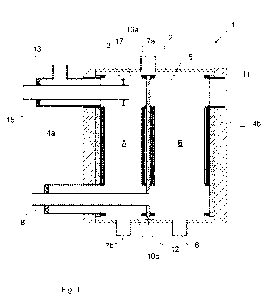
The plate heat exchanger arrangements 1 presented in Figures comprise an
outer casing, which is formed of a substantially horizontal cylindrical shell
3
and substantially vertical first and second end plates 4a, 4b. A plate pack 2
is
arranged inside the outer casing. The plate pack 2 is formed by heat
exchange plates having two openings and arranged on top of each other, in
which plate pack the heat exchange plates are attached to each other as
plate pairs, the inner parts of which plate pairs are arranged in connection
with each other via flow passages 10a, 10b formed by the openings of the
heat exchange plates.
In the embodiments presented in Figures 1-3, a plate pack 2 comprises two
plate pack parts, a first plate pack part A and a second plate pack part B.
The
first and the second plate pack parts are separated from each other by
arranging a partition wall 5 between the heat exchange plates of the plate
pack.
In the embodiments presented in Figures 5 and 6, a plate pack 2 comprises
three plate pack parts, a first plate pack part A, a second plate pack part B
and a third plate pack part C. The plate pack parts are separated from each
CA 03111906 2021-03-05
WO 2020/074641
PCT/EP2019/077474
11
other by arranging two partition walls 5a, 5b between the heat exchange
plates of the plate pack.
In an embodiment presented in Figure 7, a plate pack 2 comprises four plate
pack parts, a first plate pack part A, a second plate pack part B, a third
plate
pack part C and a fourth plate pack part D. The plate pack parts are
separated from each other by arranging three partition walls 5a, 5b, 5c
between the heat exchange plates of the plate pack.
Each plate pack part comprises several plate pairs of the plate pack 2. A
number of the plate pairs may vary and a length of the plate pack parts in a
longitudinal direction of the plate pack 2 may differ form each other.
The partition plate 5, 5a, 5b, 5c is arranged between the heat exchange
plates so that the outer edge of the partition plate is substantially in the
same
plane with the outer surface of the plate pack. A partition plate or plates
arranged between the plate pack parts is used to block a flow connection of
the plate pack parts through the flow passages 10a, 10b. The partition plate
comprises required opening(s) for inlet and/or outlet connections in order
.. forming a connection to the flow passage of said plate pack part.
In Figure 1, one of the connections of the second plate pack part B is
arranged so that the connection comprises a connection pipe 8. The other
connection 11 is arranged through the end plate 4b. A heat exchange
medium circuit of the second plate pack part B is formed between the
connection 11 and the connection pipe 8, a flow direction may be whichever.
A connection pipe 8 is arranged inside a flow passage 10b of the first plate
pack part A, wherein an end of the connection pipe 8 is attached to the
partition plate 5 for forming a connection to the flow passage of the second
plate pack part and a second end of the connection pipe 8 elongates through
the end plate 4a of the outer casing.
In Figure 1, a heat exchange medium circuit of the first plate pack part A is
formed between an inlet connection pipe 15 and the outlet connection 13.
The connection pipe 15 is arranged through the outlet connection 13,
wherein said connection pipe 15 elongates inside the flow passage 10a of
the plate pack. An end of the connection pipe 15 is arranged tightly to flow
CA 03111906 2021-03-05
WO 2020/074641
PCT/EP2019/077474
12
passage e.g. by means of a plate like structure 17. This structure makes
possible to arrange the inlet and the outlet connection of the first plate
pack
part A through the same opening in the end plate of the outer casing and to
provide a heat exchange medium circulation inside the plate pack part A.
In Figure 1, a shell side of plate heat exchanger arrangement comprises one
inlet connection 6 and two outlet connection 7a, 7b. The shell side comprises
two passes, which are formed by a stopper plate 12 arranged between an
outer surface of the plate pack 2 and an inner surface of the shell 3 for
guiding a flow of the shell side heat exchange medium.
In Figure 2, both an inlet connection and an outlet connection of the second
plate pack part B is arranged through the first plate part A. The inlet and
the
outlet connection of the second plate pack part B is formed by arranging a
connection pipe 8, 9 inside the flow passages 10a, 10b of the first plate pack
part A. An end of the connection pipes 8, 9 is attached to the partition plate
5
for forming a connection to said flow passages of the second plate pack part
and a second end of the connection pipes 8, 9 elongates through the end
plate 4a of the outer casing. A heat exchange medium circuit of the second
plate pack part B is formed between the connection pipe 8 and the
connection pipe 9, a flow direction may be whichever. In Figure 2, a shell
side comprises an inlet connection 6 and an outlet connection 7 arranged
through the shell 3 of the outer casing.
Figure 3 shows similar plate pack parts as Figure 2, but the shell side
connections are arranged at the end plate. Figure 4 shows the same
embodiment seen from the end plate 4a of the outer casing. The inlet
connection 6 and the outlet connection 7 of the shell side are arranged
through the end plate 4a of the outer casing. Typically, there is also a flow
guide 16 between the inlet and outlet connections of the shell side for
guiding
the flow of the heat exchange medium to circulate from the inlet connection
to the outlet connection. The connection pipes 8, 9 of the second plate pack
part B are arranged inside the inlet and outlet connections 13, 14 of the
first
plate pack part A, wherein all connections of the plate heat exchanger are
arranged through the same end plate. This provides a compact structure and
enables also an openable structure of the plate heat exchanger.
CA 03111906 2021-03-05
WO 2020/074641
PCT/EP2019/077474
13
In an embodiment presented in Figure 5, one of the connections of the
second plate pack part B is arranged so that the connection comprises a
connection pipe 8, which is arranged inside the flow passages 10b of the first
plate pack part A. The other connection 20 of the second plate pack part B
comprises a connection pipe 20, which is arranged inside the flow passages
10a of the third plate pack part C. A heat exchange medium circuit of the
second plate pack part B is formed between the connection pipe 8 and the
connection pipe 20, a flow direction may be whichever. An end of the
connection pipe 8 is attached to the partition plate 5a and an end of the
connection pipe 20 is attached to the partition plate 5b for forming a
connection to the flow passage of the second plate pack part. A second end
of the connection pipe 8 elongates through the end plate 4a of the outer
casing and a second end of the connection pipe 20 elongates through the
end plate 4b of the outer casing. Inlet and outlet connections of the first
plate
pack part A are similar as presented in Figure 1. Inlet and outlet connections
of the third plate pack part C are corresponding with the inlet and outlet
connections of the first plate pack part A, i.e. a heat exchange medium
circuit
of the first plate pack part A is formed between an inlet connection pipe 22
and the outlet connection 25. The connection pipe 22 is arranged through the
outlet connection 25, wherein said connection pipe 22 elongates inside the
flow passage 10b of the plate pack of the third plate pack part. An end of the
connection pipe 22 is arranged tightly to flow passage e.g. by means of a
plate like structure 17.
In Figure 5, a shell side of plate heat exchanger arrangement comprises an
inlet connection 6 and an outlet connection 7. The shell side comprises three
passes, which are formed by the stopper plates 12a, 12b arranged between
the outer surface of the plate pack 2 and an inner surface of the shell 3 for
guiding a flow of the shell side heat exchange medium.
Figure 6 shows corresponding structure as Figure 5, but the connection pipe
20 of the second plate pack part B is arranged inside the flow passages 10b
of the third plate pack part C. Connection pipes 8, 20 of the second plate
pack part B are now arranged through the same flow passage and so it is
required to arranged a dividing plate 21 inside the flow passage 10b of the
second plate part B for guiding a flow of the heat exchange medium inside
the second plate pack part B.
CA 03111906 2021-03-05
WO 2020/074641
PCT/EP2019/077474
14
Figure 7 shows an embodiment, in which the second plate pack part B and
the third plate pack C comprises inlet and outlet connections which are
arranged through the flow passages of the plate pack parts arranged
between the end plate of the outer casing and the partition wall. A second
plate pack part B comprises connection pipes 8, 9 arranged to the flow
passages of the first plate pack part A, and the third plate pack part C
comprises connection pipes 18, 19 arranged to the flow passages of the
fourth plate pack part D. The connection pipes 8, 9 of the second plate pack
part B are arranged inside the inlet and outlet connections 13, 14 of the
first
plate pack part A, and the connection pipes 18, 19 of the third plate pack
part
C are arranged inside the inlet and outlet connections 23, 24 of the fourth
plate pack part D, wherein all connections of the plate heat exchanger are
arranged through the end plates 4a, 4b.
In an embodiment presented in Figure 7, an inlet and outlet connections 6, 7
of the shell side is also arranged at the end plates 4a, 4b.
As shown in Figures, an outer diameter of the connection pipe 8, 9, 18, 19,
is smaller than a diameter of the flow passage 10a, 10b of the plate pack.
The plate heat exchanger arrangements presented in Figures 1 - 3 may form
a plate heat exchanger as such or they may be a part of the modular
structure. In modular structures, the plate heat exchanger arrangement
presented in Figures 1 ¨ 3 may be one module of the modular structure, and
the end plate 4b forms a partition wall between the arrangement and the
second module of the modular structure.