Note: Descriptions are shown in the official language in which they were submitted.
CA 03111972 2021-03-05
WO 2020/053705
PCT/IB2019/057422
1
"TRACK FOR A TRACKED VEHICLE IN PARTICULAR FOR PREPARING
SKI PISTES , AND THE TRACKED VEHICLE COMPRISING A PLURALITY
OF SAID TRACKS"
CROSS-REFERENCE TO RELATED APPLICATIONS
This Patent Application claims priority from Italian
Patent Application No. 102018000008467 filed on September
10, 2018, the entire disclosure of which is incorporated
herein by reference.
TECHNICAL FIELD
The present invention concerns a track for a tracked
vehicle, in particular for the preparation of ski pistes,
and the tracked vehicle comprising a plurality of said
tracks.
BACKGROUND ART
Generally, a tracked vehicle for the preparation of ski
pistes comprises two rear wheels driven by an engine; two
front wheels; at least two support wheels placed between the
rear wheels and the front wheels; and two tracks, each of
which is wound in a ring between a respective front wheel
and a respective rear wheel. Each track comprises an inner
face and an outside face which, in use, is arranged in
contact with the ground. In addition, the tracked vehicle
for the preparation of ski pistes is equipped with a snow
cutter that is mounted behind it and that is configured for
CA 03111972 2021-03-05
WO 2020/053705
PCT/IB2019/057422
2
grooming snow and creating a ski piste.
One drawback of the prior art is that in use, blocks of
snow and/or ice can accumulate inside the track between the
inner face of the track and around the support wheels and/or
the front wheels and/or the rear wheels. These blocks of
snow and/or ice can escape the track to the side of the
tracked vehicle in an uncontrolled manner and ruin the
preparation of the ski piste because said blocks are not
captured and processed by the snow cutter. This can result
in an imperfect finish of the snow and/or in additional
preparation time and costs for a ski piste, because the
operator has to go over the freshly groomed snow to avoid
leaving blocks of snow and/or ice on the ski piste.
DISCLOSURE OF INVENTION
The purpose of the present invention is a track for a
tracked vehicle in particular for the preparation of ski
pistes that reduces the drawbacks of the known art.
According to the present invention, a track is made for
a tracked vehicle, in particular for the preparation of ski
pistes; the track being configured to be wound around one
respective rear wheel and one front wheel of the tracked
vehicle; the track comprising an outside face which, in use,
is in contact with the ground while the tracked vehicle moves
forward; one inner face on the back side of the outside face
and which, in use, is not in contact with the ground; one
CA 03111972 2021-03-05
WO 2020/053705
PCT/IB2019/057422
3
first lateral end that, in use, is faced to the outside of
the tracked vehicle; a second lateral end that, in use, is
faced to the inner side of the tracked vehicle; at least one
first belt configured to be wound around the rear wheel and
the front wheel and extending in the tracked vehicle's
forward direction; a plurality of crosslinks transverse to
the forward direction connected to at least the first belt
and along the outside face of the track, the crosslinks
preferably being metal; a guide assembly connected along the
inner face of the track and configured to define a seat
assembly for the front wheel and the rear wheel; and cutting
devices connected along the inner face of the track and
positioned closer to the first lateral end than the guide
assembly.
Thanks to the present invention, large blocks of snow
or ice escaping from the side of the tracks are avoided, in
fact the cutters keep the large blocks of ice inside the
track or crumble them into small blocks of ice that can be
treated by the cutter or even left on the ski piste, as they
do not have a great impact on the overall quality of the
finish of the ski piste.
According to a preferred embodiment of the present
invention, the track comprises a plurality of belts,
preferably of at least partly elastomeric material,
comprising at least the first belt and that extend in the
CA 03111972 2021-03-05
WO 2020/053705
PCT/IB2019/057422
4
forward direction and wherein the crosslinks are connected
to the plurality of belts.
According to another preferred embodiment, the guide
assembly comprises a plurality of guide elements connected
along the inner face of the track, preferably each guide
element is connected to a respective crosslink of the
plurality of crosslinks along the inner face of the track.
According to another preferred embodiment, the
crosslinks are connected to at least one belt through fixing
means, in particular through plates and bolts.
According to another preferred embodiment, each cutting
device is connected along the inner face of the track and
comprises a first end connected to a belt of the plurality
of belts and a second end connected to another belt of the
plurality of belts preferably through at least part of the
fixing means that connect the belts to the crosslinks.
According to another preferred embodiment, each cutting
device is connected along the inner face of the track and in
particular in contact with one of the belts of the plurality
of belts and comprises a first end connected to the said
belt and a second end connected to the said belt, preferably
through at least part of the fixing means.
According to another preferred embodiment, each cutting
device is connected along the inner face of the track and in
particular is connected to the cross bar along an inner face
CA 03111972 2021-03-05
WO 2020/053705
PCT/IB2019/057422
of the cross bar; the inner face of the cross bar is on the
back side of the face of the cross bar that is in contact
with the ground; in particular the cutting device being
directly connected to the cross bar through fixing elements.
5
According to another preferred embodiment, each cutting
device comprises a base connected to the inner face of the
track and a cutter connected to the base.
According to another preferred embodiment, the cutter
is connected to the base through a hinge so that the cutter
can rotate around an axis between a rest position and a work
position, wherein, in use, the cutter is configured to cut
blocks of ice or snow.
According to another preferred embodiment, the base
comprises a stop that abuts against the cutter in the work
position.
According to another preferred embodiment, the cutter
comprises a main body able to cut and two wings that extend
on a plane perpendicular to the plane on which the main body
extends.
According to another preferred embodiment, the cutter
is formed from a single piece, in particular from a folded
metal sheet so that the main body is formed from two layers
of the metal sheet and the wings are formed from a single
layer of the metal sheet.
According to another preferred embodiment, the base is
CA 03111972 2021-03-05
WO 2020/053705
PCT/IB2019/057422
6
connected at one end to one belt of the plurality of belts
and at another end to another belt of the plurality of belts.
According to another preferred embodiment, the cutter
comprises a main body able to cut and two wings that extend
on a plane perpendicular to the plane on which the main body
extends, and in which the stop abuts against the wings of
the cutter when the cutter is in the work position.
According to another preferred embodiment, the hinge
that connects the base to the cutter has a rotation axis,
which is transversal, in particular perpendicular, to the
forward direction.
Another purpose of the present invention is to create
a tracked vehicle, in particular for the preparation of ski
pistes that reduces at least one of the drawbacks of the
known art.
According to the present invention a tracked vehicle is
made, in particular for the preparation of ski pistes; the
tracked vehicle comprising: a frame; two rear wheels
supported by the frame; two front wheels supported by the
frame; a plurality of tracks, preferably two, each of which
as claimed in any of the claims from 1 to 12; and in which
each track is wound around one respective rear wheel and one
respective front wheel.
According to a preferred embodiment, in which the
tracked vehicle comprises two pluralities of support wheels;
CA 03111972 2021-03-05
WO 2020/053705
PCT/IB2019/057422
7
each plurality of support wheels is arranged between one of
the respective front wheels and one of the respective rear
wheels; each track being wound around one of the respective
front wheels, one of the respective plurality of support
wheels, and one of the respective rear wheels.
According to a preferred embodiment, the guide
assemblies of each track are in contact with the support
wheels.
BRIEF DESCRIPTION OF THE DRAWINGS
Further characteristics and advantages of the present
invention will become clear from the following description
of its non-limiting examples of embodiments, with reference
to the accompanying figures, wherein:
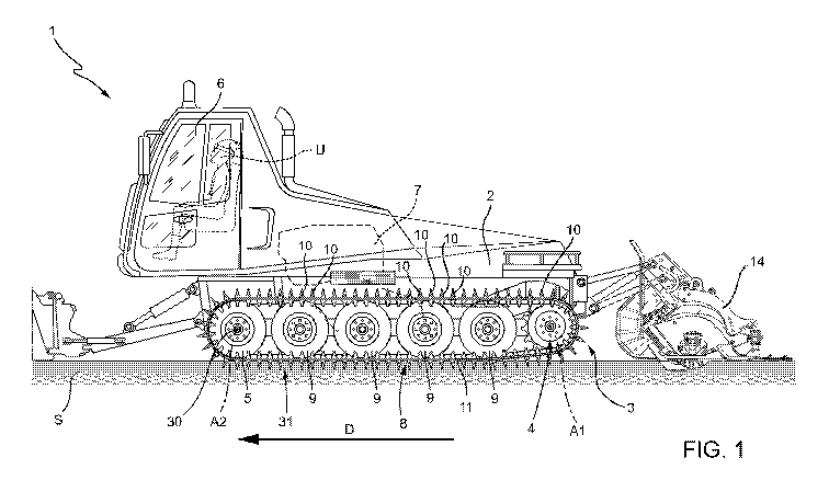
- Figure 1 is a lateral elevation view, with some parts
removed for clarity, of a tracked vehicle configured for the
preparation of ski pistes provided with tracks in accordance
with the present invention;
- Figure 2 is an upper elevation view of the tracked
vehicle, and of the tracks of Figure 1, with some parts
removed for clarity;
- Figure 3 is an enlarged perspective elevation view of
one of the tracks of Figure 1, with some parts removed for
clarity;
- Figure 4 is a cross-sectional view of Figure 3, with
some parts removed for clarity and on an enlarged scale;
CA 03111972 2021-03-05
WO 2020/053705
PCT/IB2019/057422
8
- Figure 5 is a perspective view of a cutting device in
a work position and made according to the present invention;
- Figure 6 is a perspective view of the cutting device
of Figure 5 but in a rest position and made according to the
present invention;
- Figure 7 is an enlarged perspective elevation view of
an alternative embodiment of the present invention, with
some parts removed for clarity; and
- Figure 8 is an enlarged perspective elevation view of
an alternative embodiment of the present invention, with
some parts removed for clarity.
BEST MODE FOR CARRYING OUT THE INVENTION
With reference to Figure 1, a tracked vehicle for the
preparation of ski pistes, in particular a snow groomer, is
designated as a whole by the number 1.
The tracked vehicle 1 comprises a frame 2; two tracks
3 (only one of which is illustrated in Figure 1); two rear
wheels 4 (only one of which is illustrated in Figure 1)
rotatable about a rotation axis Al; two front wheels 5 (only
one of which is illustrated in Figure 1) rotatable about a
rotation axis A2 that is parallel to the axis Al; a cab 6;
and an engine 7. The rear wheels 4 are drive wheels driven
independently of one another by actuators, preferably of the
hydraulic or electric or mechanical type, and are coupled to
the respective tracks 3.
CA 03111972 2021-03-05
WO 2020/053705
PCT/IB2019/057422
9
With reference to Figures 1 and 2, the tracked vehicle
1 comprises a snow cutter 14 positioned at the rear of the
tracked vehicle 1 and that extends laterally across a greater
dimension than the lateral dimension of the tracked vehicle
1 and of the tracks 3.
Each track 3 is wound in a ring between one of the
respective two rear wheels 4 and one of the respective two
front wheels 5. In other words, the rear wheel 4 and the
front wheel 5 engage the track 3, along an inner face 30 of
the track 3. The inner face 30, in use, is not in contact
with the ground S. Each track 3 has an outside face 31 which
is on the back side of the inner face 30 and which, in use,
is in contact with the ground S while the tracked vehicle 1
moves forward.
The tracked vehicle 1 comprises two pluralities of
support wheels 9, in particular a plurality for each track
3. In other words, each track 3 cooperates with the support
wheels 9 arranged in sequence between the front wheel 5 and
the rear wheel 4. The support wheels 9 are arranged inside
the ring of the respective track 3 between the respective
rear wheel 4 and the respective front wheel 5 to distribute
the mass of the tracked vehicle 1 along the traction portion
8 of the track 3, and to compress a traction portion 8 of
the track 3 itself against the ground S in order to achieve
greater adherence to the ground S and to reduce any slipping
CA 03111972 2021-03-05
WO 2020/053705
PCT/IB2019/057422
of the track 3 on the ground S. The support wheels 9 are in
contact with the inner face 30 of the respective track 3.
With reference to Figures 1 and 3, each track 3
comprises a plurality of crosslinks 10 arranged transversely
5 to the forward direction D and a plurality of belts 11 made
of an elastomeric material, in particular rubber, to which
the crosslinks 10 are fixed spaced apart from each other
along the forward direction D. In one embodiment the belts
11 comprise composite elastomeric material, for example,
10 with internal fibres.
Each crosslink 10 comprises a crampon and is clamped to
the belts 11 through fixing means 12, in particular metal
plates and bolts. Thus, the crosslinks 10 also have the
function of keeping the belts 11 spaced apart from each
other. With reference to Figures 1, 2 and 3, the belts 11
are wound in a ring and arranged side-by-side along an axis
parallel to the axis Al or A2 and extend along a direction
parallel to the forward direction D. In a preferred
embodiment, each track 3 comprises a number of belts 11
varying between two and eight. In another embodiment, each
belt 11 is composed of portions of belt which joined together
form the belt 11 wound in a ring.
With reference to Figures 1 and 4, each track 3
comprises guides 13 which are arranged along the inner face
30 of the track 3. The set of guides 13 of each track 3
CA 03111972 2021-03-05
WO 2020/053705
PCT/IB2019/057422
11
defines a guide assembly. Each guide 13 is clamped to one of
the respective crosslinks 10. The guides 13 define the
coupling seats with the support wheels 9 and with the front
wheels 5 and the rear wheels 4. In particular the guides 13
are configured to keep the support wheels 9 in the correct
position inside the respective track 3.
The support wheels 9 are arranged inside the ring of
the track 3 and each has a rotation axis parallel to the
rotation axis Al of the rear wheel 4.
In a particular, non-limiting embodiment of the present
invention, not illustrated in the attached figures, the
plurality of wheels are mounted in pairs on a respective
structure. In more detail, the structure is a rocker arm
that houses one support wheel of the pair of support wheels
at its opposite ends. The structure in turn is connected by
a rotating connection to the frame of the tracked vehicle.
In addition, with reference to Figures 2 to 4, each
track 3 comprises a lateral end 20 which, in use, is faced
to the outside of the tracked vehicle 1; and a lateral end
21 which, in use, is faced to the inner side of the tracked
vehicle 1; and a plurality of cutting devices 40 connected
along the inner face 30 of the track 3 and positioned closer
to the lateral end 20 than the guides 12.
With reference to Figure 4, each cutting device 40 is
connected along the inner face 30 of the track 3 between two
CA 03111972 2021-03-05
WO 2020/053705
PCT/IB2019/057422
12
belts 11 through part of the fastening means 12 that connect
the belts 11 to the crosslinks 10.
With reference to Figures 4, 5 and 6, each cutting
device 40 comprises a base 41 connected to the inner face 30
of the track 3, and a cutter 42 connected to the base 41
through a hinge 43 so that the cutter 42 can rotate around
an axis A3 between a work position PL as illustrated in
Figure 5, and a rest position PR as illustrated in Figure 6.
In more detail, in the work position PL, the cutter 42 is
positioned perpendicularly to the forward direction D and
extends from the base 41 and from the track 3 perpendicularly
to them. In the rest position PR, the cutter 42 is positioned
parallel to the forward direction D, so that the track 3,
when not connected to the tracked vehicle 1, can be easily
rolled up for transport or storage.
In addition, with reference to Figure 5, the base 41 of
the cutting device 40 comprises a stop 44, which abuts
against the cutter 42 in the work position PL. In addition,
the cutter 42 comprises a main body 45 able to cut and two
wings 46 extending on a plane perpendicular to the plane on
which the main body 45 lies. The cutter 42 is formed from a
single piece, in particular a folded metal sheet, so that
the main body 45 is formed from two layers of the metal sheet
and the wings 46 are formed from a single layer of the metal
sheet.
CA 03111972 2021-03-05
WO 2020/053705
PCT/IB2019/057422
13
In an alternative embodiment of the invention, the
cutting device 40, in particular the base 41 and the cutter
42, is produced through forging or fusion.
With reference to Figure 5, the stop 44 abuts against
the wings 46 of the cutter 42 when the cutter 42 is in the
work position PL.
With reference to Figure 4, the base 41 comprises one
end 47 connected to one of the belts 11 and another end 48
connected to another of the belts 11 through the metal plates
12, which connect the belts 11 to the crosslinks 10.
In an alternative embodiment, not illustrated in the
attached figures, the base is connected, preferably
directly, to one of the crosslinks. In other words, in this
embodiment, each cutting device is connected along the inner
face of the track and in particular is connected to a
respective crosslink of the plurality of crosslinks along an
inner face of the cross bar. In more detail, the cutting
device is directly connected to the crosslink 10 through
fixing elements.
In another embodiment illustrated in Figure 7, each
cutting device 40 is connected along the inner face 30 of
the track 3 and in particular in contact with one of the
belts 11 of the plurality of belts 11 and comprises one end
47 connected to said belt 11 and another end 48 connected to
the same said belt 11 through part of the fixing means 12,
CA 03111972 2021-03-05
WO 2020/053705
PCT/IB2019/057422
14
in particular the bolts. In particular, in this embodiment,
the entire base 41 of the cutting device 40 is connected to
said belt 11, and in particular to a single said belt 11.
In another embodiment of the present invention
illustrated here, the different ways of connecting the
cutting devices inside the track, as described above, can be
combined with each other. For example, Figure 8 illustrates
one embodiment wherein some cutting devices 40 are connected
to a single belt 11 and other cutting devices 40 are
connected between two belts 11. Another embodiment of the
present invention requires that some cutting devices are
connected between two belts and others directly to the cross
bar from the inner side of the track. Another embodiment of
the present invention requires that some cutting devices are
connected to a single belt and others to the cross bar from
the inner side of the track. Another embodiment of the
present invention requires that some cutting devices are
connected between two belts, other cutting devices are
connected to the cross bar on the inner side of the track
and other cutting devices still are connected to a single
belt.
In addition, with reference to Figures 4, 5 and 6, in
the work position PL the hinge 43, which connects the base
41 and the cutter 42, having the rotation axis A3, which is
transversal, in particular perpendicular, to the forward
CA 03111972 2021-03-05
WO 2020/053705
PCT/IB2019/057422
direction D prevents the blocks of snow or ice from escaping
externally from the tracked vehicle 1, or cuts these blocks
of snow or ice into smaller pieces that do not significantly
affect the snow and/or its grooming.
5
Finally, in a preferred embodiment not illustrated in
the attached figures, the cutting devices can be held in the
work position PL or in the rest position PR through a locking
element or through a spring element, in particular a load
spring.
10 The
scope of protection of the present invention is
defined by the claims which cover variants not specifically
described and equivalent embodiments.