Note: Descriptions are shown in the official language in which they were submitted.
A1174.70097US00
- 1 -
PUSH THROUGH LATCH
FIELD
[0001] Disclosed embodiments are related to door locks, and in particular
push
through latches and related methods of use.
BACKGROUND
[0002] Bored locks are commonly employed on doors to secure the doors.
Conventional bored locks employ a linearly translating latch bolt which
typically includes a
strike face that allows a door to be closed without retracting the latch and a
locking face that
prevents the door from being opened without first retracting the latch. In
some cases,
electronic bored locks have been employed which electromechanically retract
the latch.
SUMMARY
[0003] In some embodiments, a door lock includes a latch bolt head having a
strike
face and a locking face. The latch bolt head is moveable along a first axis
between an
extended position and a retracted position, and the latch bolt head is movable
between a first
rotational position and a second rotational position. In the first rotational
position, the locking
face is parallel to the first axis, and in the second rotational position the
locking face is angled
relative to the first axis. The door lock also includes a blocking pin
configured to move
between an engaged position and a disengaged position, where in the engaged
position the
blocking pin prevents the latch bolt from moving from the first rotational
position to the
second rotational position.
[0004] In some embodiments, a door lock includes a latch bolt head having a
strike
face and a locking face, where the latch bolt head is moveable along a first
axis between an
extended position and a retracted position. The latch bolt head is also
movable between a first
rotational position and a second rotational position. In the first rotational
position, the locking
face is configured to engage a latch head pocket to prevent the opening of an
associated door,
and in the second rotational position the locking face is configured to strike
a latch head
pocket and move the latch bolt head from the extended position to the
retracted position. The
door lock also includes a blocking pin configured to move between an engaged
position and a
7977274.1
Date Recue/Date Received 2021-03-17
- 2 -
disengaged position, where in the engaged position the blocking pin prevents
the latch bolt
from moving from the first rotational position to the second rotational
position.
[0005] In some embodiments, a method of locking and unlocking a door
includes
striking a latch head pocket of a door jamb with a strike face of a latch bolt
head to move the
latch bolt head from an extended position to a retracted position, moving the
latch bolt head
from the retracted position to an extended position where the latch bolt head
is at least
partially disposed in the latch head pocket, unblocking the latch bolt head
from moving from
a first rotational position to a second rotational position, rotating the
latch bolt head from the
first rotational position to the second rotational position, and striking the
latch head pocket of
the door jamb with a locking face of the latch bolt head to move the latch
bolt head from the
extended position to the retracted position.
[0006] It should be appreciated that the foregoing concepts, and additional
concepts
discussed below, may be arranged in any suitable combination, as the present
disclosure is
not limited in this respect. Further, other advantages and novel features of
the present
disclosure will become apparent from the following detailed description of
various non-
limiting embodiments when considered in conjunction with the accompanying
figures.
BRIEF DESCRIPTION OF DRAWINGS
[0007] The accompanying drawings are not intended to be drawn to scale. In
the
drawings, each identical or nearly identical component that is illustrated in
various figures
may be represented by a like numeral. For purposes of clarity, not every
component may be
labeled in every drawing. In the drawings:
[0008] FIG. 1 is a perspective view of one embodiment of a push through
latch;
[0009] FIG. 2 is a perspective view of the push through latch of FIG. 1
shown with a
transparent latch bolt head housing;
[0010] FIG. 3 is a cutaway view of the push through latch of FIG. 1 in a
first state;
[0011] FIG. 4 is a cutaway view of the push through latch of FIG. 1 in a
second state;
[0012] FIG. 5 is a cutaway view of the push through latch of FIG. 1 in a
third state;
[0013] FIG. 6 is a cutaway view of the push through latch of FIG. 1 in a
fourth state;
[0014] FIG. 7 is a cutaway view of the push through latch of FIG. 1 in a
fifth state;
7977274.1
Date Recue/Date Received 2021-03-17
- 3 -
[0015] FIG. 8 is a cutaway view of the push through latch of FIG. 1 in a
sixth state;
[0016] FIG. 9 is a top schematic view of another embodiment of a push
through latch
in a first state;
[0017] FIG. 10 is a top schematic view of the push through latch of FIG. 9
in a
second state;
[0018] FIG. 11 is a top schematic view of the push through latch of FIG. 9
in a third
state;
[0019] FIG. 12 is a top schematic view of the push through latch of FIG. 9
in a fourth
state;
[0020] FIG. 13 is a top schematic view of the push through latch of FIG. 9
in a fifth
state;
[0021] FIG. 14 is a first side view of one embodiment of a door including a
push
through latch of exemplary embodiments described herein; and
[0022] FIG. 15 is an edge view of the door of FIG. 14.
DETAILED DESCRIPTION
[0023] Conventional bored locks employ a linearly translating latch bolt
which
typically includes an inclined face that allows a door to be closed without
retracting the latch
and a locking face that prevents the door from being opened without first
retracting the latch.
In some cases, electronic bored locks have been employed which
electromechanically retract
the latch. However, electromechanical retraction may be energy intensive,
oftentimes
requires significant power to overcome the biasing forces of springs commonly
found in
board locks. Additionally, as bored locks often occupy a small volume inside
of a door (in
contrast to mortise locks), there is oftentimes little volume for energy
storage (e.g., batteries,
capacitors), conventional solutions for electromechanically actuated bored
locks may be
limited in off-grid applications. That is, conventional electromechanical
actuators for bored
locks may have limited battery life due to power draw required for retracting
conventional
latch bolt heads.
[0024] In view of the above, the inventors have recognized the benefits of
a push
through latch that employs a rotatable latch bolt head. The rotation of the
rotatable latch bolt
head may be controlled by a blocking pin or other blocker that may be moved
with low
7977274.1
Date Recue/Date Received 2021-03-17
- 4 -
energy input from an electromechanical actuator or manual actuator. By
allowing the latch
head to rotate, a strike face and a locking face may swap angles, such that
the locking face
retracts the bolt when a closed door is pushed open. Accordingly, such an
arrangement may
reduce the energy draw for retracting a latch by an electromechanical actuator
or manually by
a user.
[0025] In some embodiments, a push through latch includes a latch bolt head
and a
blocker (e.g., a blocking pin). The latch bolt head is configured to move
substantially linearly
along a first axis between an extended position and a retracted position. In
some
embodiments, the latch bolt head may be rotatably coupled to a latch bolt head
housing with
a pin, such that the latch bolt head and latch bolt head housing move together
between the
extended position and the retracted position. The latch bolt head may be
rotatable about the
pin between a first rotational and a second rotational position relative to
the latch bolt head
housing. The rotation of the latch bolt head may be controlled by the blocker,
which may
move between an engaged position and a disengaged position. In the engaged
position, the
blocker may engage the latch bolt head to inhibit the latch bolt head from
moving to the
second rotational position. In the disengaged position, the blocker may
disengage the latch
bolt head to allow the latch bolt head to rotate about the pin to the second
rotational position.
The latch bolt head may include a strike face and a locking face. In the first
rotational
position, the strike face may be inclined relative to the first axis while the
locking face is
substantially parallel to the first axis. In this arrangement, the strike face
may be configured
to contact a latch head pocket of a door jamb to move the latch bolt head from
the extended
position to the retracted position. The locking face is configured to engage
the latch head
pocket of the door jamb to prevent an opening of a door when the latch bolt
head is in an
extended position inside of the latch head pocket. However, when the latch
bolt head is
passively rotated to the second rotational position, the locking face and
strike face swap
angles. That is, the locking face may be passively rotated so that is inclined
relative to the
first axis, in a direction opposite the previous incline of the strike face.
Accordingly, when the
locking face engages the latch head pocket, the locking face may move the
latch bolt head
from the extended position to the retracted position. In this manner, the push
through latch
may allow a door lock to be opened without manually or electromechanically
retracting the
7977274.1
Date Recue/Date Received 2021-03-17
- 5 -
latch bolt head, as once the push through latch is allowed to rotate to the
second rotational
position, the associated door may be pushed or pulled open.
[0026] In some embodiments, a push through latch according to exemplary
embodiments described herein may be actuated using one or more actuators. In
some
embodiments, an actuator may include a mechanical actuator such as a push
button or switch.
The button or switch may be disposed on an interior door handle or interior
escutcheon (i.e.,
on the secure side of a door). Accordingly, a user may operate the button or
switch on the
interior door handle or escutcheon and simply push the door to retract the
latch and open the
door. That is, a user may not have to turn a handle, as would be the case on a
conventional
bored lock. In some embodiments, the actuator may include an electromechanical
actuator
such as a solenoid, servo, or linear actuator. The electromechanical actuator
may be
configured to selectively actuate the blocking pin or other blocker to allow a
door to be
opened with a simple push without having to turn a handle. Accordingly, the
electromechanical actuator may not retract the latch, thereby reducing the
energy
consumption of the electromechanical actuator to open a door, and instead
simply move the
blocker out of the way to allow the latch to rotate or move. In some
embodiments, the
electromechanical actuator may receive commands from a processor and/or a
remote device,
as will be discussed further below.
[0027] In some embodiments, door locks including push through latches of
exemplary embodiments described herein may be controlled locally and/or
remotely with one
or more complementary devices. In some embodiments, a door lock may include a
processor
configured to execute computer readable instructions stored in memory. The
processor may
be electrically connected to an electromechanical actuator and configured to
control the
operation of the electromechanical actuator. The processor may also be
configured to
communicate with one or more complementary devices via one or more networks.
For
example, the processor may be electrically connected to a wireless transceiver
that may send
and receive wireless signals via one or more wireless protocols (e.g.,
Bluetooth, Wi-Fi,
802.15.4, Z-Wave, Bluetooth Low-Energy, NFC, RFID, GSM, CDMA). Accordingly,
one or
more complementary devices communicating over one or more wireless protocols
or through
the internet may command the processor to operate an electromechanical
actuator. The one or
7977274.1
Date Recue/Date Received 2021-03-17
- 6 -
more complementary device may include, but are not limited to, smartphones,
personal
computers, tablets, and servers.
[0028] Turning to the figures, specific non-limiting embodiments are
described in
further detail. It should be understood that the various systems, components,
features, and
methods described relative to these embodiments may be used either
individually and/or in
any desired combination as the disclosure is not limited to only the specific
embodiments
described herein.
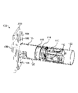
[0029] FIG. 1 is a perspective view of one embodiment of a push through
latch 100 of
a door lock. As shown in FIG. 1, the push through latch includes a latch
housing 102 (shown
transparently for clarity) and a door plate 104 having two fastening holes
106. The door plate
and fastening holes may be used to rigidly secure the latch housing 102 in a
door (e.g., with
fasteners such as screws). As shown in FIG. 1, the push through latch 100 also
includes a
latch bolt head 108 projecting from the door plate 104. According to the
embodiment of FIG.
1, the latch bolt head 108 is configured to both move between an extended and
retracted
position as well as a first rotational position and a second rotational
position, as will be
discussed further with reference to FIGs. 2-8. In the embodiment of FIG. 1,
the push through
latch also includes a handle actuator 110 having a handle coupler 112. The
handle actuator is
coupled to the latch bolt head 108 and is configured to move the latch bolt
head between the
extended position and retracted position within the latch housing 102. The
handle coupling is
configured to receive a handle 402 (see FIG. 8) of a door lock, where rotating
the handle
moves the handle actuator 110 by a camming action. According to the embodiment
of FIGs.
1 and 2, the latch bolt head 108 is coupled to a latch bolt head housing 116.
In particular, the
latch bolt head 108 is rotatably coupled to the latch bolt head housing with a
pin 124 so that
the latch bolt head is able to rotate relative to the latch bolt head housing,
but the latch bolt
head housing and latch bolt head move together between the extended and
retracted position.
As shown in FIG. 1, the latch bolt head housing includes a spring receiving
portion 118
configured to receive a compression spring 114. The compression spring 114
couples the
handle actuator 110 to the latch bolt head housing 116, allowing the handle
actuator 110 to
move the latch bolt head housing 116 between the extended and retracted
positions. The
compression spring 114 also functions to bias the latch bolt head 108 toward
the extended
position. Of course, while a compression spring 114 is employed in the
embodiment of FIG.
7977274.1
Date Recue/Date Received 2021-03-17
-7-
1, any suitable biasing member may be employed to couple the handle actuator
110 to the
latch bolt head 108, as the present disclosure is not so limited. As shown in
FIG. 1, the push
through latch 100 also includes a latch bolt head biasing plunger 120 which
biases the latch
bolt head 108 toward the first rotational position.
[0030] According to the state shown in FIG. 1, the latch bolt head 108 is
in the
extended position and first rotational position. Accordingly, the latch bolt
head 108 is
projecting through a strike plate 200 of an associated latch head pocket.
Accordingly, the
push through latch may secure a door when in the state of FIG. 1.
[0031] FIG. 2 is a perspective view of the push through latch 100 of FIG. 1
with a
latch bolt head housing shown in transparent for clarity to reveal the
internal components of
the push through latch. As noted with reference to FIG. 1, the push through
latch includes a
latch bolt head 108 which is movable between an extended and retracted
position by a handle
actuator 110. The latch bolt head 108 is coupled to the handle actuator 110
via a compression
spring 114. As discussed previously, the latch bolt head 108 is rotatably
coupled to the latch
bolt head housing with a pin 124. Accordingly, the latch bolt head 108 moves
linearly inside
of the latch housing 102 between the extended position and retracted position
with the latch
bolt head housing. As shown in FIG. 2, the latch bolt head biasing plunger 120
urges the latch
bolt head 108 to the first rotational position shown in FIGs. 1-2 via
compression spring 122
disposed between the latch bolt head biasing plunger and the latch bolt head
housing.
[0032] According to one embodiment as best shown in FIG. 2, the push
through latch
100 includes a blocking pin 126 configured to selectively inhibit or allow
rotation of the latch
bolt head 108 between the first rotational position and a second rotational
position. That is,
the blocking pin 126 is configured to move between an engaged position where
the blocking
pin inhibits rotation of the latch bolt head and a disengaged position where
the blocking pin
allows rotation of the latch bolt head. The blocking pin of FIG. 2 moves in a
direction parallel
to a direction of movement of the latch bolt head 108 between the extended
position and
retracted position. The blocking pin includes a blocking projection 127
configured to engage
a slot 109 formed on the latch bolt head when the blocking pin is in the
engaged position.
When the blocking projection 127 is engaged with the slot 109, the
interference between the
blocking projection and the slot 109 inhibits rotation of the latch bolt head
108 about the pin
124. Of course, while a slot 109 is shown in the embodiment of FIG. 2, any
suitable feature
7977274.1
Date Recue/Date Received 2021-03-17
- 8 -
of the latch bolt head (e.g., projection, shelf, recess) may engage the
blocking projection 217,
as the present disclosure is not so limited. According to the embodiment shown
in FIG. 2, the
blocking pin 126 is biased toward the engaged position with a blocking pin
spring 130.
According to some embodiments as shown in FIG. 2, the blocking pin spring 130
biases the
blocking pin 126 relative to the latch head housing, such that the blocking
pin moves with the
latch bolt head 108 between the extended and retracted positions.
[0033] According to some embodiments as shown in FIG. 2, the push through
latch
100 includes a deadlatching plunger 132 configured to deadlatch the push
through latch to
inhibit opening the push through latch via a force applied externally to the
latch bolt head
108. That is, the deadlatching plunger inhibits common attacks such as carding
the latch bolt
head 108 from moving the latch bolt head 108 from the extended position to the
retracted
position. As shown in FIG. 2, the deadlatching plunger includes a deadlatching
pin 134
configured to selectively engage the latch housing 102. The deadlatching
plunger 132 also
includes a spacer 136 which controls the engagement of the deadlatching pin
134 with the
latch housing 102. The deadlatching plunger moves between a free position and
a
deadlatching position. The free position of the deadlatching plunger
corresponds to an
extended position, whereas the deadlatching position corresponds to a
retracted position
relative to the latch housing 102. The deadlatching plunger is held in the
deadlatching
position when the push through latch 100 is aligned with a latch head pocket.
In particular,
the deadlatching plunger is configured to engage the strike plate 200 of the
latch head pocket
which moves the deadlatching plunger from the free position to the
deadlatching position.
When the deadlatching plunger is in the deadlatching position, the spacer 136
engages the
deadlatching pin 134 to move the deadlatching pin radially outward (i.e.,
transverse to a
longitudinal axis of the latch housing) to engage the latch housing 102 and
the latch head
housing. Accordingly, in the deadlatching position the deadlatching plunger
inhibits relative
movement of the latch head housing and the latch 102, such that the latch bolt
head 108 may
not move from the extended position to the retracted position. The spacer 136
is urged into
contact with the deadlatching pin 134 by a coupling ball 140 disposed between
the
deadlatching plunger 132 and the blocking pin 126. The coupling ball 140 abuts
the blocking
pin 126 and the spacer 136, thereby applying force to the deadlatching pin 134
to secure the
latch bolt head housing relative to the latch housing 102. As shown in FIG. 2,
the
7977274.1
Date Recue/Date Received 2021-03-17
- 9 -
deadlatching plunger 132 is biased toward the free position by a compression
spring 138.
Similar to the blocking pin 126, the compression spring 138 biases the
deadlatching plunger
relative to the latch bolt head housing, such that the deadlatching plunger
moves with the
latch bolt head 108 between the extended position and retracted position. In
some
embodiments, the deadlatching plunger moves in a direction parallel to a
direction of
movement of the latch bolt head between the extended position and retracted
position.
[0034] According to some embodiments as shown in FIG. 2, the deadlatching
pin 134
is configured to be disengaged from the latch bolt head housing and latch
housing 102 based
on movement of the blocking pin 126. As shown in FIG. 2, the blocking pin 126
includes a
recess 128. The recess 128 is configured to selectively capture the coupling
ball 140 disposed
between the blocking pin 126 and the spacer 136 of the deadlatching plunger
132. When the
blocking pin 126 is in the engaged position shown in FIG. 2, the coupling ball
is not aligned
with the recess 128, such that the coupling ball 140 urges the deadlatching
pin 134 into
engagement with the latch head housing and latch housing 102 via the spacer
136. However,
when the blocking pin 126 is moved to the disengaged position, the coupling
ball 140 is
received in the recess 128, thereby allowing the deadlatching pin 134 to move
out of
engagement with the latch bolt head housing and the latch housing 102.
Accordingly,
operation of the blocking pin 126 (e.g., via an actuator), may release the
latch bolt head 108
and allow the latch bolt head to move to the retracted position.
[0035] FIGs. 3-8 depict cutaway views of the push through latch 100 in
various states
of operation. In particular, FIG. 3 depicts the push through latch in a state
associated with
being engaged with a latch head pocket, and FIG. 4 depicts the push though
latch in a state
associated with moving the blocking pin 126 to a disengaged position. FIG. 5
depicts the
push through latch in a state associated with the latch bolt head 108 being
moved to the
second rotational position, and FIG. 6 depicts the push through latch in a
retracted state
associated with pushing a door open after the latch bolt head 108 is rotated
to the second
rotational position. FIG. 7 depicts the push through latch in an extended
state associated with
the push through latch being disposed outside of a latch head pocket, and FIG.
8 depicts the
push through latch in a retracted state associated with the push through being
retracted as a
door is closed, before the latch extends into a latch head pocket.
7977274.1
Date Recue/Date Received 2021-03-17
- 10 -
[0036] FIG. 3 is a cutaway view of the push through latch 100 of FIG. 1 in
a first state
associated with the latch bolt head 108 being engaged with a latch head
pocket. As discussed
previously with reference to FIG. 2, in the state of FIG. 3, the latch bolt
head is in an
extended position and a first rotational position. The blocking pin 126 is in
the engaged
position, with a blocking projection 127 being engaged with a slot 109 of the
latch bolt head
108. The blocking projection 127 inhibits rotation of the latch bolt head 108
about the pin
124, such that the latch bolt head is limited to linear movement between the
extended position
and retracted position. However, the deadlatching plunger 132 is in a
deadlatching position,
and the spacer 136 and coupling ball 140 urge the deadlatching pin 134 into
engagement with
the latch housing 102 and the latch bolt head housing 116 to inhibit the latch
bolt head from
moving to the retracted position from the extended position.
[0037] According to some embodiments as shown in FIG. 3, the latch bolt
head 108
includes a strike face 142 and a locking face 144 opposite the strike face
142. When the latch
bolt head 108 is in the first rotational position shown in FIG. 3, the strike
face 142 is inclined
relative to a direction of movement of the latch bolt head 108 between the
extended position
and retracted position. Put another way, the strike face is inclined relative
to a longitudinal
axis of the latch housing 102 (e.g., a first axis). Accordingly, when the
strike face 142 strikes
a strike plate or a portion of a door jamb when an associated door is moved in
a closing
direction, a force acting on strike face 142 may urge the latch bolt head from
the extended
position to the retracted position to allow the latch bolt head to clear the
strike plate or door
jamb. In contrast, in the first rotational position the locking face 144 is
substantially parallel
to the direction of movement of the latch bolt head 108 between the extended
position and the
retracted position. Put another way, the locking face 144 is parallel to the
longitudinal axis of
the latch housing 102. This arrangement allows the locking face to engage a
strike plate or
portion of a door jamb without urging the latch bolt head toward the retracted
position when
the latch bolt head is disposed in a latch head pocket of the door jamb.
Accordingly, the
locking face 144 may inhibit an associated door from being opened when the
push through
latch is in the state shown in FIG. 3.
[0038] FIG. 4 is a cutaway view of the push through latch 100 of FIG. 1 in
a second
state associated with moving the blocking pin 126 to a disengaged position. As
shown in FIG.
4, the blocking pin 126 has been moved from the engaged position shown in FIG.
3 to a
7977274.1
Date Recue/Date Received 2021-03-17
- 11 -
disengaged position. The blocking projection 127 has cleared the slot 109 of
the latch bolt
head 108. Accordingly, the latch bolt head may rotate from the first
rotational position to the
second rotational position (see FIG. 5) about the pin 124. Movement of the
blocking pin 126
alone does not rotate the latch bolt head 108 to the second rotational
position, as the latch bolt
head biasing plunger 120 urges the latch bolt head 108 toward the first
rotational position. In
the embodiment of FIG. 4, the blocking pin 126 moves between the engaged
position and the
disengaged position in a direction parallel to a longitudinal axis of the
latch housing 102.
[0039] As shown in FIG. 4, movement of the blocking pin 126 to the
disengaged
position aligns the recess 128 of the blocking pin with the coupling ball 140.
Accordingly, the
coupling ball is received in the recess, which allows the coupling ball to
disengage the spacer
136. As a result, the spacer disengages the deadlatching pin 134, thereby
undeadlatching the
push through latch 100 and allowing the latch bolt head 108 to be moved from
the extended
position shown in FIG. 4 to the retracted position (see FIG. 6).
[0040] FIG. 5 is a cutaway view of the push through latch 100 of FIG. 1 in
a third
state where the latch bolt head 108 is in the second rotational position.
Relative to the state
shown in FIG. 4, the latch bolt head 108 has been rotated about the pin 124,
which is
arranged perpendicular to the longitudinal axis of the latch housing 102. The
latch bolt head
108 may be moved to the second rotational position by applying force to the
locking face 144
(e.g., by pushing an associated door). As force is applied to the locking face
144, the latch
bolt head 108 is rotated to the second rotational position shown in FIG. 5
against the force of
the latch bolt head biasing plunger 120. In the state shown in FIG. 5, the
locking face is
inclined relative to the direction of movement of the latch bolt head 108
between the
extended position and the retracted position. Put another way, the locking
face is inclined
relative to the longitudinal axis of the latch housing 102. Applying
further/continued force to
the locking face is converted into force moving the latch bolt head 108 from
the extended
position to the retracted position. Thus, in this manner the latch bolt head
108 may be
retracted merely by moving the blocking pin 127 from the engaged position to
the disengaged
position and applying a force to an associated door. In the second rotational
position shown in
FIG. 5, the strike face 142 that was inclined relative to the direction of the
latch bolt head 108
between the extended and retracted position is now parallel to that direction.
7977274.1
Date Recue/Date Received 2021-03-17
- 12 -
[0041] FIG. 6 is a cutaway view of the push through latch 100 of FIG. 1 in
a fourth
state associated with pushing an associated door open after the latch bolt
head 108 is rotated
to the second rotational position. As shown in FIG. 6, the latch bolt head 108
has moved into
the latch housing 102 as a strike plate or other portion of a latch head
pocket applied force to
the locking face 144 as the associated door is pushed or pulled open.
Likewise, as the latch
bolt head 108 is rotatably coupled to the latch bolt head housing 116 with a
pin 124, the latch
bolt head housing moves into the latch housing 102 against the urging force of
the spring
114. Along with the latch bolt head housing 116, the latch bolt head biasing
plunger 120 and
deadlatching plunger 132 are moved into the latch housing 102. Accordingly,
the latch bolt
head 108 may clear the associated latch head pocket to release the associated
door.
[0042] FIG. 7 is a cutaway view of the push through latch 100 of FIG. 1 in
a fifth
state associated with the movement of the latch bolt head 108 to the extended
position once
the latch bolt head clears an associated doorjamb. Once the latch bolt head is
free and clear
of any strike plate or portion of a latch bolt pocket, the various springs in
the push through
latch return the latch bolt head 108 to the first rotational position and the
extended position.
That is, the biasing plunger spring 122 acts against the latch bolt head
housing 116 to urge the
latch bolt head to rotate about the pin 124 back to the first rotational
position. Meanwhile, the
compression spring 114 disposed between the handle actuator 110 and the latch
bolt head
housing 116 urges the latch bolt head housing (and correspondingly the latch
bolt head 108)
back to the extended position. Furthermore, the blocking pin spring 130 moves
the blocking
pin 126 back into the engaged position, with the blocking projection 127
engaged with the
slot 109. Finally, the deadlatching plunger 132 has been moved to the free
position by the
deadlatching plunger spring 138. In the free position, the spacer 136 is not
aligned with and
correspondingly not engaged with the deadlatching pin 134. Accordingly, the
push through
latch 100 is not deadlatched and the latch bolt head is free to move between
the extended
position and retracted position.
[0043] FIG. 8 is a cutaway view of the push through latch 100 of FIG. 1 in
a sixth
state associated with the latch bolt head 108 being retracted as a door is
closed before the
latch bolt head extends into an associated latch head pocket. As discussed
with reference to
FIG. 7, when the latch bolt head clears an associated latch head pocket the
springs in the push
through latch may return the latch bolt head to the first rotational position
and extended
7977274.1
Date Recue/Date Received 2021-03-17
- 13 -
position. Accordingly, the strike face 142 is returned to a state where the
strike face is
inclined relative to a direction of movement of the latch bolt head between
the extended
position and retracted position. Accordingly, when the strike face strikes a
strike plate or
other portion of a doorjamb, the strike face may convert the force into force
moving the latch
bolt head from the extended position to the retracted position. As the
deadlatching plunger
132 is in the free position, the deadlatching pin 134 does not interfere with
movement of the
latch bolt head housing 116 relative to the latch housing 102. Accordingly,
the latch bolt head
108 and the latch bolt head housing 116 move into the latch housing 102
against the urging of
the compression spring 114. Once the latch bolt head 108 clears the associated
strike or door
jamb, the spring may move the latch bolt head 108 to the extended position
where the latch
bolt head is received in the latch bolt pocket. Accordingly, the push through
latch 100 may
revert to the state shown in FIG. 3.
[0044] FIGs. 9-13 depict another embodiment of a push through latch having
an
alternative deadlatching arrangement. The embodiment of FIGs. 9-13 is shown
schematically
from a top perspective for simplicity.
[0045] FIG. 9 is a top schematic view of another embodiment of a push
through latch
300 in a first state corresponding to a state where the push through latch may
not be received
in a latch head pocket. As shown in FIG. 9, the push through latch includes a
latch housing
302 and a door plate 304. The latch housing 302 and door plate 304 may be used
to rigidly
secure the push through latch inside of an associated door. As shown in FIG.
9, the push
through latch includes a latch bolt head 306 having a strike face 308 and a
locking face 310.
The latch bolt head includes a deadlatching plunger 312 extending from the
locking face 310
at an incline relative to a longitudinal axis of the latch housing 302. The
deadlatching plunger
312 includes a deadlatching tail 314 which is configured to control the
vertical position of a
deadlatching pin 322. The deadlatching pin is configured to engage a latch
bolt head coupler
316 to selectively inhibit movement of the latch bolt head 306 from an
extended position to a
retracted position. The push through latch also includes a blocking slider 318
configured to
selectively engage the latch bolt head 306 to inhibit rotation of the latch
bolt head 306
between a first rotational position and a second rotational position. In
particular, the blocking
slider 318 is configured to engage a shelf 307 of the latch bolt head 308 to
inhibit rotation of
the latch bolt head when the slider is in an engaged position.
7977274.1
Date Recue/Date Received 2021-03-17
- 14 -
[0046] According to the embodiment of FIG. 9, the deadlatching pin 322 is
configured to move in a direction transverse to a longitudinal axis of the
latch housing 302
between a deadlatching position and a free position (i.e., transverse to a
direction of
movement of the latch bolt head 306 between the extended position and
retracted position).
In FIG. 9, the deadlatching pin 322 is in the free position and is out of
contact with a
deadlatching shelf 317 of the latch bolt head coupler 316. The deadlatching
pin 322 includes
an arm 324 engaged with the tail 314 of the deadlatching plunger 312. The tail
314 maintains
the deadlatching pin 322 in the free position. When the deadlatching pin 322
is in the free
position the latch bolt head 306 and latch bolt head coupler 316 are free to
move between the
extended position and retracted position. According to the embodiment of FIG.
9, the
deadlatching pin also includes an inclined surface 326 configured to engage a
corresponding
inclined surface 320 of the slider 318. When the slider 318 moves to the
disengaged position,
the inclined surface 320 of the slider is configured to engage the inclined
surface 326 of the
deadlatching pin to move the deadlatching pin to the free position. Thus,
movement of the
slider 318 from the engaged position to the disengaged position may both free
the latch bolt
head 306 to rotate between first and second rotational positions, and free the
latch bolt
coupler 316 and latch bolt head to move between the extended position and the
retracted
position.
[0047] FIG. 10 is a top schematic view of the push through latch 300 of
FIG. 9 in a
second state associated with the latch bolt head 306 being disposed in an
associated latch
head pocket. As shown in FIG. 10, the deadlatching plunger 312 has been
depressed and
moved at an approximately 45 degree angle relative to the longitudinal axis of
the latch
housing 302 into the latch bolt head. That is, the deadlatching plunger moves
in a direction
inclined relative to a direction of movement of the latch bolt head between
the extended
position and retracted position. Correspondingly, the tail 314 of the
deadlatching plunger has
been moved to allow the deadlatching pin 322 to move from the free position to
the
deadlatching position. In the deadlatching position, the deadlatching pin
engages the
deadlatching shelf 317 of latch bolt head 316 coupler. Accordingly, both the
latch bolt head
306 and the latch bolt head coupler 316 are inhibited from moving along the
longitudinal axis
of the latch housing 302 from the extended position to the retracted position.
As shown in
FIG. 10, the slider 318 is engaged with the shelf 307 of the latch bolt head
306 to inhibit the
7977274.1
Date Recue/Date Received 2021-03-17
- 15 -
latch bolt head from rotating from the first rotational position to the second
rotational
position.
[0048] FIG. 11 is a top schematic view of the push through latch 300 of
FIG. 9 in a
third state associated with the slider 318 being in a disengaged position.
Relative to the state
shown in FIG. 10, the blocking slider 318 has been moved linearly parallel to
a longitudinal
axis of the latch housing 302 (e.g., right relative to the page). Accordingly,
the slider 318 is
no longer engaged with the latch bolt head 306 and the latch bolt head is free
to rotate from
the first rotational position to the second rotational position (see FIG. 12).
The slider may be
moved manually (e.g., with a button or slider accessible to a user) or
electromechanically
(e.g., with a solenoid, linear actuator, etc.). As shown in FIG. 11, the
slider 318 also engages
the deadlatching pin 322 to move the deadlatching pin from the deadlatching
position to the
free position. In particular, the inclined surface 320 of the slider engages
the corresponding
inclined surface 326 of the deadlatching pin 322 to move the deadlatching pin
out of contact
with the latch bolt head coupler 316. Accordingly, the latch bolt head 306 may
also be moved
between the extended position and the retracted position (see FIG. 13).
[0049] FIG. 12 is a top schematic view of the push through latch 300 of
FIG. 9 in a
fourth state associated with pushing or pulling an associated door open once
the latch bolt
head 306 is free to rotate to the second rotational position. As shown in FIG.
12, the latch bolt
head has rotated counterclockwise relative to the page to a second rotational
position. The
rotation may be caused by the application of force to the locking face 310
and/or
deadlatching plunger 312 once the latch bolt head is freed to rotate. Such
force may be
applied by pushing or pulling on an associated door. When the latch bolt head
is in the second
rotational position, the locking face 310 is no longer parallel to a direction
of movement of
the latch bolt head between the extended position and the retracted position.
Accordingly,
force applied to the locking face 310 in the state shown in FIG. 12 may move
the latch bolt
head 306 from the extended position to the retracted position.
[0050] FIG. 13 is a top schematic view of the push through latch of FIG. 9
in a fifth
state where the latch bolt head 306 is in the second rotational position and
the retracted
position. This state of FIG. 13 may be associated with opening an associated
door where the
latch bolt head 306 has yet to clear an associated doorjamb. As shown in FIG.
13, in the
retracted position the latch bolt head is retracted within the door plate 304,
so that the latch
7977274.1
Date Recue/Date Received 2021-03-17
- 16 -
bolt head does not interfere with any portion of the associated doorjamb. Of
course, the latch
bolt head 306 may be pressed against the associated door jamb as the door is
opened, as the
door jamb may provide the force moving the latch bolt head 306 to the
retracted position and
retaining the latch bolt head in the retracted position. Along with the latch
bolt head 306, the
latch bolt head coupler 316 has been moved into the latch housing 302.
[0051] FIG. 14 is a first side view and FIG. 15 is an edge view of one
embodiment of
a door 400 including a push through latch of exemplary embodiments described
herein. As
shown in FIGs. 14-15, the door 400 includes a push through latch 100. The push
through
latch is integrated into the door (e.g., secured by a door plate). A latch
bolt head 108 extends
from the door and into a door jamb 406, and in particular a latch head pocket
408 formed in
the doorjamb. The door also includes an escutcheon 404 and a handle 402 that
are coupled to
the push through latch 100. The handle may be selectively operable to move the
latch bolt
head 108 from the extended position to the retracted position. In some
embodiments as
shown in FIG. 15, an exterior handle of the door 400 may include a key
cylinder configured
to receive a key 410 to selectively lock or unlock the push through latch.
[0052] The above-described embodiments of the technology described herein
can be
implemented in any of numerous ways. For example, the embodiments may be
implemented
using hardware, software or a combination thereof. When implemented in
software, the
software code can be executed on any suitable processor or collection of
processors, whether
provided in a single computer or distributed among multiple computers. Such
processors may
be implemented as integrated circuits, with one or more processors in an
integrated circuit
component, including commercially available integrated circuit components
known in the art
by names such as CPU chips, GPU chips, microprocessor, microcontroller, or co-
processor.
Alternatively, a processor may be implemented in custom circuitry, such as an
ASIC, or
semicustom circuitry resulting from configuring a programmable logic device.
As yet a
further alternative, a processor may be a portion of a larger circuit or
semiconductor device,
whether commercially available, semi-custom or custom. As a specific example,
some
commercially available microprocessors have multiple cores such that one or a
subset of
those cores may constitute a processor. Though, a processor may be implemented
using
circuitry in any suitable format.
7977274.1
Date Recue/Date Received 2021-03-17
- 17 -
[0053] While the present teachings have been described in conjunction with
various
embodiments and examples, it is not intended that the present teachings be
limited to such
embodiments or examples. On the contrary, the present teachings encompass
various
alternatives, modifications, and equivalents, as will be appreciated by those
of skill in the art.
Accordingly, the foregoing description and drawings are by way of example
only.
[0054] What is claimed is:
7977274.1
Date Recue/Date Received 2021-03-17