Note: Descriptions are shown in the official language in which they were submitted.
CA 03112767 2021-03-12
WO 2020/056392
PCT/US2019/051200
1
DUAL-CHAMBER VIAL FOR CORNEAL GRAFT PRESERVATION
CROSS-REFERENCE TO RELATED APPLICATIONS
[0001] This application claims priority to U.S. Provisional Patent
Application Serial No.
62/731,338, filed September 14, 2018, entitled DUAL-CHAMBER VIAL FOR CORNEAL
GRAFT PRESERVATION, the entirety of which is incorporated herein by reference.
TECHNICAL FIELD
[0002] This disclosure relates to a device and method for storing and
preserving corneal
graft tissue.
INTRODUCTION
[0003] Corneal transplants or grafts are the most common and successful
transplantation
procedures in medicine. In fact, more than 280,000 donor corneas are recovered
every year
and at least 180,000 corneal transplants are performed worldwide. According to
a global
survey that was conducted between 2012 and 2013, around 40% of the corneas
were
recovered in the United States (Gain, P., et al., "Global Survey of Corneal
Transplantation
and Eye Banking," JAIVL4 Ophthalmology, 2016, 134(2), 167-173). The terms
"corneal
transplant" and "corneal graft" are used interchangeably herein, and the term
"corneal graft
tissue" is used herein to refer to the tissue grafted or transplanted used for
the corneal
transplant or graft procedure.
[0004] The cornea is the clear, protective outer layer of the eye, and
consists primarily of
three layers, namely, the epithelium (outer layer), the stroma, and the
endothelium (inner
layer). Each layer has different characteristics. The corneal epithelium is a
thin multicellular
epithelial tissue layer of fast-growing and easily regenerated cells.
[0005] The corneal stroma is a thick, transparent middle layer that
includes regularly
arranged collagen fibers and keratocytes, which are the cells that help to
maintain the
structure of the stroma. The corneal stroma consists of approximately 200
layers of mainly
type I and type V collagen fibers. Up to 90% of the corneal thickness is
composed of stroma.
[0006] Finally, the corneal endothelium is a monolayer of mitochondria-
rich cells. These
.. cells are responsible for regulating fluid and solute transport between the
aqueous humor and
corneal stroma. Unlike the corneal epithelium, endothelial cells do not
regenerate. Instead,
they stretch to compensate for dead cells, which reduces the overall cell
density of the
endothelium and, in turn, affects fluid regulation. If endothelial cells can
no longer maintain
a proper fluid balance, stromal swelling due to excess fluids and subsequent
loss of
SUBSTITUTE SHEET (RULE 26)
CA 03112767 2021-03-12
WO 2020/056392 2
PCT/US2019/051200
transparency will occur, which may cause corneal edema and interference with
the
transparency of the cornea.
[0007] The successful outcome of the majority of corneal transplants
depends on the
presence of a viable corneal endothelium in the corneal graft tissue. In fact,
according to
Nishimura et at., corneal grafts with late endothelial failure, which is the
major cause of graft
failure after 5 postoperative years, fail from low initial endothelial cell
density rather than an
increased rate of chronic postoperative cell loss (Nishimura, J. K., et at.,
"Initial endothelial
cell density and chronic endothelial cell loss rate in corneal transplants
with late endothelial
failure," Ophthalmology, 1999, 106(10), 1962-1965).
[0008] Since human corneal endothelial cells do not proliferate in vivo,
preservation of the
endothelium is a primary goal of methods of corneal storage.
[0009] Cryopreservation allows for the preservation of viable tissue for
long term.
However, despite some successful cryopreserved corneal grafts, its potential
for causing
endothelial damage have limited its application (Armitage, W. J.,
"Cryopreservation for
corneal storage," Dev. Ophthalmol., 2009, 43, 63-69). On the other hand,
hypothermic
storage is the most widely applied method in the United States and world-wide
(Frueh, B. E.,
et at., "Prospective, randomized clinical evaluation of Optisol vs organ
culture corneal
storage media," Arch. Ophthalmol., 2000, 118(6), 757-760). Using specific
corneal storage
media, corneas can be preserved up to 14 days at 2-8 C (Frueh, et at., 2000,
supra). In
contrast, long term preservation at 28-37 C (organ culture) is the preferred
method of
storage in Europe, and allows storage time to be extended up to four weeks.
However, this
medium causes the cornea to swell significantly and requires that this
swelling be reversed
prior to transplantation by storing it in a secondary medium contain an
osmotic agent.
Although organ culture preservation offers longer storage time, the more
complex logistics as
well as the concerns regarding the use of fetal calf serum has restricted its
application in
several countries, including the United States (Pels, E., et at., "Organ
culture preservation for
corneal tissue, Technical and quality aspects," Dev. Ophthalmol. Basel:
KARGER, 2009, 43,
31-46).
[0010] Ideally, corneal graft preservation media should be able to
maintain a high
endothelial cell viability but also prevent corneal swelling during prolonged
storage. To
prevent corneal swelling, hypothermic preservation media contain colloidal
osmotic agents,
such as dextran, hydroxyethyl starch or albumin, among others. In particular,
dextran is the
most commonly used agent in the United States. However, dextran has been shown
to have a
toxic effect on corneal endothelial cells when they are incubated at 37 C. As
shown by Filev
CA 03112767 2021-03-12
WO 2020/056392 3
PCT/US2019/051200
et at., the mean endothelium cell loss of organ-cultured corneal explants in
dextran-
containing media was 2.063% per day, which was 2.9 fold higher than the mean
endothelial
cell reduction in dextran-free media (0.695% per day) (Filev, F., et at.,
"Semi-quantitative
assessments of dextran toxicity on corneal endothelium: conceptual design of a
predictive
algorithm," Cell Tissue Bank, 2017, 18(1), 91-98). In addition, research has
shown that
corneal endothelial cells preserved in vitro in hypothermic conditions for up
to 48 hours,
followed by a transition to standard culture conditions (37 C, 5% CO2), had a
significantly
lower viability when the hypothermic preservation medium contained dextran,
even when the
culture medium was dextran-free (Corwin, W. L., et at., "The unfolded protein
response in
.. human corneal endothelial cells following hypothermic storage: implications
of a novel stress
pathway," Cryobiology, 2011, 61(1), 46-55). Therefore, although dextran
toxicity has not
been reported when corneas are preserved at 2-8 C, it seems that endothelial
damaged may
be induced when corneas are rewarmed either at the eye bank, in the operating
room, or even
after corneal transplantation. As dextran is absorbed by the corneal
endothelium (Redbrake,
C., et at., "A histochemical study of the distribution of dextran 500 in human
corneas during
organ culture," Curr. Eye Res., 1997, 16(5), 405-411), it could have a
retarded toxic effect
that may contribute to the rapid rate of endothelial cell loss following any
corneal transplant
procedure. Additionally, it was recently reported that donor grafts usually
contain dead cells
that remain attached to the cornea, and cannot be identified by specular
microscopy
(Kitazawa, K., et at., "The existence of dead cells in donor corneal
endothelium preserved
with storage media," British I Ophthalmology, 2017, 101(12), 1725-1730).
Therefore, the
toxicity of dextran could be underestimated.
[0011] However, dextran has a higher colloid osmotic pressure than other
agents such as
albumin or hydroxyethyl starch (Mitra, S., et at., "Are all colloids the same?
How to select
the right colloid?," Indian I Anaesth., Wolters Kluwer, Medknow Publications,
2009, 53(5),
592-607), and consequently, corneal stromal hydration could be affected if
full-thickness
corneal grafts are incubated in dextran-free media, especially in hypothermia.
[0012] Ideally, corneal grafts should be preserved using specific media
that maintain
corneal endothelial cells in optimum conditions and prevent corneal stromal
swelling.
Unfortunately, the use of one single medium to preserve corneal grafts is an
important
limiting factor. Current storage vials allow the corneal graft tissue to be
preserved in only a
single medium that bathes the entire cornea, and therefore, it is not possible
to customize it
for each corneal layer.
CA 03112767 2021-03-12
WO 2020/056392 4
PCT/US2019/051200
[0013] Further, conventional corneal transplant preparation requires
that the eye bank
technician view the corneal graft tissue with two different types of
microscopes. It is,
understandably, not desirable to remove the corneal graft tissue from the
storage container for
this inspection, because of the risks associated with exposing the tissue to a
non-sterile
environment. Thus, the container (or vial) used to hold the corneal graft
tissue is typically
constructed to facilitate such inspection directly through the container
without necessitating
the removal of the corneal graft tissue from the container. In this case, the
container is
typically referred to as a "viewing chamber." The technician uses a slit-lamp
microscope to
check for evidence of any corneal graft abnormality and then uses a specular
microscope to
verify that the proportion of living endothelial cells is adequate to ensure a
successful
transplant.
SUMMARY
[0014] Some embodiments advantageously provide devices and a method for
preserving
corneal graft tissue. In one embodiment, a device for preserving corneal graft
tissue
comprises: a first chamber; a second chamber; and a corneal graft tissue
suspension assembly
that is configured to retain and suspend the corneal graft tissue between the
first chamber and
the second chamber such that the first chamber is fluidly isolated from the
second chamber.
[0015] In one aspect of the embodiment, the corneal graft tissue
suspension assembly
includes: a first element; and a second element, the first element and the
second element
being vertically and horizontally aligned with each other when the device is
assembled, the
corneal graft tissue suspension assembly being configured to retain and
suspend the corneal
graft tissue between at least a portion of the first element and at least a
portion of the second
element.
[0016] In one aspect of the embodiment, the device includes a gap between
the first
element and the second element when the device is assembled. In one aspect of
the
embodiment, the gap is between approximately 0.25 mm and approximately 0.85
mm.
[0017] In one aspect of the embodiment, the first element includes a
corneal graft tissue
support structure defining a first aperture; and the second element includes a
corneal graft
tissue retainment structure defining a second aperture, the first and second
apertures being
configured to be vertically and horizontally aligned when the device is
assembled.
[0018] In one aspect of the embodiment, the device further comprises: a
first portion; a
second portion that is removably couplable to the first portion, the first
portion and the
second portion together defining the first chamber; a third portion that is
removably
CA 03112767 2021-03-12
WO 2020/056392 5
PCT/US2019/051200
couplable to the second portion; and a lid that is removably couplable to the
third portion, the
lid, the third portion, and at least a portion of the third portion together
defining the second
chamber. In one aspect of the embodiment, the second portion includes a first
element of the
corneal graft tissue suspension assembly and the third portion includes a
second element of
the corneal graft tissue suspension assembly.
[0019] In one aspect of the embodiment, the device further comprises a
longitudinal axis
extending from the first portion to the lid, the first element of the corneal
graft suspension
assembly including an at least substantially planar portion that lies in a
plane that is at
orthogonal to the longitudinal axis.
[0020] In one aspect of the embodiment, the device further comprises a
longitudinal axis
extending from the first portion to the lid, the second element of the corneal
graft suspension
assembly lying in a plant that is orthogonal to the longitudinal axis. In one
aspect of the
embodiment, the third portion includes an annular body portion, the second
element of the
corneal graft suspension assembly including: an annular structure defining a
central aperture;
and a plurality of radial spokes extending between the annular structure and
an inner surface
of the annular body portion, the central aperture being coaxial with the
annular body portion
and the annular body portion partially defining the second chamber.
[0021] In one aspect of the embodiment, the first portion includes at
least one first tab; the
second portion includes at least one first slot and at least one second tab,
the at least one first
.. slot being configured to matingly accept the at least one first tab; the
third portion includes at
least one second slot and at least one third tab, the at least one second slot
being configured to
matingly and removably accept the at least one second tab; and the lid
includes at least one
third slot, the at least one third slot being configured to matingly and
removably accept the at
least one third tab.
[0022] In one aspect of the embodiment, the at least one first tab includes
two first tabs
that are positioned approximately 180 from each other; the at least one first
slot includes two
first slots that are positioned approximately 180 from each other; the at
least one second tab
includes two second tabs that are positioned approximately 180 from each
other and are
vertically aligned with the two first slots; the at least one second slot
includes two second
-- slots that are positioned approximately 180 from each other; the at least
one third tab
includes two third tabs that are positioned approximately 180 from each other
and are
horizontally aligned with the two second slots; and the at least one third
slot includes two
third slots that are positioned approximately 180 from each other.
CA 03112767 2021-03-12
WO 2020/056392 6
PCT/US2019/051200
[0023] In one aspect of the embodiment, the device further comprises a
longitudinal axis,
each of the at least one second slot and the at least one third slot including
a release element,
each release element including a grip portion that extends away from the
longitudinal axis.
[0024] In one embodiment, a method of preserving corneal graft tissue
within a vial, the
corneal graft tissue having an endothelial side and an epithelial side
opposite the endothelial
side, comprises: coupling a first portion of the vial to a second portion of
the vial to create a
first chamber therebetween, the second portion of the vial including a corneal
graft tissue
support structure having an aperture; filling the first chamber with a first
preservation
medium; placing the corneal graft tissue within a corneal graft tissue support
structure and
over the aperture such that at least a first portion of the epithelial side is
in contact with the
corneal graft tissue support structure and at least a second portion of the
epithelial side is in
contact with the first preservation medium through the aperture; coupling a
third portion of
the vial to the second portion of the vial, the third portion of the vial
including a corneal graft
tissue retainment structure, such that the corneal graft tissue is retained
between the corneal
graft tissue support structure of the second portion of the vial and the
corneal graft tissue
retainment structure of the third portion of the vial and a second chamber is
defined between
the corneal graft tissue support structure, the corneal graft tissue, and the
third portion of the
vial; filling second chamber with a second preservation medium, such that the
second
preservation medium contacts the endothelial side and the first chamber and
the second
chamber are fluidly isolated from each other; and coupling a lid to the third
portion of the
vial.
[0025] In one aspect of the embodiment, the first preservation medium is
an epithelial
preservation medium and the second preservation medium is an endothelial
preservation
medium.
BRIEF DESCRIPTION OF THE DRAWINGS
[0026] A more complete understanding of embodiments described herein,
and the
attendant advantages and features thereof, will be more readily understood by
reference to the
following detailed description when considered in conjunction with the
accompanying
.. drawings wherein:
[0027] FIG. 1 shows a top perspective view of a first embodiment of an
assembled dual-
chamber vial, in accordance with the present disclosure;
[0028] FIG. 2 shows an exploded view of the dual-chamber vial of FIG. 1,
in accordance
with the present disclosure;
CA 03112767 2021-03-12
WO 2020/056392 7
PCT/US2019/051200
[0029] FIG. 3 shows a top view of a lower or first portion of the dual-
chamber vial of
FIG. 1, in accordance with the present disclosure;
[0030] FIG. 4 shows a side view of the lower or first portion of FIG. 3,
in accordance with
the present disclosure;
[0031] FIG. 5 shows a bottom perspective view of the lower or first portion
of FIG. 3, in
accordance with the present disclosure;
[0032] FIG. 6 shows a top view of an upper or second portion of the dual-
chamber vial of
FIG. 1, in accordance with the present disclosure;
[0033] FIG. 7 shows a bottom perspective view of the upper or second
portion of FIG. 6,
in accordance with the present disclosure;
[0034] FIG. 8 shows a bottom perspective view of a lid of the dual-
chamber vial of FIG.
1, in accordance with the present disclosure;
[0035] FIG. 9 shows a simplified cross-sectional view of at least a
portion of corneal graft
tissue within a corneal graft suspension assembly of the dual-chamber vial of
FIG. 1, in
accordance with the present disclosure;
[0036] FIG. 10 shows a flow chart of an exemplary method for storing and
preserving
corneal graft tissue within the dual-chamber vial of FIG. 1, in accordance
with the present
disclosure;
[0037] FIG. 11 shows a top perspective view of a second embodiment of an
assembled
dual-chamber vial, in accordance with the present disclosure;
[0038] FIG. 12 shows an exploded view of the dual-chamber vial of FIG.
11, in
accordance with the present disclosure;
[0039] FIG. 13 shows a first cross-sectional view of the dual-chamber
vial of FIG. 11, in
accordance with the present disclosure;
[0040] FIG. 14 shows a second cross-sectional view of the dual-chamber vial
of FIG. 11
in accordance with the present disclosure; and
[0041] FIG. 15 shows a flow chart of an exemplary method of storing and
preserving
corneal graft tissue within the dual-chamber vial of FIG. 11, in accordance
with the present
disclosure.
DETAILED DESCRIPTION
[0042] Before describing in detail exemplary embodiments, it is noted
that the
embodiments reside primarily in combinations of apparatus components and
processing steps
related to storing and preserving corneal graft tissue. Accordingly, the
system and method
CA 03112767 2021-03-12
WO 2020/056392 8
PCT/US2019/051200
components have been represented where appropriate by conventional symbols in
the
drawings, showing only those specific details that are pertinent to
understanding the
embodiments of the present disclosure so as not to obscure the disclosure with
details that
will be readily apparent to those of ordinary skill in the art having the
benefit of the
description herein.
[0043] As used herein, relational terms, such as "first" and "second,"
"top" and "bottom,"
and the like, may be used solely to distinguish one entity or element from
another entity or
element without necessarily requiring or implying any physical or logical
relationship or
order between such entities or elements. The terminology used herein is for
the purpose of
describing particular embodiments only and is not intended to be limiting of
the concepts
described herein. As used herein, the singular forms "a", "an" and "the" are
intended to
include the plural forms as well, unless the context clearly indicates
otherwise. It will be
further understood that the terms "comprises," "comprising," "includes" and/or
"including"
when used herein, specify the presence of stated features, integers, steps,
operations,
elements, and/or components, but do not preclude the presence or addition of
one or more
other features, integers, steps, operations, elements, components, and/or
groups thereof.
[0044] Unless otherwise defined, all terms (including technical and
scientific terms) used
herein have the same meaning as commonly understood by one of ordinary skill
in the art to
which this disclosure belongs. It will be further understood that terms used
herein should be
interpreted as having a meaning that is consistent with their meaning in the
context of this
specification and the relevant art and will not be interpreted in an idealized
or overly formal
sense unless expressly so defined herein.
[0045] Referring now to FIGS. 1-8, a first embodiment of a device for
storing and
preserving corneal graft tissue is shown. In one embodiment, the device is a
dual-chamber
vial. FIG. 1 shows a top perspective view of the first embodiment of an
assembled dual-
chamber vial, FIG. 2 shows an exploded view thereof, FIG. 3 shows a top view
of a lower or
first portion thereof, FIG. 4 shows a side view of the lower or first portion,
FIG. 5 shows a
bottom perspective view of the lower or first portion, FIG. 6 shows a top view
of an upper or
second portion of the first embodiment of the dual-chamber vial, FIG. 7 shows
a bottom view
thereof, and FIG. 8 shows a bottom perspective view of a lid of the first
embodiment of the
dual-chamber vial.
[0046] Ideally, corneal graft tissue storage preservation media should
maintain both
epithelial and endothelial viability during prolonged storage and prevent
corneal stromal
swelling. The dual-chamber vial disclosed herein allows the preservation of
corneal graft
CA 03112767 2021-03-12
WO 2020/056392 9
PCT/US2019/051200
tissue (for example, human corneal graft tissue) using, in one embodiment, two
different
media simultaneously (that is, a first preservation medium/media in the first
chamber and a
second preservation medium/media in the second chamber). Therefore, the
corneal graft
tissue is incubated using the most appropriate preservation medium or media
for corneal
epithelial cells on one side and a different most appropriate preservation
medium or media for
corneal endothelial cells on the other side. In another embodiment, the same
preservation
medium (or combination of preservation media) is used in the first and second
chambers.
However, as the first and second chambers are fluidly isolated from each other
when the dual
chamber vial is assembled and a corneal graft tissue is within, both the
epithelial side and the
.. endothelial side are well preserved. For example, epithelial cells
typically die faster than
endothelial cells and, as this occurs, they release cellular contents that may
be damaging to
endothelial cells. Keeping the medium/media in the first chamber fluidly
isolated (that is,
separated) from the medium/media in the second chamber, even if the media are
the same,
will prevent cellular contents and factors from the epithelial side from
coming into contact
with the endothelial side of the corneal graft tissue As each corneal layer is
optimally
preserved, the cornea graft tissue may be stored for a longer period of time
with no or
minimal degradation. In one non-limiting example, the dual-chambered vial is
configured to
allow a corneal graft tissue to be stored therein such that a first
preservation medium or
mixture of media (in one embodiment, an epithelial preservation medium and, in
one non-
limiting example, one or more dextran-containing media) in in a first chamber
and in contact
with the epithelial side of the corneal graft tissue and a second preservation
medium or
mixture of media (in one embodiment, an endothelial preservation medium and,
in one non-
limiting example, one or more low-dextran or dextran-free media) is in a
second chamber and
in contact with the endothelial side of the corneal graft tissue. However, as
noted above, it
will be understood that any media may be used in the dual-chamber vial,
including the same
medium or mixture of media in both the first chamber and the second chamber.
Further, the
corneal graft tissue is secured within the dual chamber vial such that the two
preservation
media are fluidly isolated from each other and do not mix. Thus, the dual
chamber vial may
maintain the endothelial cell viability over time by isolating the endothelial
cells from the
dextran-containing media. However, it will also be understood that other media
than those
described herein may be used in one or both chambers of the dual-chamber vial.
The dual-
chamber vial may be composed of any suitable non-porous material, such as
plastic, and may
be disposable or reusable (in which case, the dual-chamber vial may be
composed of a
material that can be sterilized without degradation). Further, in one
embodiment, the material
CA 03112767 2021-03-12
WO 2020/056392 10
PCT/US2019/051200
from which the dual-chamber vial is composed is transparent and/or translucent
to facilitate
viewing of the corneal graft tissue by the naked eye and/or a microscope when
the corneal
graft tissue is within the dual-chamber vial. For simplicity, however, the
dual-chamber vial
may appear opaque in the figures to simplify depiction of its structure.
[0047] Referring now to FIG. 1, in one embodiment, the dual-chamber vial 10
generally
includes a longitudinal axis 11, a lower or first portion 12 defining a lower
or first chamber
14, an upper or second portion 16 that at least partially defines an upper or
second chamber
18, and a lid 20 that at least partially defines the second chamber 18. Thus,
the dual-chamber
vial 10 is generally composed of three components that are removably couplable
to each
other. In one embodiment, the dual-chamber vial 10 has a generally cylindrical
shape, with
flat or at least substantially flat ends (or at least a portion of each end is
flat, allowing the
dual-chamber vial 10 to securely stand or rest on a flat surface) and a round
cross-sectional
shape. In this configuration, one end of the dual-chamber vial 10 may be set
on a flat surface
such that the second portion 16 is above and vertically aligned with the first
portion 12. As
shown in FIG. 2, the first portion 12, second portion 16, and lid 20 each have
at least one
threaded areas by which the dual-chamber vial 10 is assembled. Further, as is
described in
more detail below, each of the first portion 12 and the second portion 16
includes a corneal
graft tissue engagement feature that positions and suspends the corneal graft
tissue within the
dual-chamber vial 10 such that a first preservation medium within the first
chamber 14 is in
contact with the epithelial side of the corneal graft tissue and a second
preservation medium
within the second chamber 18 is in contact with the endothelial side of the
corneal graft
tissue. In one embodiment, each of the first portion 12, the second portion
16, and the lid 20
have the same or substantially the same outer diameter, so the assembled dual-
chamber vial
10 is a continuous or at least substantially continuous outer diameter.
However, it will be
understood that the assembled dual-chamber vial 10, and/or components thereof,
may have
different sizes, shapes, and configurations than those shown and described
herein.
[0048]
Referring now to FIGS. 2-5, the first portion 12 is shown in greater detail.
In one
embodiment, the first portion 12 generally includes a base 22, threading 24 on
an outer
surface of the first portion 12, and a corneal graft tissue support structure
26. In one
embodiment, the threading 24 is immediately adjacent to (for example, above)
the base 22
and defines a rim 28. Further, in one embodiment, the corneal graft tissue
support structure
26 is a convex or at least substantially convex element that defines an
aperture 30. The
aperture 30 may be a central aperture (as shown in FIG. 3) or may be at other
locations in the
corneal graft tissue support structure 26. The corneal graft tissue support
structure 26 may
CA 03112767 2021-03-12
WO 2020/056392 11
PCT/US2019/051200
generally have a convex configuration (oriented toward the second portion 16,
or away from
the first chamber 14). In some embodiments, the first chamber 14 is defined by
the base 22
and/or threading 24 (on the bottom and sides) and the corneal graft tissue
support structure 26
(on the top), with the aperture 30 being in communication with or opening into
the first
chamber 14. The corneal graft tissue support structure 26 also includes a
generally concave
or bowl-shaped engagement rim 31 surrounding, or at least partially
surrounding, the aperture
30. In one embodiment, the engagement rim 31 circumscribes the aperture 30 and
has a
curvature that is opposite the general curvature of the corneal graft tissue
support structure
26, with the engagement rim 31 being angled toward the first chamber 14. As
shown in FIG.
9, the concave configuration of the engagement rim 31 cradles or supports the
corneal graft
tissue in its normal concave configuration, with the epithelial side of the
corneal graft tissue
facing the first chamber 14 and the endothelial side of the corneal graft
tissue facing the
second chamber 18 (in some embodiments, with the epithelial tissue facing
downward and
the endothelial tissue facing upward) when the dual-chamber vial 10 is
assembled. Epithelial
cells die more rapidly than endothelial cells, with a typical epithelial cell
lifespan being
approximately one week. With the corneal graft tissue being supported such
that the
epithelial side is facing downward, or toward the first chamber 14, the
epithelial cells may
freely fall into the first chamber 14 and away from the corneal graft tissue.
[0049] Continuing to refer to FIGS. 2-5, in some embodiments, the base
22 defines or
includes an indentation 32 (for example, as shown in FIG. 5), and the
indentation 32 (and/or
the threading 24) and the corneal graft tissue support structure 26 together
define the first
chamber 14. This indentation 32 at least partially defines the floor or lower
surface of the
first chamber 14, and provides a viewing surface 33 through which the
epithelial side of the
corneal graft tissue within the dual-chamber vial 10 can be viewed. Further,
at least a portion
of the indentation 32 (such as the viewing surface 33) is proximate or closely
proximate (for
example, within between approximately 0.10 mm and approximately 0.25 mm of,
0.01
mm) the epithelial side of the corneal graft tissue which further enhances
viewability.
Additionally, this configuration may be used to reduce the volume of the first
chamber 14
and, therefore, an amount of first preservation medium required to adequately
preserve at
least the endothelial cells of the corneal graft tissue. Optionally, in one
embodiment, at least
a portion of the corneal graft tissue support structure 26 extends above the
rim 28 of the base
22 (for example, as shown in FIG. 4).
[0050] Referring now to FIGS. 2, 6, and 7, the second portion 16 is
shown in greater
detail. In one embodiment, the second portion 16 generally includes an annular
body portion
CA 03112767 2021-03-12
WO 2020/056392 12
PCT/US2019/051200
34, a first threading 36, a second threading 38, and a corneal graft tissue
retainment structure
40. When the dual-chamber vial 10 is assembled, the corneal graft tissue
support structure 26
and the corneal graft tissue retainment structure 40 may together be referred
to as the corneal
graft tissue suspension assembly. In one embodiment, the first threading is
within (that is, on
an interior surface of) the annular body portion 34 and the second threading
38 is
immediately adjacent (for example, above) the annular body portion 34 and on
an outer
surface of the second portion 16 (as shown in FIGS. 2 and 7). When the dual-
chamber vial
is assembled, the threading 24 of the first portion 12 mateably engages with
the first
threading 36 of the second portion 16. Further, the second threading 38 ends
at a rim 41 that
10 extends beyond (that is, above when the dual-chamber vial 10 is
assembled) the corneal graft
tissue retainment structure 40, thereby at least partially defining the second
chamber 18.
Thus, when the dual-chamber vial 10 is assembled, the second portion 16, the
lid 20, and the
corneal graft tissue support structure 26 of the first portion 12 together
define, or at least
partially define, the second chamber 18.
[0051] In one embodiment, such as that shown in FIGS. 6 and 7, the corneal
graft tissue
retainment structure 40 is coupled to or integrated with an inner surface 42
of the annular
body portion 34 and includes an annular structure 44, which defines a central
aperture 46, and
a plurality of radial spokes 48 extending between the annular structure 44 and
the inner
surface 42 of the annular body portion 34. Thus, the radial spokes 48 define a
plurality of
apertures 50 between the annular structure 44 and the inner surface 42 of the
annular body
portion 34. In one embodiment, the central aperture 46 is aligned along the
longitudinal axis
11 with the aperture 30 of the first portion 12. The annular structure 44
includes an
engagement rim 45 that is sized and configured to engage or contact the sclera
portion of the
corneal graft tissue (for example, as shown in FIG. 9). The radial spokes 48
are coupled to or
meet the annular structure 44 such that the engagement rim 45 and at least a
portion of the
annular structure 44 are located closer to the corneal graft tissue support
structure 26 than the
radial spokes 48. Thus, when the dual-chamber vial 10 is assembled, the radial
spokes 48 do
not contact or interfere with the corneal graft tissue and, in particular, the
peripheral sclera.
Optionally, the engagement rim 45 of the annular structure 44 is contoured to
follow the
natural curvature of the corneal graft tissue (and, in some embodiments, that
of the
engagement rim 31 of the corneal graft tissue support structure 26).
[0052] Continuing to refer to FIGS. 2, 6, and 7, although the corneal
graft tissue
suspension assembly (26 and 40) may have a convex configuration, the corneal
graft tissue
suspension assembly generally lies in a plane that is orthogonal to, or at
least substantially
CA 03112767 2021-03-12
WO 2020/056392 13
PCT/US2019/051200
orthogonal to, the longitudinal axis 11 of the dual-chamber vial 10 (put
another way, in one
embodiment the corneal graft tissue suspension assembly is configured to
support the corneal
graft tissue generally in a plane that bisects the dual-chamber vial 10 into a
lower chamber 14
and an upper chamber 18). In one embodiment, the corneal graft tissue
suspension assembly
generally includes a first element, which includes at least the corneal graft
tissue support
structure 26, and a second element, which includes at least the corneal graft
tissue retainment
structure 40, and the first and second elements are configured to be
vertically and
horizontally aligned when the dual-chamber vial 10 is assembled. Further, in
one
embodiment there is a gap of between approximately 0.25 mm ( 0.05 mm) and
approximately 0.85 mm ( 0.05 mm) between at least a portion of the first
element and at
least a portion of the second element (for example, between the engagement
rims 31 and 45),
such that when the dual-chamber vial 10 is assembled and contains a corneal
graft tissue, the
corneal graft tissue is suspended between, and may be in contact with each of,
the corneal
graft tissue support structure 26 of the first portion 12 and the corneal
graft tissue retainment
structure 40 of the second portion 16. In particular, the epithelial side of
the corneal graft
tissue rests on the corneal graft tissue support structure 26 such that at
least a portion of the
epithelial side is exposed through the aperture 30 to the preservation medium
within the first
chamber 14 and at least a portion of the epithelial side is in contact with
the engagement rim
31 surrounding the aperture 30. Further, when the dual-chamber vial 10 is
assembled, the
engagement rim 45 of the annular structure 44 of the corneal graft tissue
retainment structure
40 circumscribes, but is not in contact with, the endothelial side of the
cornea, but is in
contact with (or closely proximate) the sclera (for example, the endothelial
side of the sclera),
as shown in FIG. 9. Thus, the cornea of the corneal graft tissue may be
protected from
damage while in storage.
[0053] Referring now to FIGS. 2 and 8, the lid 20 is shown in greater
detail. In one
embodiment, the lid 20 generally includes a body portion 52 that includes a
threading 54 on
an inner surface. When the dual-chamber vial 10 is assembled, the lid 20 and
the second
portion 16, or at least the part of the second portion 16 that is above the
location of the
corneal graft tissue, together define the second chamber 18. In one
embodiment, the lid 20
also includes a face 56 and an indentation 58 that extends from the face 56
and into the dual-
chamber vial 10 toward the second portion 16 (for example, downward when the
dual-
chamber vial 10 is assembled). The indentation 58 at least partially defines
the roof or upper
surface of the second chamber 18 and provides a viewing surface 59 through
which the
endothelial side of a corneal graft tissue within the dual-chamber vial 10 can
be viewed.
CA 03112767 2021-03-12
WO 2020/056392 14
PCT/US2019/051200
Further, at least a portion of the indentation 58 (such as the viewing surface
59) is proximate
or closely proximate (for example, within between approximately 0.10 mm and
approximately 0.25 mm of, 0.01mm) the endothelial side of the corneal graft
tissue, which
further enhances viewability. In one embodiment, the indentation 58 is sized
and configured
to receive at least a portion of a microscope lens or other viewing or imaging
device.
Additionally, this configuration may be used to reduce the volume of the
second chamber
and, therefore, an amount of second preservation medium required to adequately
preserve at
least the epithelial cells of the corneal graft tissue.
[0054] Referring again to FIGS. 1-8, it will be understood that each
component of the
dual-chamber vial 10 is sized and configured to facilitate assembly and
prevent damage to the
corneal graft tissue within. That is, the threading depth, spacing, and outer
diameter of the
threadings 24 and 36 are configured so the first portion 12 and the second
portion 16 are
mateably and removably engageable with each other, and the threading depth,
spacing, and
outer diameter of the threadings 38 and 54 are configured to the second
portion 16 and the lid
20 are mateably and removably engageable with each other. Further, the
threadings 24 and
36 are configured such that when the second portion 16 is screwed tightly to
the first portion
12 and further tightening rotation of the first portion 12 and/or second
portion 16 is not
possible, there is a small gap between the corneal graft tissue support
structure 26 and the
corneal graft tissue retainment structure 40. In one non-limiting example, if
the corneal graft
tissue is from a human cornea, the dual-chamber vial 10 may be configured such
that the gap
is between approximately 0.25 mm ( 0.05 mm) and approximately 0.85 mm ( 0.05
mm).
Thus, the corneal graft tissue is not damaged by overtightening of the dual-
chamber vial 10
during assembly.
[0055] Referring now to FIG. 9, a simplified cross-sectional view of at
least a portion of
corneal graft tissue 60 within a corneal graft tissue suspension assembly 61
is shown. As is
described above, when the corneal graft tissue is within the dual-chamber vial
10, the corneal
graft tissue is retained and suspended within the corneal graft tissue
suspension assembly 61
such that the epithelial side 62 is in contact with the engagement rim 31 of
the corneal graft
tissue support element 26 and the first preservation medium (or media) 64
within the first
chamber 14 and the endothelial side 66 is in contact with the engagement rim
45 of the
annular structure 44 of the corneal graft tissue retainment structure 40 and
the second
preservation medium (or media) 68 within the second chamber 18. Further, in
one
embodiment the engagement rim 45 is in contact with the endothelial side 66 of
the sclera 67,
and not the endothelial side 66 of the cornea 69. As noted above, FIG. 9 shows
at least a
CA 03112767 2021-03-12
WO 2020/056392 15
PCT/US2019/051200
portion of corneal graft tissue 60 within the corneal graft tissue suspension
assembly 61, and
it will be understood that corneal graft tissue 60, and the corneal graft
tissue suspension
assembly 61, may be wider and/or sized and configured differently than that
shown in FIG. 9.
[0056] Referring now to FIG. 10, a flow chart of an exemplary method for
storing and
preserving corneal graft tissue 60 within the dual-chamber vial 10 is shown.
In a first step
70, with the dual-chamber vial 10 disassembled, a first preservation medium
(or mixture of
media) 64 is added to the first chamber 14, such as through the aperture 30 in
the corneal
graft tissue support structure 26, until the level of the first preservation
medium 64 is level
with or immediately proximate the aperture 30. In one non-limiting example,
the first portion
12 is sized and configured such that approximately 10 mL of the first
preservation medium
64 may be added to the first chamber 14. However, it will be understood that
the dual-
chamber vial 10 may be sized and configured to hold any amount of preservation
medium.
[0057] Continuing to refer to FIG. 10, in a second step 72, corneal
graft tissue 60 is placed
on the corneal graft tissue support structure 26 such that at least a portion
of the epithelium
62 (for example, the sclera 67) is in contact with an upper surface of the
engagement rim 31
of the corneal graft tissue support structure 26 and at least a portion of the
epithelium 62 (for
example, the corneal epithelium 69) is in contact with the first preservation
medium 64
through the aperture 30. In a third step 74, once the corneal graft tissue 60
is in place, the
second portion 16 is coupled to the first portion 12. For example, the second
portion 16 may
be screwed onto the first portion 12 (that is, the first threading 36 of the
second portion
mateably engages with the threading 24 of the first portion 12). Further, when
the second
portion 16 is coupled to the first portion 12, the engagement rim 45 may be in
contact with
the endothelial side 66 of the sclera 67, but not the endothelial side 66 of
the cornea 69.
Thus, the corneal graft tissue 60 is suspended, retained, or otherwise engaged
within the dual-
chamber vial 10 between the corneal graft tissue support structure 26 and the
corneal graft
tissue retainment structure 40, and further movement (for example, "sloshing"
within the
dual-chamber vial 10) of the corneal graft tissue is prevented. Likewise, in
some
embodiments the corneal graft tissue 60 blocks at least the apertures 30 and
46 to form a
fluid-tight seal between the first portion 12 and the second portion 16 and
fluidly isolate the
.. first chamber 14 from the second chamber 18.
[0058] Continuing to refer to FIG. 10, in a fourth step 76, a second
preservation medium
68 (or mixture of media) is added to the second chamber 18, or the portion of
the second
chamber 18 defined by the second portion 16 (the area between the corneal
graft tissue
retainment structure 40 and the rim 41). In one non-limiting example, the
second portion 16
CA 03112767 2021-03-12
WO 2020/056392 16
PCT/US2019/051200
is sized and configured such that approximately 10 mL of the second
preservation medium 68
may be added to the second chamber 18. However, it will be understood that the
dual-
chamber vial 10 may be sized and configured to hold any amount of medium.
Further, the
second preservation medium 68 may be optimally suited for preserving
endothelial tissue 66.
In one embodiment, the second preservation medium 68 is a low-dextran or
dextran-free
medium. In one embodiment, the second preservation medium 68 flows downward
through
the apertures 46 and 50 of the corneal graft tissue retainment structure 40 to
come into
contact with the endothelium 66 of the corneal graft tissue 60, but is
prevented from flowing
past the corneal graft tissue 60 and into the first chamber 14 or otherwise
contacting the
epithelium 62 of the corneal graft tissue 60.
[0059] Continuing to refer to FIG. 10, in a fifth step 78, the lid 20 is
coupled to the second
portion 16. For example, the lid 20 may be screwed onto the second portion 16
(that is, the
threading 54 of the lid 20 mateably engages with the second threading 38 of
the second
portion) to fluidly seal the second chamber 18. After this step 78, the dual-
chamber vial 10 is
fully assembled and fluidly sealed, with the corneal graft tissue 60 safely
within. The dual-
chamber vial 10 may then be transported and/or stored using any suitable
conditions.
Further, the epithelial side 62 and/or the endothelial side 66 of the corneal
graft tissue 60 may
be visualized through the dual-chamber vial 10 (for example, through one or
both of the
viewing surfaces 33 and 59) with the naked eye and/or a viewing device. To
remove the
corneal graft tissue 60 from the dual-chamber vial 10, the lid 20 is uncoupled
from the second
portion 16, the second preservation medium 68 removed or poured out, and then
the second
portion 16 is uncoupled from the first portion 12 and the exposed corneal
graft tissue 60 may
be removed and used.
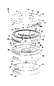
[0060] Referring now to FIGS. 11-14, a second embodiment of device for
storing and
preserving corneal graft tissue is shown. In one embodiment, the device is a
dual-chamber
vial. FIG. 11 shows a top perspective view of the second embodiment of an
assembled dual-
chamber vial, FIG. 12 shows an exploded view thereof, FIG. 13 shows a first
cross-sectional
view thereof, and FIG. 14 shows a second cross-sectional view thereof. The
second
embodiment of the dual-chamber vial 80 provides the same functionality as the
first
embodiment of the dual-chamber vial 10. However, in the second embodiment, the
dual-
chamber vial 80 is composed of four components that are removably couplable to
each other,
rather than three components (for example, as shown in FIG. 2). Further, in
one embodiment,
the second embodiment of the dual-chamber vial 80 includes locking elements
rather than
threading. However, in another embodiment, the second embodiment of the dual-
chamber
CA 03112767 2021-03-12
WO 2020/056392 17
PCT/US2019/051200
vial 80 includes threading as shown and described regarding the first
embodiment of the dual-
chamber vial 10 in FIGS. 1-8. These features of the second embodiment of the
dual-chamber
vial 80 may simplify manufacturing (for example, each of the four components
may be
formed by injection molding). Therefore, unless otherwise noted, reference in
FIGS. 11-15
to the same features of the first embodiment of the dual-chamber vial 10 of
FIGS. 1-10 will
be understood to have the same or substantially similar structure and/or
function and, to avoid
redundancy and complexity, will not be explained in detail regarding FIGS. 11-
15.
[0061] Continuing to refer to FIGS. 11-14, in one embodiment, the dual-
chamber vial 80
generally includes a longitudinal axis 82, a first lower or first portion 84,
a second lower or
second portion 86, an upper or third portion 88, and a lid 90. In one
embodiment, the first
portion 84 and the second portion 86, when coupled together, define a first
chamber 92 (for
example, similar to the first chamber 14 defined by the first portion 12 of
the first
embodiment of the dual-chamber vial 10). Further, when the dual-chamber vial
80 is
assembled, the second portion 86, the third portion 88, and the lid 90
together define a second
chamber 94 (for example, similar to the second chamber 18 defined by the
second portion 16,
the lid 20, and the corneal graft tissue support structure 26 of the first
portion 12 of the first
embodiment of the dual-chamber vial 10). Further, when the corneal graft
tissue is retained
within the dual-chamber vial 80, the corneal graft tissue 60 may also define
at least a portion
of the second chamber 94, as the corneal graft tissue 60 prevents the second
preservation
medium 68 from passing through the aperture 112 of the corneal graft tissue
support structure
110 and entering the first chamber 92. As noted above, in one embodiment the
first and
second portions 84 and 86 together are structurally analogous to the first
portion 12 of the
first embodiment of the dual-chamber vial 10 of FIGS. 1-8, the third portion
88 is structurally
analogous to the second portion 16 of the first embodiment of the dual-chamber
vial 10 of
FIGS. 1-8, and the lid 90 is structurally analogous to the lid 20 of the first
embodiment of the
dual-chamber vial 10 of FIGS. 1-8. Thus, the dual-chamber vial 80 is generally
composed of
three components 84, 86, and 88 that are removably couplable to each other.
[0062] In one embodiment, the dual-chamber vial 80 has a generally
cylindrical shape,
with flat or at least substantially flat ends (or at least a portion of each
end is flat, allowing the
dual-chamber vial 80 to securely stand or rest on a flat surface) and a round
cross-sectional
shape. In this configuration, one end of the dual-chamber vial 80 may be set
on a flat surface
such that the first portion 84, second portion 86, third portion 88, and lid
90 are vertically
aligned with each other (as shown in FIG. 11). In one embodiment, each of the
first portion
84, the second portion 86, the third portion 88, and the lid 90 have the same
or substantially
CA 03112767 2021-03-12
WO 2020/056392 18
PCT/US2019/051200
the same outer diameter, so the assembled dual-chamber vial 80 is a continuous
or at least
substantially continuous outer diameter. However, it will be understood that
the assembled
dual-chamber vial 80, and/or components thereof, may have different sizes,
shapes, and
configurations than those shown and described herein. Further, in one
embodiment, the
material from which the dual-chamber vial 80, or at least the first portion 84
and the lid 90, is
composed is transparent and/or translucent to facilitate viewing of the
corneal graft tissue by
the naked eye, a microscope, and/or or other viewing device when the corneal
graft tissue is
within the dual-chamber vial 10. For simplicity, however, the dual-chamber
vial may appear
opaque in the figures to simplify depiction of its structure.
[0063] Continuing to refer to FIGS. 11-14, in one embodiment the components
of the
dual-chamber vial 80 are couplable to each other by complementary or matable
locking
members, rather than threading. In one embodiment, the first portion 84
includes at least one
tab 96A and the second portion 86 includes at least one slot 96B that is
complementary to the
at least one tab 96A of the first portion 84. Put another way, each of the at
least one tab 96A
of the first portion 84 functions as a male locking member and is matingly
received by
corresponding one of the at least one slot 96B in the second portion 86,
thereby securing the
first portion 84 and the second portion 86 together. Likewise, in one
embodiment, the second
portion 86 also includes at least one tab 98A and the third portion 88
includes at least one slot
98B, each of the at least one tab 98A being matingly received by a
corresponding one of the
at least one slot 98B. Still further, in one embodiment, the third portion 88
also includes at
least one tab 100A and the lid 90 includes at least one slot 100B, each of the
at least one tab
100A being matingly received by a corresponding one of the at least one slot
100B.
[0064] In one embodiment, each tab 96A, 98A, 100A is integrally formed
with its
corresponding portion 84, 86, 88 of the dual-chamber vial 80, although in
other embodiments
the tabs 96A, 98A, 100A may be coupled, adhered, or otherwise attached to the
portions 84,
86, 88. Further, it will be understood that the tabs 96A, 98A, 100A and/or the
slots 96B,
98B, 100B may be positioned around the circumference of the dual-chamber vial
80 at
locations other than those shown in the figures, provided the portions 84, 86,
88 can be
positioned relative to each other such that the tabs 96A, 98A, 100A and the
slots 96B, 98B,
100B can be engaged with one another to lock the portions together 84, 86, 88
when the dual-
chamber vial 80 is assembled.
[0065] As is best seen in FIG. 12, in one embodiment the first portion
84 generally
includes a base 102 and a wall 104 extending from and circumscribing the base
102, and the
at least one tab 96A protrudes from the wall 104. In one embodiment, the at
least one tab
CA 03112767 2021-03-12
WO 2020/056392 19
PCT/US2019/051200
96A includes two tabs 96A that are opposite each other (that is, positioned at
180 , or at least
180 5 from each other). In one embodiment, the base 102 provides a viewing
surface 103
through which the epithelial side of the corneal graft tissue 60 within the
dual-chamber vial
80 can be viewed.
[0066] As is best seen in FIG. 12, in one embodiment, the second portion 86
generally
includes a wall 106, a rim 108, a corneal graft tissue support structure 110
defining an
aperture 112, and an engagement rim 114 surrounding, or at least partially
surrounding (or, in
some embodiments, circumscribing) the aperture 112. In one embodiment, at
least a portion
of the rim 114 has a concave configuration that cradles or supports the
corneal graft tissue in
its normal concave configuration, with the epithelial side of the corneal
graft tissue facing the
first chamber 92 and the endothelial side of the corneal graft tissue facing
the second
chamber 94 when the dual-chamber vial 80 is assembled. In one embodiment, the
corneal
graft tissue support structure 110 is planar, or at least substantially
planar, and lies in a plane
that is orthogonal to, or at least substantially orthogonal to, the
longitudinal axis 82.
However, it will be understood that the corneal graft tissue support structure
110 may have
another shape, such as convex or concave. When the dual-chamber vial 80 is
assembled (or
at least when the first and second portions 84, 86 are coupled together), the
first portion 84
and the second portion 86 together define the first chamber 92.
[0067] Continuing to refer to FIG. 12, in one embodiment, the rim 108
has an outer
diameter that is less than the outer diameter of the wall 106 (that is, the
rim 108 is closer to
the longitudinal axis 82 than the wall 106), and each of the at least one tab
98A protrudes
from the wall of the rim 108 by a distance that is between approximately 50%
to
approximately 150% ( 10%) of the distance between the rim 108 and the wall
106.
However, it will be understood that the at least one tab 98A may protrude by a
distance that is
less than or greater than this range. In one embodiment, the at least one tab
98A protrudes
from the wall of the rim 108. In one embodiment, the at least one tab 98A
includes two tabs
98A that are opposite each other (that is, positioned at 180 , or at least 180
5 from each
other). Further, in one embodiment, the at least one slot 96B is defined by
the wall 106 and
includes two slots 96B that are opposite each other (that is, positioned at
180 , or at least
180 5 from each other) and vertically aligned with the tab(s) 98A. In one
embodiment,
the corneal graft tissue support structure 110 is flat or at least
substantially flat, although it
will be understood that the corneal graft tissue support structure 110 may
have another shape,
such as convex or concave. When the dual-chamber vial 80 is assembled (or at
least when
CA 03112767 2021-03-12
WO 2020/056392 20
PCT/US2019/051200
the first and second portions 84, 86 are coupled together), the first portion
84 and the second
portion 86 together define the first chamber 92.
[0068] As is best seen in FIG. 12, in one embodiment, the third portion
88 generally
includes an annular body portion 120 and a corneal graft tissue retainment
structure 122
extending between the inner surface 123 of the annular body portion 120. When
the dual-
chamber vial 80 is assembled, the corneal graft tissue support structure 110
and the corneal
graft tissue retainment structure 122 may together be referred to as the
corneal graft tissue
suspension assembly. In one embodiment, the annular body portion 120 extends
beyond (that
is, above when the dual-chamber vial 80 is assembled) the corneal graft tissue
retainment
structure 122, thereby at least partially defining the second chamber 94. In
one embodiment,
the corneal graft tissue retainment structure 122 is shaped substantially
similar to the corneal
graft tissue retainment structure 40 of FIGS. 1-8 and generally includes an
annular structure
124 defining a central aperture 126 and an engagement rim 128, and a plurality
of radial
spokes 130 extending between the annular structure 124 and the inner surface
123 of the
annular body portion 120. Thus, the central aperture 126 is within and coaxial
with the
annular body portion 120. In one embodiment, the annular body portion 120 also
includes an
annular groove 131 in the upper rim that is sized and configured to receive
and retain therein
a gasket (not shown) for ensuring or enhancing a fluid-tight seal between the
lid 90 and the
third portion 88. Similarly, one or more other portions of the dual-chamber
vial 80 may also
include a groove and gasket for ensuring or enhancing fluid-tight seals.
[0069] Continuing to refer to FIG. 12, in one embodiment, the annular
body portion 120
includes at least one release element 132 that at least partially defines the
at least one slot
98B. In one embodiment, each release element 132 includes a grip portion 134
that extends
away from the outer surface 135 of the annular body portion 120 (that is,
extends away from
the longitudinal axis 82), and the annular body portion 120 includes a slit
136 on either side
of the release element 132 that at least partially separate the release
element 132 from the
annular body portion 120 and allow the release element to move or flex
relative to the annular
body portion 120. For example, to uncouple the third portion 88 from the
second portion 86,
a user may engage the grip portion(s) 134 and lift or move the grip portion(s)
134 away from
the annular body portion 120 to disengage the tab(s) 98A of the second portion
86 from the
slot(s) 98B of the third portion 88. In one embodiment, the at least one tab
100A includes
two tabs 100A that are opposite each other (that is, positioned at 180 , or at
least
approximately 180 ( 5 ) from each other). Further, in one embodiment, the at
least one slot
98B includes two slots 98B that are opposite each other (that is, positioned
at 180 , or at least
CA 03112767 2021-03-12
WO 2020/056392 21
PCT/US2019/051200
approximately 180 ( 5 ) from each other) and positioned at 90 between the
tabs 100A.
Put another way, in one embodiment a first tab 100A is centered at
approximately 0 , a first
slot 98B is centered at approximately 90 , a second tab 100B is centered at
approximately
180 , and a second slot 09B is centered at approximately 270 relative to the
circumference
of the annular body portion 120. Further, in one embodiment, the slot(s) 98B
of the third
portion 88 are vertically aligned with the tab(s) 98A of the second portion 86
when the dual-
chamber vial 80 is assembled.
[0070] As is best seen in FIG. 12, in one embodiment the lid 90
generally includes a face
138 surface and at least one release element 140. In one embodiment, the at
least one release
element 140 includes two release elements 140, and each release element 140
defines a slot
100B. In one embodiment, each release element 140 includes two arms 142 that
extend
downward from the outer surface of the lid 90 and that are coupled to or meet
with a grip
portion 144 that extends that extends away from the outer surface 143 of the
lid 90 (that is,
extends away from the longitudinal axis 82). The outer surface of the 143 lid
90, the arms
142, and the grip portion 144 together define a slot 100B. In one embodiment,
the slots 100B
are opposite each other (that is, positioned at 180 , or at least
approximately 180 ( 5 ) from
each other) and are vertically aligned with the tabs 100A of the third portion
88 when the
dual-chamber vial 80 is assembled. In one embodiment, the face 138 includes an
indentation
146 that extends from the face 138 and into the dual-chamber vial 80 toward
the third portion
88 (for example, downward when the dual-chamber vial 80 is assembled).
Further, when the
dual-chamber vial 80 is assembled, the second portion 86, the third portion
88, and the lid 90
together define a second chamber 94, with the indentation 146 at least
partially defining the
roof or upper surface of the second chamber 94 and providing a viewing surface
148 through
which the endothelial side of the corneal graft tissue within the dual-chamber
vial 80 can be
viewed. Optionally, the face 138 also includes one or more indicia 150 (for
example, arrows
as shown in FIG. 11-14) that indicate to a user where the release element(s)
140 are for
removal of the lid 90. For example, the user may manipulate the grip portion
144 of each
release element 140 of the lid 90 to remove the lid 90 in a similar manner as
described above
for uncoupling the second portion 86 and the third portion 88. In one
embodiment, neither
the first portion 84 nor the second portion 86 includes release elements, to
reduce the
likelihood of user uncoupling the first and second portions 84, 86 and
unintentionally spilling
the first preservation medium 64 from the first chamber 92. Conversely, the
lid 90 is easily
removed for viewing the corneal graft tissue more closely and/or for replacing
the second
CA 03112767 2021-03-12
WO 2020/056392 22
PCT/US2019/051200
preservation medium 68, and the second and third portions 86, 88 are easily
uncoupled from
each other to release the corneal graft tissue 60 for use.
[0071] Referring again to FIGS. 11-14, and with reference to FIG. 9, the
corneal graft
tissue suspension assembly generally lies in a plane that is orthogonal to, or
at least
substantially orthogonal to, the longitudinal axis 82 of the dual-chamber vial
80 (put another
way, in one embodiment the corneal graft tissue suspension assembly is
configured to support
the corneal graft tissue generally in a plane that bisects the dual-chamber
vial 80 into a lower
chamber 92 and an upper chamber 94). In one embodiment, the corneal graft
tissue
suspension assembly generally includes a first element, which includes at
least the corneal
graft tissue support structure 110, and a second element, which includes at
least the corneal
graft tissue retainment structure 122, and the first and second elements are
configured to be
vertically and horizontally aligned when the dual-chamber vial 80 is
assembled. Further, in
one embodiment there is a gap of between approximately 0.25 mm ( 0.05 mm) and
approximately 0.85 mm ( 0.05 mm) between at least a portion of the first
element and at
least a portion of the second element (for example, between the engagement
rims 114 and
128), such that when the dual-chamber vial 80 is assembled and contains a
corneal graft
tissue, the corneal graft tissue is suspended between, and may be in contact
with each of, the
corneal graft tissue support structure 110 of the second portion 86 and the
corneal graft tissue
retainment structure 122 of the third portion 88. In particular, the
epithelial side of the
corneal graft tissue rests on the corneal graft tissue support structure 110
such that at least a
portion of the epithelial side is exposed through the aperture 112 to the
first preservation
medium 64 within the first chamber 92 and at least a portion of the epithelial
side is in
contact with the engagement rim 114 surrounding the aperture 112. Further,
when the dual-
chamber vial 80 is assembled, the engagement rim 128 of the annular structure
124 of the
corneal graft tissue retainment structure 122 circumscribes, but is not in
contact with, the
endothelial side of the cornea, but is in contact with (or closely proximate)
the sclera (for
example, the endothelial side of the sclera), as shown in FIG. 9. Although
reference numbers
associated with the first embodiment of the dual-chamber vial 10 are shown in
FIG. 9, it will
be understood that corresponding portions of the second embodiment of the dual-
chamber
.. vial 80 may be positioned in a like manner relative to corneal graft tissue
when the dual-
chamber vial 80 is assembled.
[0072] Referring now to FIGS. 13 and 14, cross-sectional views of the
dual-chamber vial
80 are shown. The wall 104 of the first portion 84 has an outer diameter and
the wall 106 of
the second portion 84 has an inner diameter. In one embodiment, the outer
diameter of the
CA 03112767 2021-03-12
WO 2020/056392 23
PCT/US2019/051200
wall 104 is slightly less than the inner diameter of the wall 106, such that
the second portion
86 is sized and configured to receive and retain therein the first portion 84,
and the first
portion 84 fits in close tolerance within the second portion 86. In one non-
limiting example,
the inner diameter of the wall 106 may be up to 0.015 mm larger than (and not
the same as or
smaller than) the outer diameter of the wall 104. Further, in one embodiment,
the first
portion 84 is received within the second portion 86 such that the base 102 of
the first portion
84 forms the base of the dual-chamber vial 80, but the wall 104 of the first
portion 84 is not
visible when the dual-chamber vial 80 is assembled. Likewise, the rim 108 of
the second
portion 86 has an outer diameter and at least a portion of the annular body
portion 120 has an
.. inner diameter that is slightly greater than the outer diameter of the rim
108 such that the
third portion 88 is sized and configured to receive and retain therein at
least the rim of the
second portion 86. Finally, the lid 90 has an outer diameter and the annular
body portion 120
has an outer diameter that, in one embodiment, is the same or approximately
the same as the
outer diameter of the lid 90. Thus, when the dual-chamber vial 80 is
assembled, the dual-
chamber vial 80 may have at least substantially continuous outer diameter from
the base 102
to the lid 90.
[0073] In an alternative embodiment of the dual-chamber vial 80, the
dual-chamber vial
80 includes threading for coupling the first, second, and third components 84,
86, 88 and the
lid 90 together instead of or in addition to the tabs 96A, 98A, 100A and slots
96B, 98B, 100B
as shown and described herein and in FIGS. 11-14. For example, in one
embodiment, the
first portion 84 includes a first threading on an outer surface of the wall
104; the second
portion 86 includes a second threading on an inner surface of the wall 106
that is matably
couplable to the first threading, as well as a third threading on an outer
surface of the rim
108; the third portion 88 includes a fourth threading on an inner surface of,
or on a surface
within (such as within a groove), the annular body portion 120 that is matably
couplable to
the third threading, as well as a fifth threading on an inner or outer surface
of the annular
body portion 120; and the lid 90 includes a sixth threading on an inner or
outer surface of the
lid that is matably couplable to the fifth threading. Thus, the first and
second portions 84, 86
may be screwed together, the second and third portions 86, 88 may be screwed
together, and
.. the third portion 88 and the lid 90 may be screwed together to assemble the
dual-chamber vial
80. Further, the threadings may be used as coupling means in addition to or
instead of the
tabs and slots.
[0074] Referring now to FIG. 15, a flow chart of an exemplary method for
storing and
preserving corneal graft tissue 60 within the dual-chamber vial 80 is shown.
In a first step
CA 03112767 2021-03-12
WO 2020/056392 24
PCT/US2019/051200
160, the first portion 84 and the second portion 86 are coupled together to
create the first
chamber. As noted above, the second portion 86 includes the corneal graft
tissue support
structure 110 having an aperture 112. In one embodiment, the tab(s) 96A are
aligned with
slot(s) 96B and the second portion 86 is pressed downward onto or over the
first portion 84
until each tab 96A at least partially extends into its corresponding slot 96B,
thereby
preventing the first and second portions 84, 86 from being pulled apart. For
example, the
dual-chamber vial 80 may be sold to a user with the first and second portions
84, 86 already
coupled together, but with each of the third portion 88 and the lid 90 being
uncoupled from
any other component. Alternatively, the dual-chamber vial 80 may be sold to a
user in a
completely disassembled or uncoupled state. In a second step 162, the first
preservation
medium 64 (or mixture of media) is added to the first chamber 92, such as
through the
aperture 112 in the corneal graft tissue support structure 110, until the
level of the first
preservation medium 64 is level with or immediately proximate the aperture
112.
[0075] Continuing to refer to FIG. 15, in a third step 164, corneal
graft tissue 60 is placed
on the corneal graft tissue support structure 110 such that at least a portion
of the epithelium
62 (for example, the sclera 67) is in contact with an upper surface of the
engagement rim 114
of the corneal graft tissue support structure 110 and at least a portion of
the epithelium 62 (for
example, the corneal epithelium 69) is in contact with the first preservation
medium 64
through the aperture 112. In a fourth step 166, once the corneal graft tissue
60 is in place, the
third portion 88 is coupled to the second portion 86, such as by the method
discussed above
in the first step 160. For example, the tab(s) 98A are aligned with slot(s)
98B and the third
portion 88 is pressed downward onto the second portion 86 until each tab 98A
at least
partially extends into its corresponding slot 98B, thereby preventing the
second and third
portions 86, 88 from being pulled apart. Further, when the third portion 88 is
coupled to the
first portion 86, the engagement rim 128 of the annular structure 124 may be
in contact with
the endothelial side 66 of the sclera 67, but not the endothelial side 66 of
the cornea 69.
Thus, the corneal graft tissue 60 is suspended, retained, or otherwise engaged
within the dual-
chamber vial 80 between the corneal graft tissue support structure 110 and the
corneal graft
tissue retainment structure 122, and further movement (for example, "sloshing"
within the
dual-chamber vial 10) of the corneal graft tissue is prevented. Likewise, in
some
embodiments the corneal graft tissue 60 blocks at least the apertures 112 and
126 to form a
fluid-tight seal between the second portion 86 and the third portion 88 and
fluidly isolate the
first chamber 92 from the second chamber 94.
CA 03112767 2021-03-12
WO 2020/056392 25
PCT/US2019/051200
[0076] Continuing to refer to FIG. 15, in a fifth step 168, a second
preservation medium
68 (or mixture of media) is added to the second chamber 94, or the portion of
the second
chamber 94 defined by the third portion 88. In one embodiment, the second
preservation
medium 68 flows downward through the apertures (central aperture 126 and
apertures
defined between the radial spokes 130) in the corneal graft tissue retainment
structure 122 to
come into contact with the endothelium 66 of the corneal graft tissue 60, but
is prevented
from flowing past the corneal graft tissue 60 and into the first chamber 92 or
otherwise
contacting the epithelium 62 of the corneal graft tissue 60. In a sixth step
170, the lid 90 is
coupled to the third portion 88, such as by the method discussed above in the
first step 160.
For example, the tab(s) 100A are aligned with slot(s) 100B and the lid 90 is
pressed
downward onto the third portion 88 until each tab 100A at least partially
extends into its
corresponding slot 100B, thereby preventing the third portion 88 and the lid
90 from being
pulled apart. After this step 170, the dual-chamber vial 80 is fully assembled
and fluidly
sealed, with the corneal graft tissue 60 safely within. The dual-chamber vial
80 may then be
transported and/or stored using any suitable conditions. Further, the
epithelial side 62 and/or
the endothelial side 66 of the corneal graft tissue 60 may be visualized
through the dual-
chamber vial 80 (for example, through one or both of the viewing surfaces 103,
148) with the
naked eye and/or a viewing device. To remove the corneal graft tissue 60 from
the dual-
chamber vial 80, the lid 90 is uncoupled from the third portion 88, the second
preservation
medium 68 removed or poured out, and then the third portion 88 is uncoupled
from the
second portion 86 and the exposed corneal graft tissue 60 may be removed and
used.
[0077] Embodiments
[0078] In one embodiment, a device (10, 80) for preserving corneal graft
tissue comprises:
a first chamber (14, 92); a second chamber (18, 94); and a corneal graft
tissue suspension
assembly (61) that is configured to retain and suspend the corneal graft
tissue between the
first chamber (14, 92) and the second chamber (18, 94), the first chamber (14,
92) being
fluidly isolated from the second chamber (18, 94) when the corneal graft
tissue is retained
and suspended within the corneal graft tissue suspension assembly.
[0079] In one aspect of the embodiment, the corneal graft tissue
suspension assembly
includes: a first element; and a second element, the first element and the
second element
being vertically and horizontally aligned with each other when the device (10,
80) is
assembled. In one aspect of the embodiment, the device (10, 80) includes a gap
between the
first element and the second element when the device (10, 80) is assembled. In
one aspect of
the embodiment, the gap is between approximately 0.25 mm and approximately
0.85 mm.
CA 03112767 2021-03-12
WO 2020/056392 26
PCT/US2019/051200
[0080] In one aspect of the embodiment, each of the first element and
the second element
have a convex configuration.
[0081] In one aspect of the embodiment, the device (10) further
comprises: a first portion
(12), at least a portion of the first portion (12) defining the first chamber
(14); and a second
portion (16), at least a portion of the second portion (16) defining the
second chamber (18),
the second portion (16) being removably couplable to the first portion (12).
In one aspect of
the embodiment, the first portion (12) defines the first element of the
corneal graft tissue
suspension assembly (61), the first portion (12) and the first element
defining the first
chamber (14). In one aspect of the embodiment, the first element of the
corneal graft tissue
suspension assembly (61) includes an aperture (30) located in the center of
the first element.
[0082] In one aspect of the embodiment, the second portion (16) of the
device (10) defines
the second element of the corneal graft tissue suspension assembly (61). In
one aspect of the
embodiment, the second portion (16) of the device (10) includes an annular
body portion
(34), the second element of the corneal graft suspension assembly (61) having:
an annular
structure (44) defining a central aperture (46); and a plurality of radial
spokes (48) extending
between the annular structure (44) and the annular body portion (34), the
annular body
portion (34) and the second element partially defining the second chamber
(18).
[0083] In one aspect of the embodiment, the device (10) further
comprises a lid (20), the
lid (20) being removably couplable to the second portion (16) of the device
(10). In one
aspect of the embodiment, the annular body portion (34), the second element,
and the lid (20)
together define the second chamber (18).
[0084] In one embodiment, a device (10) for preserving corneal graft
tissue (60), the
corneal graft tissue (60) having an endothelial side (66) and an epithelial
side (62),
comprises: a first portion (12), the first portion (12) including: a corneal
graft tissue support
structure (26) defining an aperture (30); and a first chamber (14) within the
first portion (12),
the first chamber (14) being at least partially defined by the corneal graft
tissue support
structure (26); a second portion (16), the second portion (16) including: a
corneal graft tissue
retainment structure (40); and a second chamber (18) at least partially within
the second
portion (16), the second chamber (18) being at least partially defined by the
corneal graft
.. tissue retainment structure (40); and a lid (20), the second chamber (18)
being at least
partially defined by the lid (20), the second portion (16) being removably
coupled to the first
portion (12) and the lid (20) being removably coupled to the second portion
(16) when the
device (10) is assembled, and the corneal graft tissue support structure (26)
and the corneal
graft tissue retainment structure (40) being configured to suspend the corneal
graft tissue (60)
CA 03112767 2021-03-12
WO 2020/056392 27
PCT/US2019/051200
between the first chamber (14) and the second chamber (18) when the device
(10) is
assembled.
[0085] In one aspect of the embodiment, the corneal graft tissue support
structure (26) and
the corneal graft tissue retainment structure (40) are configured to suspend
the corneal graft
tissue (60) such that: at least a portion of the epithelial side (62) is in
contact with the corneal
graft tissue support structure (26); at least a portion of the epithelial side
(62) is in contact
with a first solution (64) within the first chamber (14); at least a portion
of the endothelial
side (66) is in contact with the corneal graft tissue retainment structure
(40); and at least a
portion of the endothelial (66) side is in contact with a second solution (68)
within the second
chamber (18). In one aspect of the embodiment, the first solution (64)
contains dextran and
the second solution (68) is a low-dextran or a dextran-free solution.
[0086] In one aspect of the embodiment, the first portion (12) includes
a first threading
(24) on an outer surface; the second portion (16) includes a second threading
(36) on an inner
surface and a third threading (38) on an outer surface; and the lid (20)
includes a fourth
threading (54) on an inner surface.
[0087] In one aspect of the embodiment, the lid (20) includes an
indentation (58) that
extends into the second chamber (18).
[0088] In one embodiment, a method of preserving corneal graft tissue
(60) within a vial
(10), the corneal graft tissue (60) having an endothelial side (66) and an
epithelial side (62)
opposite the endothelial side, comprises: filling a first chamber (14) of the
vial (10) with a
first medium (64); placing the corneal graft tissue (60) within a corneal
graft tissue
suspension assembly (61); and filling second chamber (18) of the vial (10)
with a second
medium (68), the corneal graft tissue suspension assembly (61) being located
between the
first chamber (14) and the second chamber (18).
[0089] In one aspect of the embodiment, the corneal graft tissue suspension
assembly (61)
includes a corneal graft tissue retainment element (40) and a corneal graft
tissue support
element (26) with an aperture (30), placing the corneal graft tissue (60)
within the corneal
graft tissue suspension assembly (61) including: placing the corneal graft
tissue (60) on the
corneal graft tissue support structure (26) such that at least a portion of
the epithelial layer
(62) is in contact with the first medium (64) through the aperture (30); and
placing the
corneal graft tissue retainment structure (40) over the corneal graft tissue
(60) and in contact
with the endothelial layer (66), the endothelial layer (66) being in contact
with the second
medium (68) when the second chamber (18) is filled with the second medium
(68).
CA 03112767 2021-03-12
WO 2020/056392 28
PCT/US2019/051200
[0090] In one aspect of the embodiment, the corneal graft tissue support
structure (26) is a
component of a first vial portion (12) and the corneal graft tissue retainment
structure (40) is
a component of a second vial portion (16), placing the corneal graft tissue
retainment
structure (40) over the corneal graft tissue (60) including coupling the first
vial portion (12)
and the second vial portion (16) together.
[0091] It will be appreciated by persons skilled in the art that the
present embodiments are
not limited to what has been particularly shown and described herein above. In
addition,
unless mention was made above to the contrary, it should be noted that all of
the
accompanying drawings are not to scale. A variety of modifications and
variations are
possible in light of the above teachings.