Note: Descriptions are shown in the official language in which they were submitted.
1
HEATING SYSTEM USING HEAT EXTRACTED FROM A COMPUTER
PROCESSING UNIT
This invention relates to an arrangement which includes a cooling tank
to extract and utilize heat from the operation of the computer processing to
maintain
the unit cool and to enable the heat to be transferred and utilized in a
separate heating
operation.
BACKGROUND OF THE INVENTION
Currently the conventional way of cooling computers, servers or mining
rigs is with air using high volume fans. This causes major problems with noise
and
dust control system equating to higher maintenance and set up costs.
It is known that many computer processing systems generate significant
quantities of heat so that cooling is required. Examples of immersive liquid
cooling
systems for computer processing are shown in US Patent 9504190 (Best) issued
to
Green Revolution Cooling Inc and other patents by the same patentee and by
Delphi
.. Technologies in USA Patent 7307841 (Berlin) and by Hardcore Computers Inc
in US
Patent 7403392 (Attlesey). However there have been no significantly successful
techniques by which the heat from computer processing systems can be used
effectively to provide heating to other structures or operations.
SUMMARY OF THE INVENTION
According to one definition of the invention there is provided a method
for heating comprising:
generating a stream of a heat transfer liquid;
Date Recue/Date Received 2021-03-23
2
passing the heat transfer liquid through a heat source so that the heat
source is able to apply heat to the heat transfer liquid;
passing the heat transfer liquid through one or more heat dissipating
loads to transfer heat from the heat transfer liquid to said one or more
loads;
providing in a tank a cooling liquid formed of a dielectric material;
the tank containing a plurality of computer processing units, each
comprising at least one computer processing board carrying electrical
components
which operates to carry out computer processing operations while generating
heat;
causing the cooling liquid to pass through the tank while causing cooling
of the computer processing units so that the liquid is heated while cooling
the computer
processing units so as generate a first stream of cool liquid upstream of the
heating
of the liquid and a second stream of heated liquid downstream of the heating;
circulating the cooling liquid from the second stream through a
refrigeration cycle heat pump to the first stream so that the heat pump
extracts heat
from the second stream to return to the first stream;
the heat pump transferring the extracted heat from the cooling liquid to
the heat transfer liquid so that the heat transfer liquid passes from an inlet
stream
entering the heat pump to an exit stream leaving the heat pump and so that the
heat
transfer liquid passes both through the heat source and the heat pump for
receiving
heat from both.
According to a second definition of the invention there is provided a
method for heating comprising:
Date Recue/Date Received 2021-03-23
3
generating a stream of a heat transfer liquid;
passing the heat transfer liquid through one or more heat dissipating
loads to transfer heat from the heat transfer liquid to said one or more
loads;
providing in a tank a cooling liquid formed of a dielectric material;
the tank containing a plurality of computer processing units, each
comprising at least one computer processing board carrying electrical
components
which operates to carry out computer processing operations while generating
heat;
causing the cooling liquid to pass through the tank while causing cooling
of the computer processing units so that the cooling liquid is heated while
cooling the
computer processing units so as generate a first stream of cool liquid
upstream of the
heating of the liquid and a second stream of heated liquid downstream of the
heating;
circulating the cooling liquid from the second stream through a heat
pump to the first stream so that the heat pump extracts heat from the second
stream
to return to the first stream;
the heat pump transferring the extracted heat from the cooling liquid to
the heat transfer liquid so that the heat transfer liquid passes from an inlet
stream
entering the heat pump to an exit stream leaving the heat pump;
wherein the temperature in the second stream of the cooling liquid is
less than 60 degrees C and the temperature in the exit stream of the heat
transfer
liquid is greater than 70 degrees C, preferably greater than 80 degrees C and
more
preferably of the order of or greater than 90 degrees C.
Date Recue/Date Received 2021-03-23
4
Preferably in one embodiment, the heat pump is uses CO2 as a
refrigerant as this has heat differences (Delta T) which are particularly
suitable for the
temperatures available and required in the above method.
Preferably in one embodiment, the temperature in the second stream of
the cooling liquid is less than 60 degrees C and the temperature in the exit
stream of
the heat transfer liquid is greater than 70 degrees C.
Preferably in one embodiment, the temperature in the second stream of
the cooling liquid is in the range 40 degrees C to 60 degrees C and the
temperature
in the exit stream of the heat transfer liquid is in the range 70 degrees C to
95 degrees
C and more preferably around or above 90 degrees C.
These temperatures allow the temperature in one or more of the heat
dissipating loads to be at least 90 degrees C. This has he advantage that such
loads
are typically designed to operate at this temperature so that any reduction in
the
temperature, while it may produce heating of the load, is often insufficient
to meet
design requirements.
Preferably in one embodiment, the temperature in the first stream of the
cooling liquid is less than 45 degrees C and the temperature in the inlet
stream of the
heat transfer liquid is greater than 50 degrees C.
Preferably in one embodiment, the temperature in the first stream of the
cooling liquid is in the range 20 degrees C to 45 degrees C and the
temperature in the
inlet stream of the heat transfer liquid is in the range 50 degrees C to 70
degrees C.
Date Recue/Date Received 2021-03-23
5
In one embodiment, the cooling liquid is circulated between the second
and first streams by a liquid pump. However other embodiments may operate only
by
convection currents.
In one embodiment, the heat pump is located inside the tank and
preferably within the cooling liquid. However in other arrangements the heat
pump
may be located outside the tank.
Preferably in one embodiment, the heat source comprises a boiler
typically of the type which uses a combustion heating system such as gas or
solid fuel
to provide the required heating. In this arrangement, the heat dissipating
loads and
the boiler form an existing installation where the boiler and the loads such
as radiators,
heating elements and the like are designed to meet heating requirements at the
set
boiler temperature typically of the order of 90 degrees C. In this case, the
tank, the
cooling liquid, the plurality of computer processing units and heat pump are
added to
the existing installation as a supplementary heat source so that the heat from
the
computer processing is used as a further heat source which can be used as an
alternative to the boiler or in replacement for heat from the boiler. In this
arrangement
the computer processing can become the main or primary heat source and the
existing
boiler can be used to supplement if the primary source cannot keep or as a
replacement if the primary source is inactive for any reason.
Preferably in one embodiment, the cooling liquid is a vegetable oil such
as soy bean or canola oil.
Date Recue/Date Received 2021-03-23
6
The arrangement herein there provides a solution to enhance both sides
of the heating and cooling arrangement where the liquid to liquid (Oil to
Glycol/water)
loop is replaced with a CO2 Heat Pump (refrigeration cycle or compression
type).
These new more efficient environmentally friendly heat pumps utilize the hot
temperature output of the tank at around 50C (112F) and bump it up to 90C
(190F).
The return loop (Cool side) of the heat pump is then reduced back to 25-30C
and is
better able to absorb the heat from the cooling tank.
This acts to solve the difficulty of being able to tie into existing high
temperature boiler systems that typically operate at 180-190F. A major
restriction we
are seeing at the moment.... And allow us to operate very efficiently during
warmer
months in terms of cooling our tank without massive dry coolers to expel the
heat.
Would also allow use to use this set up in large commercial/industrial
applications.
In this way the excess heat can be extracted and transferred to a heat
exchanger which enables the extracted heat to be used in many different areas
including but not limited to:
Commercial/Industrial in-floor or geo thermal hydronic heating systems
Greenhouses
Agricultural barns ¨ Hog, Poultry and Dairy
Heating hot water in larger industrial application ¨ Car/truck washes
Residential heating
Grain drying
Cannabis drying / Dehydration systems
Date Recue/Date Received 2021-03-23
7
Low temperature evaporation systems
Cannabis industry including heating and low temperature dehydrating
Aquaculture installation to heat water
Underground mining operations ¨ heating mine shafts
Large swimming pools
The arrangement herein provides a unique arrangement for space
heating which uses computing chips as replacement of conventional heating
elements
creating a modulating resistive load heater. The idea is to utilize lower cost
commercial
electricity rates as well a as a 100% renewable energy provided by electric
utilities
particularly hydro based utilities to do two functions: the first to provide
space heating
and second to provide a means of cooling for the intense revenue generating
computing such as mining crypto currencies or similar data processing.
In recent years with the development of Blockchain technology, it has
now become evident that this new method of computing will allow for more
decentralized computing and would offer greater potential to install more
robust and
redundant data processing system simultaneously giving the ability to
capitalize on all
the heat generated.
This invention offers a solution for space heating especially in countries
where the climate is colder. For example, many northern communities don't have
access to natural gas and are typically heating with electric boilers and or
fossil fuel
boilers. This invention will allow for an easy "Quick Connect" option to
efficiently
integrate to an existing hydronic system. The boiler systems can be installed
as
Date Recue/Date Received 2021-03-23
8
individual units or as a module containing multiple boilers to achieve the
desired heat
output. The boiler design can be customized to any size with a large range,
from 20
KW single tank to a 400+ KW system. The tank design is such that it can be
installed
in either a standalone installation inside existing infrastructure or
installed housed in
a containerized module.
The arrangement herein can preferably be used with a specific design
of the tank using a method for computer processing comprising:
providing in a tank a cooling liquid formed of a dielectric material;
the tank containing a plurality of computer processing units, each
comprising:
an exterior housing having a bottom opening at a bottom end and
a top opening at a top end and defining a closed peripheral wall between the
top and
bottom ends;
at least one computer processing board carrying electrical
components mounted within the housing which operates to carry out computer
processing operations while generating heat;
the tank having a dividing sheet in the tank dividing the tank into a bottom
manifold below the dividing sheet and a main portion of the tank above the
sheet;
the exterior housing of each computer processing unit being mounted
on the sheet with the bottom opening located at the sheet and the peripheral
wall
upstanding within the tank to the top end which spaced from the dividing
sheet;
Date Recue/Date Received 2021-03-23
9
a plurality of liquid transfer opening arrangements in the sheet where
each opening arrangement is associated with a respective one of the housings
to
allow liquid from the manifold to enter the housing and pass through the
opening;
introducing the cooling liquid into the manifold;
arranging a top surface of the liquid within the tank at a location which
is above the top end of the exterior housings;
causing the liquid to enter through the opening arrangements into the
exterior housings and to rise within the housings by convection caused by the
heat
within the housings and to exit from the housings through the top end into the
tank;
the liquid exiting from the top ends of the housings forming a heated
layer in the tank between the surface and the top ends;
extracting liquid from the layer;
and extracting heat from the extracted liquid to create a heat supply and
to return cooled liquid to the manifold.
Preferably the top ends lie in a common plane defining a bottom of the
layer to improve the stratification of the liquid in the layer as the hottest
area of the
tank to be tapped off. This zone depth can also be adjusted to accommodate
various
working fluid temperatures. The thicker the layer the hotter the fluid.
Typically the extracted liquid is returned to the manifold by a pump which
is arranged to create a slight positive pressure such that the liquid is
caused to flow
through the housings substantially wholly by the convection rather than as a
positive
flow. This again improves the stratification of the liquid. No liquid enters
the quiescent
Date Recue/Date Received 2021-03-23
10
zones between the tubular housings so that this area again allows the heat to
concentrate in the stratified heated zone at the top of the tubular housings.
The
housings are preferably wholly open at the top and bottom so that the
peripheral wall
is fully open at each end as this creates the required flow through the
housings.
That is in one embodiment, the openings from the manifold through the
divider sheet are located at the housings such that the liquid only enters the
housings
and not between the housings to form the quiescent zone.
In one embodiment, the openings each provide an array which is shaped
to match the interior shape of the housing to generate a smooth flow rising in
the
housings so that for example the housings are rectangular in cross-section and
the
array is also rectangular and approximately matches the inside surface of the
housing.
For example, the array is formed by a series of parallel slots having a length
approximately equal to the dimension across the housing but an array of other
holes
can be used.
In one embodiment, the tank is dimensioned so that it contains the
housings arranged in rows and columns.
In one embodiment, the liquid is extracted through an opening at one
side of the tank which can be provided as a single opening communicating to a
single
duct feeding to a separate heat exchanger.
Preferably the opening is arranged at a height above the top ends and
below the top surface so as to extract only from the layer.
Date Recue/Date Received 2021-03-23
11
Preferably the liquid is a mineral oil, vegetable oil based or in some
cases a fully synthetic dielectric fluid can be used.
Preferably the liquid has the one or more of the following characteristics:
---Density: Near or in the range of 0.92 g/m3 (7.667 lbs/gal)
---Kinematic Viscosity: Near or in the range of 33-35 mm2/s g 40 C or
near or in the range of 15 cSt g 70 C
---Dielectric Breakdown: 2mm [kV] 35 (ASTM D6871)
---Boiling point: 360 C
---Flash point: 265 C (Closed Cup)
---Auto/self-ignition temperature: 401-404 C (ASTM E659)
---Vapor Pressure: Near or in the range 0 PA g 200 C
---Thermal Conductivity: Near or in the range of 0.15089 W/mK g 70 C
---Specific Heat: Near or in the range of 2.3472 kJ/kgK g 70 C
Preferably the dielectric liquid is selected with the characteristics to
cause very intense stratified temperature zone due to the inherent thermal
insulating
properties.
Preferably the dielectric liquid has properties that allow: a maximum heat
transfer, a high working fluid temperature (above 60 degrees C) and an
efficient heat
transfer.
Preferably the flow of liquid into the manifold and through the housings
is arranged such that the temperature in the layer is in the range 10 to 60 C.
Date Recue/Date Received 2021-03-23
12
Preferably the flow of liquid into the manifold and through the housings
is arranged such that the temperature returned to the manifold is in the range
30-85 C.
Preferably each computer processing unit is associated with an adjacent
power supply which is contained within the tank alongside the associated
housing
where the power supply is located in and cooled by the liquid between the
housings
without any flow from the manifold.
Preferably the computer processing units are dropped out when a peak
demand situation occurs.
Preferably the computer processing units are connected to utility smart
meters to aid in peak demand management.
Preferably there is provided a U-shaped holder mounted on the sheet
and arranged to hold the housing and the power supply supported upright.
Preferably the tank has a head zone that also acts as an expansion area
to accommodate fluid level fluctuations. This head zone should be kept free
from any
moisture and should be equipped to filter out particulate matter as well as
moisture.
Preferably the tank is completely sealed and vapour tight. The
installation of a pressure relief check valve set at 1-2 PSI is installed to
prevent any
over pressures causing damage.
Preferably the computing rigs or processors used are able to be
immersed without any modifications other than removing or disabling any fans
installed. All the air cooling arrangements or fines can be left intact.
Date Recue/Date Received 2021-03-23
13
The idea was to develop a very simple cost-effective tank system to cool
the computing rigs or chips using a dielectric fluids with certain properties
that allow:
a maximum heat transfer, a high working fluid temperature (above 60 degrees C)
and
an efficient heat transfer. There are minimal to no moving parts in the tank.
The result
.. is a design that operates with only one small circulating pump that uses
approximately
300 watts of power to pump the working fluid (Dielectric Fluid) through a heat
exchanger.
In order to achieve a system with no moving or overly complex parts, the
key was to try and minimize modifications required to conventional air-cooled
computing rigs including utilizing the factory made aluminum bodies and power
supplies. We designed a special holder where the CPU aluminum chassis or body
is
supported upright (Vertically) as well as the power supply to power each unit.
Another aspect of the tank design is the baffle plate to allow the cool
working fluid to collect in the "Cool Zone" of the tank under the baffle plate
where the
circulating pump will create a slight positive pressure. The baffle plate has
a number
of precision cut slots that direct the fluid into each computing rig housings
or "tubes".
The amount and sizes of the slots is determined based on the viscosity of the
fluid
and the maximum temperature allowable before any damage can occur to the
computing chips. This is typically maximum of 85 degree C). The housings or
"tubes"
act a chimney and can be customized to accommodate any type of computing
mother
boards.
Date Recue/Date Received 2021-03-23
14
The combination of having the cool stream of working fluid pass through
the baffle plates slots and directed into the aluminum mining rig bodies or
tubes give
a very strong thermal dynamic pumping action or chimney effect. This effect
help to
efficiently move the cooler working fluid from under the baffle plate through
the tube
structure, passed the computing boards including processing chips and carry
away
the intense heat generated.
Upon exiting the mining rig body or tube, the hot working fluid collects at
the top of the tank area or "Hot Zone". Another interesting part of this
invention is that
we are able to efficiently remove the hot working fluid with only one port
reducing
complicated baffles designs and costly manifold systems. We use the natural
tendencies of the dielectric fluid to cause very intense stratified
temperature zone due
to the inherent thermal insulating properties.
The design also allows the power supply which is suspended higher on
the holder to use the "Neutral Zone" temperature to cool the power supplies
(See
drawings). The power supplies do not generate as much heat as the main
computing
boards or chips so less working fluid is required to circulate through the
unit.
The system is designed to be fully modulating and remote controlled
interface for isolated operations including northern regions of Canada and US.
It can
also be coupled to utility smart meters to aid in peak demand management. The
systems can be designed to drop out when a peak demand situation occurs.
The current tank design can be suited from a residential setting to large
industrial.
Date Recue/Date Received 2021-03-23
15
BRIEF DESCRIPTION OF THE DRAWINGS
One embodiment of the invention will now be described in conjunction
with the accompanying drawings in which:
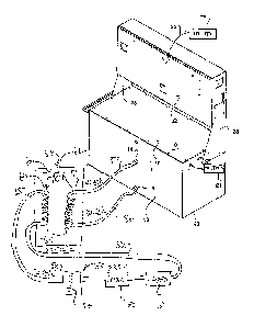
Figure 1 is an isometric view of one embodiment of the complete
apparatus including the cooling tank, heat exchanger, heating load, electrical
connections and connection to the power utility according to the present
invention.
Figure 2 is an isometric view of a processing unit and power supply
mounted on a mounting bracket for mounting inside the tank of Figure 1.
Figure 3 is s side elevational view of the processing unit and power
supply and bracket of Figure 2.
Figure 4 is s top plan view of the processing unit and power supply and
bracket of Figure 2.
Figure 5 is a cross-sectional view along the lines 5-5 of Figure 1 showing
the interior of the tank.
Figure 6 is a cross-sectional view along the lines 6-6 of Figure 4 showing
the passage of liquid through the plate to the interior of the tubular
housing.
Figure 7 is an isometric view of a further embodiment of the complete
apparatus including the cooling tank, heating load, electrical connections and
connection to the power utility which uses a refrigeration cycle type heat
pump to
generate specific temperatures for the heating system according to the present
invention.
Date Recue/Date Received 2021-03-23
16
In the drawings like characters of reference indicate corresponding parts
in the different figures.
DETAILED DESCRIPTION
The arrangement here in provides a tank 10 containing a cooing liquid
11 for cooling a plurality of circuit boards 12 and transferring the heat
therefrom to a
load 13. The cooling liquid 11 is extracted from the tank through a discharge
opening
14, passed through a heat exchanger 16 and returned to the tank through a
return 15.
A pump 17 is provided in the circuit through the heat exchanger to cause a
flow in the
liquid and to generate a low pressure at the return 15.
The tank comprises a rectangular body with four upstanding sides 18, a
top cover 19 and a base 20. This forms a closed container where the tank has a
head
zone above the level 11A of the liquid and below the top 19 that also acts as
an
expansion area to accommodate fluid level fluctuations. The head zone is kept
free
from any moisture by an extraction and a filter system 21 to filter out any
particulate
material from the liquid as well as any moisture. The tank is thus sealed and
vapour
tight.
The liquid in the tank filling the area between the base 20 and the top
level 11A acts as a cooling liquid which is formed of a suitable dielectric
material
having the characteristics defined above.
The tank carries a superstructure 22 mounted on end brackets 23 which
connect the superstructure to the ends of the tank. The superstructure
provides a
rectangular housing which contains the electronics necessary to control the
operation
Date Recue/Date Received 2021-03-23
17
of the circuit boards and the communications necessary to operate the system.
This
includes a communication system 24 for communication with the power utility 25
supplying the necessary power to the processing system.
The tank 10 contains a plurality of computer processing units 30
arranged in an array of rows and columns in the tank. Each unit 30 includes an
exterior
tubular housing 31 defined by four rectangular sides 32 extending from a
bottom face
33 to a top face 34. The top and bottom faces are generally open so that the
housing
forms a tubular duct through which the liquid can pas freely from the bottom
face to
the top face. The housing is a conventional housing structure which is
supplied by
many computer processing suppliers and typically the processing boards 12
within the
housing are cooled by air flow generated by a fan on one or both ends of the
housing.
The fans are removed so that the existing housing containing the existing
boards are
now cooled by the liquid. The housing thus defines a bottom opening at a
bottom
end and a top opening at a top end and a closed peripheral wall between the
top and
bottom ends.
The computer processing boards carrying electrical components
mounted within the housing are arranged as parallel boards at spaced positions
across the housing. These operate to carry out computer processing operations
in
conventional manner while generating heat. As is well known the amount of
processing power required for various high processing operations generates
high
levels of heat which must be removed and which are sufficient for significant
amount
of space heating particularly in cold weather areas.
Date Recue/Date Received 2021-03-23
18
Each computer processing unit is associated with an adjacent power
supply 35 in the form of a generally rectangular body containing convention
components for the processing unit 30. There is provided an L-shaped holder
bracket
36 mounted on the sheet and arranged to hold the housing and the power supply
supported upright. The bracket includes a horizontal base plate 37 which
extends
across the bottom end 33 of the housing 31. An upstanding plate 38 connected
to the
base at an apex 36A carries the power supply on an inner face of the plate so
that it
is located adjacent the housing 31 and both are held generally parallel and
slightly
spaced. A connector 35A extends from the poser supply through the tank to an
exit
gland (not shown) to the control system in the superstructure.
The bracket 36 has in the base 37 and opening 37A which exposes the
bottom end 12A of the boards 12 for entry of the cooling liquid through the
base 37
into the tubular housing 31. The opening is generally rectangular so that the
edges
37C are parallel to the side walls 32. However triangular flanges 37B are
located at
the corners for attachment of similar shaped flanges at the bottom end 33 to
be
attached to the base 37. Thus the housing 31 and the boards 12 therein is
attached
to the base 37 and the power supply 35 is attached to the plate 38 enabling
both to
be mounted in the rows and columns shown in Figure 5 within the tank.
The rectangular tank has a dividing sheet 40 in the tank 10 parallel to
the base 20 dividing the tank into a bottom manifold 41 below the dividing
sheet 40
and above the base 20 and a main portion of the tank 42 above the sheet 40.
Date Recue/Date Received 2021-03-23
19
The brackets 36 are fastened to the bottom sheet 40 in the rows and
columns so that the exterior housing 31 of each computer processing unit is
mounted
on the sheet 40 with an opening at the bottom end 33 located at the sheet 40
and the
peripheral wall 32 upstanding within the tank to the top end 34 which spaced
from the
dividing sheet 40.
In order for the cooling liquid to pass from the manifold 41 into each
housing 32, a plurality of liquid transfer opening arrangements 44 are
provided in the
sheet where each opening arrangement 44 is associated with a respective one of
the
housings 31 to allow liquid from the manifold 41 to enter the housing 31 and
pass
through the opening 37A into the housing. The liquid enters the manifold
through the
return 15 and spreads in the manifold so the opening arrangements 44 for
passage
into the housings. The opening arrangements 44 as shown include a row of
parallel
spaced slots 44A, 44B and 44C which form an area generally matching the area
of
the opening 37A so that the slots are of a length matching the width of the
housing
31.
The depth of the liquid is arranged so that the top surface11A of the
liquid within the tank is at a position below the top wall 19 at a location
and which is
above the top end 35 of the exterior housings 31.
The liquid thus acts to enter through the opening arrangements 44 into
the exterior housings and each provides an array which is shaped to match the
interior
shape of the housing to generate a smooth flow rising in the housings and to
rise
within the housings by convection caused by the heat within the housings and
to exit
Date Recue/Date Received 2021-03-23
20
from the housings through the top end 34 into the tank 10. This acts so that
the liquid
exits from the top ends 34 of the housings forming a heated layer 11B in the
tank
between the surface 11A and the top ends 34.
The liquid in the heated layer 11B is extracted through the discharge
.. opening 14 which lies wholly in the stratified layer so that in effect only
the heated
stratified layer is removed.
As shown in Figure 6, the top ends 34 all lie in a common plane defining
a bottom of the layer 11B. The extracted liquid Is returned to the manifold by
a pump
arranged to create a slight positive pressure such that the liquid is caused
to flow
through the housings 31 substantially wholly by convection.
As explained above the opening arrangements 44 are located at the
housings 31 such that the liquid only enters the housings 31 and not between
the
housings where little cooling is required as the power supplies are cooled
sufficiently
merely by the presence of the stationary liquid between the housings with any
heated
liquid rising into the stratified layer 11B.
The dielectric liquid is selected with the characteristics to cause very
intense stratified temperature zone due to the inherent thermal insulating
properties
and allows a maximum heat transfer, a high working fluid temperature (above 50
degrees C) and an efficient heat transfer.
Turning now to Figure 7, there is shown method for heating a series of
heat dissipating loads 50, 51 etc using heat from the tank 20 and the computer
processing units therein.
Date Recue/Date Received 2021-03-23
21
In the method a stream of a heat transfer liquid is generated passing
through a circuit 52 which receives heat from the tank. The heat transfer
liquid passes
through a boiler 53 having a combustion heat supply 54 generating a heat
source 55
attached to the circuit 52 so that the heat source 55 is able to apply heat to
the heat
transfer liquid in the circuit 52. The heat transfer liquid passes through the
series of
heat dissipating loads to transfer heat from the heat transfer liquid to the
loads.
In the tank 20 is provided the a cooling liquid formed of a dielectric
material as described above which cooperates with the plurality of computer
processing units, each comprising at least one computer processing board
carrying
electrical components which operate to carry out computer processing
operations
while generating heat. The cooling liquid is driven by a pump or by convection
to pass
through the tank while causing cooling of the computer processing units so
that the
liquid is heated while cooling the computer processing units so as generate a
first
stream of cool liquid upstream of the heating of the liquid in the pipe 56 at
the inlet 15
and a second stream of heated liquid downstream of the heating in the pipe 57
at the
outlet 14.
The cooling liquid from the second stream 57 passes through a
refrigeration cycle heat pump 58 to the first stream 56 so that the heat pump
extracts
heat from the second stream to return to the first stream 56. The heat pump is
of the
commercially available refrigeration cycle type using CO2 as a refrigerant and
having
two coils 59 and 60 connected by a circuit 61 including a compressor 62;
Date Recue/Date Received 2021-03-23
22
The heat pump 61 acts to transfer the extracted heat from the cooling
liquid from the tank to the heat transfer liquid in the circuit 52 so that the
heat transfer
liquid passes from an inlet stream 64 entering the heat pump to an exit stream
65
leaving the heat pump and so that the heat transfer liquid passes both through
the
heat source 55 and the heat pump 62 for receiving heat from both.
Date Recue/Date Received 2021-03-23