Note: Descriptions are shown in the official language in which they were submitted.
CA 03114574 2021-03-26
WO 2019/067578
PCT/US2018/052903
1
Cross-Reference to Related Application
This patent application claims the benefit of priority to US Patent
Application Number 15/716,511, filed on
September 26, 2017, which is a continuation of US Patent Application No.
13/983,555 filed September 8, 2013, and
issued as Patent Number 9,770,244 on September 26, 2017, which is a
continuation of International Application No.
PCT/U52012/023690, filed February 2, 2012, which claims the benefit of
Provisional Application No. 61/438,958, filed
February 2, 2011. Each of the Provisional Patent Application No. 61/438,958,
the International Application No.
PCT/U52012/023690, the US Patent Application No. 13/983,555, and the US Patent
Application No. 15/716,511 are
incorporated herein by reference.
Background
In certain surgical procedures, surgeons insert instruments, for example,
without limitation, surgical stapling
devices, through an incision or lumen in the bodily tissue to a specific site
or cavity to perform certain procedures. As
the instrument is introduced or removed through the lumen to the surgical
site, the distal end of the instrument can rip,
tear, or cut the lumen leading to damage and trauma to the bodily tissues
surrounding the lumen. This can promote
contamination and /or infection of the surrounding tissues. The lumen and
surrounding tissues can impede the passage
of the instrument into the surgical site as well as disable or impair the
functioning of the instrument. Recent advances
such as rounding the end of a surgical device have failed to solve these
problems. Specifically, tissue damage, trauma,
infection or contamination and dysfunction of the device caused by or
aggravated by the introduction or withdrawal of a
surgical instrument through a lumen in the bodily tissue continues to be
problematic.
Summary of the Invention
The present disclosure pertains to a surgical system for closing a wound, the
device having a closure system
having a cone having a conical body, the cone having a needle guidance bore, a
distal hole, and a proximate hole, and a
stabilization tool, wherein the device is configured to be releaseably fixed
to the distal end of a surgical instrument, said
device is capable of navigating the surgical instrument through a tissue
lumen, and wherein the needle guidance bore, a
distal hole, and a proximate hole are configured to receive a suture. In one
aspect of the disclosure, the stabilization tool
is configured to be releaseably fixed to the cone and configured to position
the orientation of the cone. In another aspect
of the disclosure, the cone further has holes configured to receive the
stabilization tool. In another aspect of the
CA 03114574 2021-03-26
WO 2019/067578
PCT/US2018/052903
2
disclosure, the cone further has a collar and the holes are positioned on the
collar. In another aspect of the disclosure, the
stabilization tool is a clamp.
Another aspect of the disclosure pertains to a system for introducing a
surgical instrument through a tissue
lumen, the surgical instrument having an elongated body, the system having: a
cone having a proximal end, a distal end,
and a collar, \wherein the device is configured to be releaseably fixed to the
distal end of a surgical instrument, said
device is capable of navigating the surgical instrument through a tissue
lumen, and wherein said collar defines a cavity,
wherein said cavity is configured to receive the distal end of the surgical
instrument, and wherein said collar prevents
movement of the surgical device. In another aspect of the disclosure, the
surgical device has a circumferential indicator
extending circumferentially about the exterior surface of the cone. In another
aspect of the disclosure, the surgical
device has an interior insertion indicator configured for indicating the
radial position of the distal hole. In another aspect
of the disclosure, the interior insertion indicator extends from the distal
hole toward the distal end of said cone. In
another aspect of the disclosure, the cone further has an exterior insertion
indicator configured for indicating the radial
position of the proximal hole. In another aspect of the disclosure, the cone
has stabilization cavities configured for
receiving the fingers of the user. In another aspect of the disclosure, the
cone further has cone grooves, wherein the cone
.. grooves are positioned on the surface of the conical body.
Another aspect of the disclosure pertains to a surgical device for dilating a
tissue lumen having an elongated
body for positioning said surgical device, and a tapered section, having a
proximal end and a distal end, wherein said
tapered section tapers from the proximal end of the tapered section to the
distal end of the tapered section, and a non-
tapered portion having a proximal end and a distal end, and a handle having a
distal end, wherein said proximal end of
.. the tapered section is fixed to said distal end of the non-tapered portion,
said proximal end of the non-tapered portion is
fixed to said distal end of the handle, and said surgical device is configured
to dilate said tissue lumen. In another aspect
of the disclosure, the surgical device further has a circumferential indicator
extending circumferentially about the
exterior surface of said surgical device. In another aspect of the disclosure,
the surgical device further has a guide
passageway, a first opening, and a second opening, wherein said guide
passageway, first opening, and second opening
.. are configured for guiding a suture. In another aspect of the disclosure,
the surgical device further has an interior
insertion indicator positioned on the exterior surface of said surgical
device, wherein said interior insertion indicator is
configured to indicate the radial position of the second opening. In another
aspect of the disclosure, the interior insertion
indicator extends from the second opening toward the distal end of said
surgical device. In another aspect of the
CA 03114574 2021-03-26
WO 2019/067578
PCT/US2018/052903
3
disclosure, the surgical device further has an exterior insertion indicator
positioned on the exterior surface of said
surgical device, wherein said exterior insertion indicator is configured to
indicate the radial position of the first opening.
In another aspect of the disclosure, the tapered section has dilator grooves,
wherein said dilator grooves are
positioned on the surface of the tapered section. In another aspect of the
disclosure, the tapered section has dilator
bumps, wherein said dilator bumps are positioned on the surface of the tapered
section.
Brief Description of the Drawings
The accompanying drawings, which are incorporated herein and form part of the
specification, illustrate various
embodiments and together with the description, further serve to explain the
principles of the invention and to enable a
person skilled in the pertinent art to make and use the invention. In the
drawings, like reference numbers indicate
identical or functionally similar elements. A more complete appreciation of
the invention and many of the attendant
advantages thereof will be readily obtained as the same becomes better
understood by reference to the following detailed
description when considered in connection with the accompanying drawings,
wherein:
FIG. la is a perspective view of a dilator according to an exemplary
embodiment.
FIG. lb is a perspective view of a dilator according to an exemplary
embodiment.
FIG. lc is a perspective view of a dilator according to an exemplary
embodiment.
ld is a perspective view of a dilator according to an exemplary embodiment.
FIG. le is a perspective view of a dilator according to an exemplary
embodiment.
lf is a perspective view of a dilator according to an exemplary embodiment.
FIG. 2a is a perspective view of a surgical system according to an exemplary
embodiment.
HG. 2b is a perspective view of a surgical system according to an exemplary
embodiment.
FIG. 3a is a cross-section view of a protective sheath according to an
exemplary embodiment.
3b is a perspective view of a surgical system according to an exemplary
embodiment.
FIG. 4a is a perspective view of a cone according to an exemplary embodiment.
MG. 4b is a top plan view of a cone according to an exemplary embodiment.
FIG. 4c is a top plan view of a cone according to an exemplary embodiment.
FIG. 4d is a cross-sectional view of a cone according to an exemplary
embodiment.
MG. 4e is a cross-sectional view of a cone according to an exemplary
embodiment.
FIG. 4f is a cross-sectional view of a cone according to an exemplary
embodiment.
CA 03114574 2021-03-26
WO 2019/067578
PCT/US2018/052903
4
MG. 4g is a cross-sectional view of a cone according to an exemplary
embodiment.
FIG. 4h is a cross-sectional view of a cone according to an exemplary
embodiment.
FIG. 4i is a cross-sectional view of a cone according to an exemplary
embodiment.
FIG. 4j is a cross-sectional view of a cone according to an exemplary
embodiment.
FIG. 4k is a cross-sectional view of a cone according to an exemplary
embodiment.
FIG. 41 is a cross-sectional view of a cone according to an exemplary
embodiment.
FIG. 5 is a cross-sectional view of a cone according to an exemplary
embodiment.
FIG. 6a is a cross sectional view of a closure system according to an
exemplary embodiment.
6b is a bottom plan view of a closure system according to an exemplary
embodiment.
FIG. 6c is a cross sectional view of a closure system according to an
exemplary embodiment.
FIG. 6d is a cross sectional view of a closure system according to an
exemplary embodiment.
FIG. 7 is a perspective view of a closure system according to an exemplary
embodiment.
FIG. 8 is a perspective view of a cone according to an exemplary embodiment.
FIG. 9 is a cross-sectional view of a cone according to an exemplary
embodiment.
FIG. 10 is a cross-sectional view of a cone according to an exemplary
embodiment.
FIG. 11 is a perspective view of a cone according to an exemplary embodiment.
FIG. 12 is a perspective view of a cone according to an exemplary embodiment.
Detailed Description
To aid in understanding aspects described herein, some terms used in this
description are defined below.
By "proximal" is meant the end of the surgical instrument of the disclosure
which is closer to the operator.
By "distal" is meant the end of the surgical instrument of the disclosure
which is further from the operator.
In the following detailed description, reference is made to the accompanying
drawings which form a part hereof
and in which is shown by way of illustration specific embodiments in which the
invention may be practiced. These
embodiments are described in sufficient detail to enable those skilled in the
art to practice the invention, and it is to be
understood that other embodiments may be utilized and that structural or
logical changes may be made without departing
from the scope of the present invention. The following detailed description
is, therefore, not to be taken in a limiting
sense, and the scope of the present invention is defined by the appended
claims.
CA 03114574 2021-03-26
WO 2019/067578
PCT/US2018/052903
The present disclosure pertains to a surgical system 100 having a plurality of
devices for providing minimally
invasive access to a surgical site. In one embodiment, the surgical system 100
has a cone 300 and a surgical instrument
400. In one embodiment, the surgical system 100 has a dilator 200, a cone 300,
and a surgical instrument 400.
Referring to MG. 1, by way of example, without limitation, a dilator 200 for
dilating bodily tissue is provided.
5 Bodily tissue can be any tissue located in the body, for example, without
limitation, skin, fascia, adipose tissue, muscle,
ligaments, peritoneum, or the like. The dilation of bodily tissue increases
the diameter of a previously created tissue
lumen passing from the exterior of a patient to a body cavity, for example,
without limitation, the abdomen, thorax,
viscera, joint, or the like. The dilator 200 has an elongated body 210, a
tapered section 220, a proximal end 201, and a
distal end 202.
The tapered section 220 is conical and tapers from the distal end of the
elongated body 210 to the distal end 202
of the dilator 200, thereby providing for a dilator tip 221. The dilator tip
221 is rounded, or takes the shape of a
semicircle, to avoid damage to bodily tissue and organs located in the body
cavity. The dilator tip 221 facilitates
insertion of the distal end 202 into a tissue lumen. In one embodiment, the
tapered section 220 allows for a gradual
dilation of the bodily tissue as the dilator 200 passes through the bodily
tissue where the tapered section 220
circumferentially stretches or dilates the bodily tissue to a desired
diameter, thereby increasing the diameter of the tissue
lumen. The dilation of the tissue lumen allows for the passage of a surgical
instrument 400 or a cone 300 engaged to a
surgical instrument 400. In one embodiment, the tapered section 220 has a
smooth surface.
The length of the tapered section 220 depends on the thickness of the bodily
tissue. The length of the tapered
section 220 is longer as the thickness of the bodily tissue increases. While
any length of the tapered section 220 that
allows for a suitable use is contemplated, the length of the tapered section
220 is preferably 1.00 inches to 6.50 inches.
The diameter of the proximal end of the tapered section 220 depends on the
width or diameter of the surgical instrument
400 and cone 300 to be inserted through the tissue lumen. While any diameter
of the proximal end of the tapered section
220 that allows for a suitable use is contemplated, the diameter of the
proximal end of the tapered section 220 is
preferably 0.20 inches to 1.50 inches.
In one embodiment, as shown in MG. lb, the dilator 200 has a circumferential
indicator 222. The
circumferential indicator 222 can indicate the circumference of the tissue
lumen and /or the distance the dilator 200 has
penetrated into the bodily tissue. The circumferential indicator 222 can
extend circumferentially about the exterior
surface of the dilator 200. The location of the circumferential indicator 222
can be varied and depends on the width or
CA 03114574 2021-03-26
WO 2019/067578
PCT/US2018/052903
6
diameter of the surgical instrument 400 to be introduced through the tissue
lumen. The circumferential indicator 222 can
be positioned on the surface of the tapered section 220, the non-tapered
portion 213, or the like. The circumferential
indicator 222 can be a mark, symbol, or line having a distinguishing color, a
raised portion, or a recessed portion when
compared to the surface of the dilator. The actual distance of the
circumferential indicator 222 from the distal end 202
depends on the desired diameter of the tissue lumen, the length of the tapered
portion 220, the diameter of the
nontapered portion 213, and/or the desired penetration distance into the
bodily tissue. The circumference of the
circumferential indicator 222 can be any length, for example, without
limitation, the circumference of the
circumferential indicator can be llmm, 13mm, 15mm, 17 mm, 19 mm, 20 mm, 21 mm,
22 mm, 23 mm, 24 mm, 25 mm,
or the like. The circumferential indicator 222 can be positioned in a plane
perpendicular to the longitudinal axis of the
dilator 200. The circumferential indicator 222 can be positioned at a location
on the dilator 200 that corresponds to the
desired circumference of the circumferential indicator 222. For example,
without limitation, where the desired
circumference of the circumferential indicator 222 is 25 mm, the
circumferential indicator 222 is positioned on the
dilator 200 where the circumference of the cross-section of the dilator 200 is
25 mm. In one embodiment, the dilator 200
has a plurality of circumferential indicator 222 corresponding to a plurality
of surgical instrument 400 diameters or cone
300 diameters.
In one embodiment, as shown in lb-if, the dilator 200 has dilator grooves 223
to reduce the amount of surface
area of the dilator 200 that comes in contact with the tissue lumen, thereby
reducing friction between the dilator 200 and
the tissue lumen created by the dilator 200 penetrating the tissue lumen. The
dilator grooves 223 are channels and can
have any dimension that allow for the reduction of surface area friction of
the dilator 200 and allow for the dilation of a
tissue lumen. The width of the dilator grooves 223 affects the amount of
friction between the dilator 200 and the tissue
lumen where the increase in the width of the dilator groove 223 decreases the
friction between the dilator 200 and the
tissue lumen. In one embodiment, the dilator grooves 223 are positioned on the
surface of the tapered section 220. In
one embodiment, the dilator grooves 223 are positioned on the surface of the
tapered section 220 and the non-tapered
portion 213. The dilator grooves 223 can extend a portion or the entire length
of the tapered section 220 from the
proximal end to the distal end of the tapered section 220 and can be straight
or spiral (not shown, but similar to the
representation of the cone grooves 375 shown in FIG. 4b-4c). The dilator
grooves 223 can have any cross-sectional
shape, for example, without limitation, those shown in FIGS. 4d, and 4f-4h, or
the like. In one embodiment, the dilator
grooves 223 can have a right handedness or left handedness. A right handed
dilator groove 223 allows for the user to
CA 03114574 2021-03-26
WO 2019/067578
PCT/US2018/052903
7
insert the dilator 200 through the tissue lumen while twisting the dilator 200
in the direction of the rotation of the dilator
grooves 223. Where the dilator grooves 223 have a right handedness, the
dilator grooves 223 rotate clockwise about the
exterior of the dilator 200 between the proximal end of the dilator grooves
223 and the distal end of the dilator grooves
223. A left handed dilator groove 223 allows for the user to insert the
dilator 200 through the tissue lumen while
twisting the dilator 200 in the direction of the rotation of the dilator
grooves 223. Where the dilator grooves 223 have a
left handedness, the dilator grooves 223 rotate counter-clockwise about the
exterior of the dilator 200 between the
proximal end of the dilator grooves 223 and the distal end of the dilator
grooves 223. In one embodiment, the depth of
the dilator grooves 223 at the distal end is shallower than the depth of the
dilator grooves 223 at the proximal end.
In one embodiment, the dilator 200 has dilator bumps (not shown) to reduce the
amount of surface area of the
dilator 200 that comes in contact with the tissue lumen, thereby reducing
friction between the dilator 200 and the tissue
lumen created by the dilator 200 penetrating the tissue lumen. In one
embodiment, the dilator bumps can create a force
for drawing the dilator into or out of the tissue lumen. The dilator bumps are
raised ridges and can have any dimension
that allow for the reduction of surface area friction of the dilator 200 and
allow for the dilation of a tissue lumen. The
width of the dilator bumps affects the amount of friction between the dilator
200 and the tissue lumen. In one
embodiment, the dilator bumps are positioned on the surface of the tapered
section 220. In one embodiment, the dilator
bumps are positioned on the surface of the tapered section 220 and the non-
tapered portion 213. The dilator bumps can
extend a portion or the entire length of the tapered section 220 from the
proximal end to the distal end of the tapered
section 220 and can be straight or spiral. The dilator bumps can have any
cross-sectional shape (not shown, but similar
to the cone bumps 376 shown in FIGS. 4e, and 4i-41). In one embodiment, the
dilator bumps can have a right
handedness or left handedness. A right handed dilator bump allows for the user
to insert the dilator 200 through the
tissue lumen while twisting the dilator 200 in the direction of the rotation
of the dilator bumps. Where the dilator bumps
have a right handedness, the dilator bumps rotate clockwise about the exterior
of the dilator 200 between the proximal
end of the dilator bumps and the distal end of the dilator bumps. A left
handed dilator bumps allows for the user to insert
the dilator 200 through the tissue lumen while twisting the dilator 200 in the
direction of the rotation of the dilator
bumps. Where the dilator bumps have a left handedness, the dilator bumps 224
rotate counter-clockwise about the
exterior of the dilator 200 between the proximal end of the dilator bumps and
the distal end of the dilator. In one
embodiment, the height of the dilator bumps at the distal end is less than the
height of the dilator bumps at the proximal
end.
CA 03114574 2021-03-26
WO 2019/067578
PCT/US2018/052903
8
In one embodiment, the elongated body 210 has a handle 211, a tapered portion
212, and a non-tapered portion
213. The handle 211 is positioned on the proximal end 201 of the dilator 200.
In one preferred embodiment, the
elongated body 210 is configured to provide for and facilitate proper
positioning of the handle 211 and indicates to a
user the orientation of the handle 211 in relation to the tapered section 220.
The tapered portion 212 is substantially
fustoconical in shape. In some instances, the non-tapered portion is pushed
through the entire length of the tissue lumen.
The tapered portion 212 allows for the tissue lumen to be redilated when the
dilator is retrieved by pulling the dilator in
the reverse direction through the tissue lumen. In one embodiment, the tapered
portion 212 and the handle 211 allow for
the dilator 200 to be lighter and more easily maneuverable. Here, the
proximate end of the tapered portion 212 engages
the handle 211 and the distal end of the tapered portion 212 engages the
proximal end of the tapered section 220.
In one embodiment, the elongated body 210 has a non-tapered portion 213
extending between the tapered
section 220 and the tapered portion 212. Here, the proximate end of the
tapered portion 212 engages the handle 211 and
the distal end of the tapered portion 212 engages the non-tapered portion 213.
The distal end of the non-tapered portion
213 engages the tapered section 220 and the proximate end of the non-tapered
portion 213 engages the tapered portion
212 of the dilator 200. The non-tapered portion 213 maintains the dilation of
the tissue bodily tissue.
In one embodiment, as shown in MG. 1, the elongated body 210 has a knob 214
for preventing injury to the
palm of the user's hand. The knob engages the proximal end of the elongated
body 210. While the diameter of the
knob 214 can be any dimension that allows for a suitable use, the diameter of
the knob 214 is preferably the same
diameter of the non-tapered portion 213.
Although the dimensions of the dilator 200 depend on the desired diameter of
the tissue lumen, the thickness of
the bodily tissue in which the tissue lumen passes, the cavity to be
penetrated, or the type of surgical instrument 400 to
pass through the tissue lumen, the length of the dilator 200 is any length
that allows for a suitable use. For example,
without limitation, the length of the dilator 200 is preferably 11.00 inches
to 17.00 inches, the length of the elongated
body 210 is preferably 5.00 inches to 11.00 inches, the length of the handle
211 is preferably 2.00 inches to 8.00 inches,
the length of tapered section 220 is 1.00 inches to 6.50 inches, the length of
the tapered portion 212 is preferably 1.00
.. inches to 3.00 inches, the length of the non-tapered portion 213 is
preferably 1.00 inches to 5.00 inches, the length of the
greatest diameter of the dilator tip 221 is preferably 0.12 inches to 0.38
inches, and the tapered angle of the tapered
section 220 is preferably 4 degrees to 25 degrees.
CA 03114574 2021-03-26
WO 2019/067578
PCT/US2018/052903
9
In one embodiment, the dilator 200 has an external tread helically extending
around the surface of the tapered
section 220 from the proximal end of the tapered section 220 to the distal end
202 of the dilator 200. In one
embodiment, the dilator can have a plurality of discrete threads. The dilator
200 may be used in a corkscrew fashion to
dilate the bodily tissue and prevent the dilator 200 from plunging into the
surgical site by rotating dilator 200 to
penetrate and dilate the tissue lumen.
In one embodiment, as shown in FIG. lb, the dilator can have at least one
guide passageway 231, a first
opening 232, and a second opening 233 for guiding a suture and/or suture
passing device 650. The exterior surface of
the dilator 200 can have the first opening 232 defining a hole and the second
opening 233 defining a hole. The first
opening 232 and second opening 233 can be positioned at any location on the
dilator 200, for example, without
limitation, the first opening 232 can be positioned on the tapered portion
212, the non-tapered portion 213, tapered
section 220, or the like, and the second opening 233 can be positioned on any
location on the dilator 200, for example,
without limitation, the second opening 233 can be positioned on the tapered
portion 212, the non-tapered portion 213,
tapered section 220, or the like. The guide passageway 231 can extend between
the first opening 232 and second
opening 233 through the dilator 200. As shown in FIG. lc, the guide passageway
231 can extend at an angle a, from the
vertical longitudinal plane P of the dilator 200. The angle a can affect the
depth of the suture into the fascia. For
example, without limitation, a larger angle a will cause the depth of the
suture in the fascia to be greater and a lesser
angle a will cause the depth of the suture in the fascia to be less. The guide
passageway 231 can extend at an angle SI,
from the horizontal longitudinal plane P of the dilator 200. The angle SI can
affect the depth of the suture into the fascia.
In one embodiment, the guide passageway 231 can extend longitudinally or
parallel to the longitudinal axis of
the dilator 200. In one embodiment, the guide passageway 231 can have a right
handedness or left handedness. A right
handed guide passageway 231 allows for the user to insert the suture passing
device 650 through the guide passageway
231 using the right hand. As shown in FIG. id, where the guide passageway 231
has a right handedness, the radial
degrees R about the exterior of the dilator 200 between the first opening 232
and the second opening 233 of the guide
passageway 231 are positive or rotate clockwise about the exterior of the
dilator 200, for example, without limitation, the
radial degrees R can be 30 , 60 , 90 , or the like. A left handed guide
passageway 231 allows for the user to insert the
suture passing device 650 through the guide passageway 231 using the left
hand. As shown in FIG. le, where the guide
passageway 231 has a left handedness, the radial degrees R about the exterior
of the dilator 200 between the first
opening 232 and the second opening 233 of the guide passageway 231 are
negative or rotate counter clockwise about the
CA 03114574 2021-03-26
WO 2019/067578
PCT/US2018/052903
exterior of the dilator, for example, without limitation, the radial degrees R
can be -30 , -60 , -90 , or the like. In one
embodiment, the dilator 200 can have at least one right handed guide
passageway 231 and at least one left handed guide
passageway 231.
In one embodiment, the second opening 232 is positioned in relation to the
circumferential indicator 222 to
5 .. allow the suture passing device 650 to pass through the cross-sectional
plane, in which the circumferential indicator is
positioned, outside of the circumference of the circumferential indicator 222.
For example, without limitation, the
second opening 232 can be positioned proximate to the circumferential
indicator 222.
In one embodiment, the angle a of the guide passageway 231 and distance
between the second opening 233 and
the circumferential indicator 222 are coordinated to allow for the suture
passing device 650 to pass through the cross-
10 sectional plane, in which the circumferential indicator 222 is
positioned, at a desired distance outside of the
circumference of the circumferential indicator 222. This ensures the suture
pulls the tissue lumen closed without tearing,
bunching, or damaging the fascia. The angle a of the guide passageway 231 can
be within the ranges of greater than 0
and 60 and the distance between the second opening 233 and the
circumferential indicator 222 can be within the ranges
of 0 and 150 mm. For example, without limitation, where the circumference of
the circumferential indicator 222 is 21
mm and the desired distance of the suture insertion point is 10 mm outside the
circumference of the circumferential
indicator 222, the distance between the second opening 233 and the
circumferential indicator 222 is within the range of 0
mm - 150 mm and the angle a of the guide passageway 231 is within the range of
0 - 60 By way of another example,
without limitation, where the circumference of the circumferential indicator
222 is 25 mm and the desired distance of the
suture insertion point is 10 mm outside the circumference of the
circumferential indicator 222, the distance between the
second opening 233 and the circumferential indicator 222 is within the range
of 0 mm ¨ 150 mm and the angle a of the
guide passageway 231 is within the range of 0 - 60 .
In one embodiment, as shown in FIG. if, the dilator 200 can have an interior
insertion indicator 241 for
indicating the radial position of the second opening 233 of the guide
passageway 231. In one embodiment, the interior
insertion indicator 241 indicates the radial position on the dilator 200 where
the suture passing device 650 will exit
through the second opening 233 and thus the radial position on the interior
surface of the tissue lumen of where the
suture will be inserted into the facia. The interior insertion indicator 241
can be a mark, symbol, line, a raised portion
when compared to the surface of the dilator 200, a recessed portion when
compared to the surface of the dilator 200, or
multiples of the aforesaid representations. In one embodiment, the interior
insertion indicator 241 can have a
CA 03114574 2021-03-26
WO 2019/067578
PCT/US2018/052903
11
distinguishing color. Where the dilator 200 has more than one interior
insertion indicators 241, one interior insertion
indicator 241 can be represented differently than another interior insertion
indicator 241, for example, without limitation,
where the dilator 200 has two interior insertion indicators 241, the first
interior insertion indicator 241 can be represented
as a single line and the second interior insertion indicator 241 can be
represented as a double line. While the interior
insertion indicator 241 can be positioned at any location on the dilator 200,
the interior insertion indicator 241 can be
positioned on the surface of the tapered section 220 and/or the non-tapered
portion 213. The interior insertion indicator
241 can extend longitudinally along the exterior surface of the dilator 200.
The interior insertion indicator 241 can
extend from the second opening 233 toward the distal end 202 of the dilator
200. The interior insertion indicator 241
can extend along the exterior surface of the tapered portion 212. The interior
insertion indicator 241 can extend from the
circumferential indicator 222 to the distal end 202 of the dilator 200. The
interior insertion indicator 241 is positioned
on the dilator 200 so that the interior insertion indicator 241 can be viewed
from inside of the abdomen. The surgeon
can view the interior insertion indicator 241 in the inside of the abdomen (or
body cavity) by way of a surgical camera,
or the like.
In one embodiment, the dilator 200 can have an exterior insertion indicator
242 for indicating the radial position
of the first opening 232 of the guide passageway 231. In one embodiment, the
exterior insertion indicator 242 indicates
the radial position on the dilator 200 where the suture passing device 650
will enter through the first opening 232 and
thus allow the surgeon to determine the radial position on the interior
surface of the tissue lumen of where the suture will
be inserted into the fascia. The exterior insertion indicator 242 can be a
mark, symbol, line, a raised portion when
compared to the surface of the dilator 200, a recessed portion when compared
to the surface of the dilator 200, or
multiples of the aforesaid representations. In one embodiment, the exterior
insertion indicator 242 can have a
distinguishing color. Where the dilator 200 has more than one exterior
insertion indicator 242, one exterior insertion
indicator 242 can be represented differently than another exterior insertion
indicator 242, for example, without
limitation, where the dilator 200 has two exterior insertion indicator 242,
the first exterior insertion indicator 242 can be
represented as a single line and the second exterior insertion indicator 242
can be represented as a double line. While
the exterior insertion indicator 242 can be positioned at any location on the
dilator 200, the exterior insertion indicator
242 can be positioned on the surface of the tapered portion 212 and/or the non-
tapered portion 213. The exterior
insertion indicator 242 can extend longitudinally along the exterior surface
of the dilator 200. The exterior insertion
indicator 242 can extend from the first opening 232 toward the distal end 202
and/or proximate end 201 of the dilator
CA 03114574 2021-03-26
WO 2019/067578
PCT/US2018/052903
12
200. The exterior insertion indicator 242 can extend along the exterior
surface of the tapered portion 212 and/or the non-
tapered portion 213. The exterior insertion indicator 242 is positioned on the
dilator 200 so that the exterior insertion
indicator 242 can be viewed from exterior of the abdomen.
In one embodiment, the surgical instrument 400 can be any instrument that
passes through bodily tissue, for
example, without limitation, a surgical stapling device, a fan retractor, an
articulating dissector, or the like. The surgical
instrument 400 can be any size that allows for a suitable use. Referring to
FIGS. 2a-2b, and 3, a surgical instrument 400
is provided, by way of example, without limitation, which is illustrated as a
circular surgical stapling device having an
approximation knob 410, a handle assembly 420, an elongated body 430, a
cartridge assembly 440, and an anvil
assembly 450.
Handle assembly 420 is connected to cartridge assembly 440 by the elongated
body 430. Handle assembly 420
has a firing lever 422 for activating surgical stapling device that deploys a
circular arrangement of staples and cuts and
removes a circular shaped portion of tissue. Anvil assembly 450 has anvil
retainer 451 and anvil 452. Approximation
knob 410 is positioned on the proximal end 401 of the surgical instrument 400.
Approximation knob 410 is operatively
connected to an anvil retainer 451 in a known manner such that operation, e.g.
rotation, of approximation knob 410
effects advancement or retraction of anvil retainer 451. Anvil 452 is
releasably secured to anvil retainer 451 where in
one position the anvil 452 is separated from the anvil retainer 451 and in
another position the anvil 452 is intact with the
anvil retainer 451. The anvil retainer 451 and thereby the anvil 452 is
movable into approximation with cartridge
assembly 440 by operating, for example, rotating approximation knob 410. Prior
to firing the surgical stapling device a
staple line enhancer, for example, without limitation, a peristrip is passed
over the anvil retainer 451 and onto the distal
end 402 of the surgical stapling device. Cartridge assembly 440 can have a
plurality of diameter sizes.
In one embodiment, the surgical system 100 has a cone 300 for introducing a
surgical instrument 400 through
bodily tissue by dilating the surrounding bodily tissue thereby minimizing the
amount of trauma caused to the
surrounding bodily tissue. In one embodiment, the cone 300 can minimize trauma
by any suitable means, for example,
without limitation, cone 300 allows a user to locate the orientation of a
tissue lumen in the bodily tissue and navigate the
surgical instrument 400 through the tissue lumen while causing minimal damage
to the surrounding tissue. In one
embodiment, when removed, the cone 300, having dilated the surrounding tissues
instead of cutting them, allows the
surrounding tissue and lumen to constrict somewhat and regain some of their
its predilated form thereby reducing the
risk of herniation and /or reducing the need for a greater number of sutures
to close the tissue lumen. In one
CA 03114574 2021-03-26
WO 2019/067578
PCT/US2018/052903
13
embodiment, the cone 300 allows a user to redilate a previously dilated tissue
lumen that has constricted while causing
minimal damage to the surrounding bodily tissue.
Referring to FIGS. 4a-4c and 5, cone 300 has a body 310, a cone tip 320, a
longitudinally extending axial bore
330, and an exterior surface 303. The proximal end 301 of the cone 300 engages
the distal end 402 of the surgical
.. instrument 400.
The body 310 is conical and preferably tapers from the proximal end 301 to the
distal end 302, thereby
providing for a cone tip 320. The cone tip 320 is rounded, or takes the shape
of a semicircle, to avoid damage to bodily
tissue and organs located in the body cavity. In one embodiment, the cone tip
320 facilitates insertion of the distal end
302 into a previously created tissue lumen. The tissue lumen can be created by
a trocar or like instrument. Here, the
.. cone 300 allows for a gradual dilation of the bodily tissue as the cone 310
passes through the bodily tissue where the
cone 300 circumferentially stretches or dilates the bodily tissue to a desired
diameter, thereby increasing the diameter of
the tissue lumen and allowing the instrument to enter more easily into a body
or viscera cavity. In one embodiment, the
tapered configuration facilitates insertion of the distal end 302 into a
previously dilated tissue lumen. The tissue lumen
can be previously dilated using, for example, without limitation, a dilator, a
trocar, or the like. Here, the cone 300 allows
for a gradual re-dilation of the bodily tissue as the cone 300 is passed
through the bodily tissue. The cone 300 can allow
the user to locate the orientation of the tissue lumen and navigate through
the tissue lumen into the body or viscera
cavity.
The longitudinally extending axial bore 330 co-axially receives the anvil
retainer 451, thereby allowing the
proximal end 301 of the cone 300 to engage the distal end 402 of the surgical
instrument 400. In one embodiment, the
axial bore 330 receives the anvil retainer 451, thereby preventing lateral
movement or dislodgement of the cone 300.
While any suitable dimensions of the axial bore 330 are contemplated, the
dimensions preferably correspond to the
dimensions of the anvil retainer 451 used with the cone 300. For example,
without limitation, the tolerance between the
anvil retainer 451 and the axial bore 330 is zero where the axial bore 330 is
designed for mating to the anvil retainer 451
or greater than zero to allow the cone 300 to release from the anvil retainer
451. In one embodiment, the depth of the
axial bore 330 is less than the length of the anvil retainer 451 thereby
allowing for the anvil retainer to push the cone 300
off the surgical instrument 400 when the anvil retainer is in the extended
position.
In one embodiment, the proximal end 301 of the cone 300 has a proximal cavity
340 and a cavity surface 341,
where the outer edge of the cavity surface 341 engages the outer edge of the
distal end 402 of the surgical instrument
CA 03114574 2021-03-26
WO 2019/067578
PCT/US2018/052903
14
400. The proximal cavity 340 prevents the peristrip from contacting the
proximal end 301 of the cone 300 and in turn
from sticking to the proximal end 301 of the cone 300 where the cone 300
disengages from the distal end 402 of the
surgical instrument 400. In one embodiment, the proximal end 301 of the cone
300 has an annular shoulder 350 about
the proximal cavity 340 where the shoulder 350 engages the outer edge of the
distal end 402 of the surgical instrument
400. This prevents the peristrip from contacting the proximal end 301 of the
cone 300 and in turn prevents the peristrip
from sticking to the proximal end 301 of the cone 300 where the cone 300
disengages from the surgical instrument 400.
The proximal cavity 340 should have a diameter that corresponds to the
diameter of the surgical instrument 400. The
shoulder 350 can have any diameter that corresponds to the diameter of the
surgical instrument 400. In one embodiment,
the diameter of the shoulder 350 allows for the shoulder 350 to avoid contact
with the peristrips and allows the proper
operation of the surgical instrument 400.
In one embodiment, where the anvil 452 is intact with the surgical stapler
device and the surgical instrument
400 is in the closed position, the proximal cavity 340 is designed for mating
to the distal end of the anvil 452. Here, the
proximal cavity 340 and collar 360 allow for the cone 300 to be placed and
held onto the distal end 402 of the surgical
instrument 400 when the anvil 452 is in the attached closed position, thereby
allowing for the anvil 452 to be engaged
with the surgical instrument 400 when the surgical instrument 400 passes
through the tissue lumen. In this embodiment,
the proximal cavity 340 can have any dimensions that correspond to the
dimensions of the plurality of anvils 452
available for use with a surgical instrument 400 and yet still allow for easy
release at the appropriate time.
In one embodiment, the cone 300 has a collar 360 for preventing lateral
movement and /or dislodgement of the
cone 300 when the cone 300 engages the proximal end 401 of the surgical
instrument 400. The collar 360 provides for a
collar cavity 370 that receives the distal end 402 of the surgical instrument
400. The collar 360 is designed for mating to
the distal end 402 of the surgical instrument 400, thereby preventing lateral
movement and /or dislodgement of the cone
300. In this embodiment, the annular shoulder 350 of the cone 300 engages the
distal end 402 of the surgical instrument
400, thereby preventing the peristrip from sticking to the cone 300 when the
cone 300 disengages from the surgical
instrument 400. While any suitable dimensions of the collar 360 are
contemplated, the collar 360 preferably has a height
between 0.25 inches and 2.00 inches and a width extending from an exterior
point on the collar 360 to an exterior point
on the opposite side of the collar 360 between 0.60 inches and 1.50 inches,
and a thickness between 0.03 inches and 0.16
inches. In one embodiment, the anvil retainer 451 is longer than the axial
bore 330. Here, the collar 360 preferably has
CA 03114574 2021-03-26
WO 2019/067578
PCT/US2018/052903
a height between 1/4 inches and 2 inches. In one embodiment, the collar 360
height is the length of the fully extended
anvil retainer 451 minus the depth of the axial bore 330.
Although the dimensions of the cone 300 depend on the desired diameter of the
tissue lumen, the thickness of
the bodily tissue in which the tissue lumen passes, the cavity to be
penetrated, or the type of surgical instrument 400 to
5 pass through the tissue lumen, the length of the cone 300 is
approximately 1.00 inches to 6.50 inches, the depth of the
proximal cavity 340 is approximately 0.16 inches to 0.34 inches, the width of
the shoulder 350 is approximately 0.02 to
0.05 inches, and the height of the collar 360 is approximately 0.25 to 2.00
inches.
In one embodiment, the cone 300 has cone grooves 375 to reduce the amount of
surface area of the cone 300
that comes in contact with the tissue lumen, thereby reducing friction between
the cone 300 and the tissue lumen created
10 by the cone 300 penetrating the tissue lumen. The cone grooves 375 are
channels and can have any dimension that allow
for the reduction of surface area friction of the cone 300 and allow for the
dilation of a tissue lumen. The width of the
cone grooves 375 affects the amount of friction between the cone 300 and the
tissue lumen where the increase in the
width of the cone groove 375 decreases the friction between the cone 300 and
the tissue lumen. The dilator grooves 223
are positioned on the surface of the cone 300. The cone grooves 375 can extend
a portion or the entire length of the cone
15 from the proximal end 301 to the distal end 302 of the cone 300 and can
be straight or spiral as shown in FIGS. 4b-4c.
The cone grooves 375 can have any cross-sectional shape, for example, without
limitation, those show in FIGS. 4d, and
4f-4h, or the like. In one embodiment, the cone grooves 375 can have a right
handedness or left handedness. A right
handed cone groove 375 allows for the user to insert the cone 300 through the
tissue lumen while twisting the cone 300
in the direction of the rotation of the cone grooves 375. Where the cone
grooves 375 have a right handedness, the cone
grooves 375 rotate clockwise about the exterior of the cone 300 between the
proximal end of the cone grooves 375 and
the distal end of the cone grooves 375. A left handed cone groove 375 allows
for the user to insert the cone 300 through
the tissue lumen while twisting the cone 300 in the direction of the rotation
of the cone grooves 375. Where the cone
grooves 375 have a left handedness, the cone grooves 375 rotate counter-
clockwise about the exterior of the cone 300
between the proximal end of the cone grooves 375 and the distal end of the
cone grooves 375. In one embodiment, the
depth of the cone grooves 375 at the distal end is shallower than the depth of
the cone grooves 375 at the proximal end.
In one embodiment, the width of the cone grooves 375 at the proximal end 301
is greater than the width of the cone
grooves 375 as the distal end 302.
CA 03114574 2021-03-26
WO 2019/067578
PCT/US2018/052903
16
In one embodiment, the cone 300 has cone bumps 376 to reduce the amount of
surface area of the cone 300 that
comes in contact with the tissue lumen, thereby reducing friction between the
cone 300 and the tissue lumen created by
the dilator 200 penetrating the tissue lumen. In one embodiment, the cone
bumps 376 can create a force for drawing the
cone 300 into or out of the tissue lumen. The cone bumps 376 are raised ridges
and can have any dimension that allow
for the reduction of surface area friction of the cone 300 and allow for the
dilation of a tissue lumen. The width of the
cone bumps 376 affects the amount of friction between the cone 300 and the
tissue lumen. In one embodiment, the cone
bumps 376 are positioned on the surface of the tapered section 220. In one
embodiment, the cone bumps 376 are
positioned on the surface of the tapered section 220 and the non-tapered
portion 213. The cone bumps 376 can extend a
portion or the entire length of the tapered section 220 from the proximal end
to the distal end of the tapered section 220
and can be straight or spiral. The cone bumps 376 can have any cross-sectional
shape, for example, without limitation,
those shown in FIGS. 4e, and 4i-41, or the like. In one embodiment, the cone
bumps 376 can have a right handedness or
left handedness. A right handed cone bump 376 allows for the user to insert
the cone 300 through the tissue lumen while
twisting the cone 300 in the direction of the rotation of the cone bumps 376.
Where the cone bumps 376 have a right
handedness, the cone bumps 376 rotate clockwise about the exterior of the cone
300 between the proximal end of the
cone bumps 376 and the distal end of the cone bumps 376. A left handed cone
bump 376 allows for the user to insert the
cone 300 through the tissue lumen while twisting the cone 300 in the direction
of the rotation of the cone bumps 376.
Where the cone bumps 376 have a left handedness, the cone bumps 376 rotate
counter-clockwise about the exterior of
the cone 300 between the proximal end of the cone bumps 376 and the distal end
of the cone bumps 376. In one
embodiment, the height of the cone bumps 376 at the distal end is less than
the height of the cone bumps 376 at the
proximal end.
In one embodiment, the cone 300 has securing device 380 for preventing
longitudinal movement of the cone
300 in relation to the elongated body 430. While the securing device 380
preferably has a passage 381 and securing
filament 382, all suitable securing devices 380 are contemplated. The passage
381 extends transversely through the cone
300 with a diameter that allows for a securing filament 382 to pass through
the cone 300. Securing filament 382 has two
ends 383, 384. With the cone 300 engaged to the distal end 402 of the surgical
instrument 400 and the securing
filaments 382 passed through the passage 381, the two ends 383, 384 of the
securing filaments 382 are pulled toward the
distal end 402 of the surgical instrument 400, thereby exerting a
substantially longitudinal force on the cone 300 toward
the distal end 402 of the surgical instrument 400 and securing the cone 300 to
the surgical instrument 400. In one
CA 03114574 2021-03-26
WO 2019/067578
PCT/US2018/052903
17
embodiment, the ends 383, 384 can be tied together to increase the ease of use
of the securing filament and allow for a
greater force vector to be applied to the cone 300. While the passage 381
preferably is located on the cone tip 320, all
suitable locations of the passage 381 are contemplated, for example, without
limitation, the passage 381 can be located
on the proximal 301 end of the body 310. The securing filament 382 is
preferably a suture.
In one embodiment, the securing device 380 is a clip incorporated into the
axial bore 330. Here, the width of
the axial bore 330 is slightly less than the width of the anvil retainer 451
causing the clip to engage the anvil retainer 451
when the anvil retainer 451 passes into the axial bore 330, thereby preventing
longitudinal movement of the cone 300.
In the preferred embodiment, the system has a protective sheath 500 for
preventing contamination, seeding,
infection, or the like, resulting from a surgical procedure. Referring to
FIGS. 2a-3, the protective sheath 500 has an
elongated tubular body 510 defining an elongated lumen 520 and has a proximal
end 501 and a distal end 502. The
surgical instrument 400 passes through the lumen of the protective sheath 500,
thereby preventing the surgical
instrument 400 from contacting the bodily tissue upon entry and removal of the
surgical instrument 400 through the
tissue lumen. The dimensions of the protective sheath 500 can vary depending
on the dimensions of the surgical
instrument 400. The interior diameter of the protective sheath has a diameter
greater than the exterior diameter of the
surgical instrument 400 and is designed to allow the surgical instrument 400
to move smoothly through the lumen 520.
The length of the protective sheath 500 is greater than the thickness of the
bodily tissue in which the surgical instrument
400 will pass, thus isolating the surgical instrument 400 from bodily tissue
contact, and therefore potential contamination
of the tissues during placement and removal of the surgical instrument 400. In
the preferred embodiment, the length of
the protective sheath 500 is the distance between the distal end of the handle
assembly 420 and one inch proximal to the
distal end 402 of the surgical instrument 400. The protective sheath 500 can
be molded from a plastic material such as
polyethylene, polypropylene, nylon, latex, latex free material, or the like.
In one embodiment, the protective sheath 500 has a sheath securer for securing
the protective sheath 500 to the
surgical instrument, thereby preventing the protective sheath 500 from
traveling down the surgical instrument 400.
While the sheath securer can be any suitable means for securing the protective
sheath 500 to the surgical instrument 400,
the sheath securer is preferably a reinforced section that engages with the
anvil retainer 451, thereby securing the
protective sheath 500 to the surgical instrument 400. The reinforced section
can be any suitable means that allows the
protective sheath to be secured to the surgical instrument, for example,
without limitation, a section with an increased
thickness, a ring incorporated into the sheath securer and sized to receive a
portion of the anvil retainer 451, or the like.
CA 03114574 2021-03-26
WO 2019/067578
PCT/US2018/052903
18
In one embodiment, the sheath securer is a clip that engages the distal end of
the surgical instrument 400. In one
embodiment, the protective sheath 500 and cone 300 are prefabricated into a
single device.
By way of example, the method of using the surgical system 100, where by way
of example, without limitation,
a surgical stapler device is the surgical instrument 400, will be described.
An incision is made in the bodily tissue. A
trocar or similar instrument is inserted into the incision and through the
bodily tissue, thereby creating a tissue lumen.
The trocar is removed from the tissue lumen and the dilator tip 221 is
inserted into the tissue lumen, thereby dilating the
tissue lumen. The dilator 200 penetrates to a desired depth within the bodily
tissue indicated by the circumferential
indicator 222, thereby circumferentially stretching or dilating the bodily
tissue to a certain diameter sufficient to receive
the desired diameter of the surgical instrument 400 being used and increasing
the diameter of the tissue lumen. The
tissue lumen allows for the passage of a surgical stapler device. The
elongated body 430 of the surgical stapler device
traverses the lumen 520 of the protective sheath 500 until the distal end 502
of the protective sheath 500 lies
substantially in the same plane with the distal end 402 of the surgical
stapler device or slightly beyond the distal end 402.
A securing filament 382 is passed through the passage 381 of the cone 300. The
cone 300 is engaged to the
distal end 402 of a surgical stapler device whereby the collar cavity 370
receives the distal end 402 of the surgical stapler
device and the distal end 502 of the protective sheath 500, and the
circumferential edge of the surgical stapler device
engages with the shoulder 350 of the cone 300. By receiving the protective
sheath 500, the collar 360 secures the
protective sheath 500 in place by juxtaposing the protective sheath 500
between the surgical stapler device and the cone
300. Alternatively, cone 300 may be pre-installed about the distal end 402 of
the surgical stapling device. The two ends
383, 384 of the securing filaments 382 are pulled toward the distal end 402 of
the surgical stapler device, thereby
tethering the cone 300 to the surgical stapler device. In one embodiment, the
dimensions and shape of the tapered
section 220 of the dilator 200 are substantially similar to the dimensions and
shape of the cone 300. In one embodiment,
the dimensions and shape of the tapered section 220 and cone 300 are dependent
on the type of surgical instrument 400
to be introduced.
The tip of the cone 300 attached to the surgical stapler device is inserted
into the tissue lumen. The cone tip
300 allows the user to find the orientation of the tissue lumen and navigates
the cone 300, surgical stapler device, and
sheath 500 through the tissue lumen dilating said tissue lumen. When the cone
300, sheath 500, and surgical stapler
device reach a desired position in the body cavity, the force exerted on the
two ends 383, 384 of the surgical filaments is
removed and the anvil retainer 451 is withdrawn. The cone 300 falls away or is
removed from the surgical stapler
CA 03114574 2021-03-26
WO 2019/067578
PCT/US2018/052903
19
device and rests in the body cavity with the two securing filament ends 383,
384 remaining external to the patient. The
protective sheath 500 remains around the surgical instrument 400 in the tissue
lumen, thereby preventing the surgical
stapler device from contacting and contaminating the tissue lumen.
In one embodiment, as shown in MG. 5, the cone 300 has a retrieval device 390
for retrieving the cone 300
.. from a body cavity by pulling the cone 300 through the tissue lumen. In one
embodiment, the retrieval device 390 is a
retrieval filament where the retrieval filament is preferably the same
filament as the securing filament 382. However, all
suitable retrieval devices 390 are contemplated, for example, without
limitation, a grasper, a needle, a clamp, or the like.
The retrieval grasper can be a grasper with a peg positioned perpendicular to
the longitudinal axis of the grasper. The
peg passes through the passage 381 in the cone 300 and the cone 300 is pulled
through the tissue lumen.
Upon completion of the use of the surgical stapler device, the surgical
stapler device with the engaged anvil 452
is retrieved through the lumen 520 of the protective sheath 500, and thus
exits the tissue lumen without contaminating or
seeding for infection. The protective sheath 500 is then pulled through the
tissue lumen and removed via another trocar
site, thus diminishing and preventing contamination of the surrounding
tissues. With the ends of the retrieval filaments
protruding through the tissue lumen, the retrieval filaments are pulled
causing the tip of the cone 300 to align and
.. traverse back through the tissue lumen, thereby tracking through and
dilating the tissue lumen and causing minimal
damage to the surrounding tissue.
In one embodiment, the surgical system 100 has a closure system 600 for
closing a wound. In one embodiment,
the closure system 600 has a cone 300. In one embodiment, referring to FIGS.
6a-6d, the closure system 600 has a
stabilization tool 610 and cone 300. The cone 300 can have at least one needle
guidance bores 621, proximal hole 622,
and distal hole 623 for passing a suture passing device 650 and/or suture. The
stabilization tool 610 allows for the user
to orient or manipulated the positioning of the cone 300 while closing a
wound. In one embodiment, as shown in FIG. 7,
the stabilization tool 610 can be a clamping device. In one embodiment, the
stabilization tool 610 can be a guide. The
stabilizing tool 610 can allow for the positioning of the location of the
needle guidance bores 621. The stabilizing tool
610 can allow for the positioning of the location of the distal hole 623. In
one embodiment, the stabilizing tool 610
allows for the closure system 600 to be retrieved from the tissue lumen. In
one embodiment, where the stabilizing tool
610 is a guide, the guide can have a handle 611, an elongated body 612, and a
locking device 613. All suitable locking
devices 613 are contemplated, for example, without limitation, a pressure
friction device, ball and plunger, or the like.
CA 03114574 2021-03-26
WO 2019/067578 PCT/US2018/052903
Where the locking device 613 is a ball and plunger, the distal end 331 of the
axial bore 330 has a slot 630 for receiving a
ball 614 and thereby preventing the guide from sliding out of the axial bore
330.
In one embodiment, as shown in FIGS. 7 & 8, the cone 300 can have
stabilization holes 620 for receiving the
stabilization tool 610. The stabilization holes 620 can allow for the cone 300
to be gripped, manipulated, stabilized, or
5 controlled while closing a wound. The stabilization holes 620 can allow
for the cone 300 to be clamped, for example,
without limitation, by receiving the tips of the stabilizing tool 610. The
stabilization holes 620 can be positioned at any
location on the cone 300, for example, without limitation, the collar 360,
body 310, or the like. The stabilization holes
620 can penetrate through the entire thickness of the collar 360, or the
stabilization holes 620 can be a cavity that
partially penetrates the thickness of the collar 360.
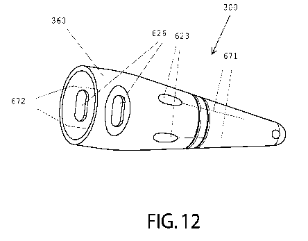
10 In one embodiment, as shown in FIGS. 11 & 12, the cone 300 can have
stabilization cavities 626 for receiving
the fingers of the user. The stabilization cavities 626 can allow for the cone
300 to be gripped, manipulated, stabilized,
or controlled while closing a wound. The stabilization cavities 626 can allow
for the cone 300 to be clamped or pinched
by the fingers of the surgeon or other suitable devices. The stabilization
cavities 626 can be positioned at any location
on the cone 300, for example, without limitation, the collar 360, body 310, or
the like. The stabilization cavities 626 can
15 penetrate through the entire thickness of the collar 360, or, as shown
in MG. 9, the stabilization cavities 626 can be a
cavity or depression that partially penetrates the thickness of the collar
360. For example, without limitation, the
stabilization cavities 626 can be cavities in the exterior surface of the
collar 360. In one embodiment, the stabilization
cavities 626 can be aligned with the exterior opening of a needle guidance
bore 621. For example, without limitation,
where the needle guidance bore 621 is positioned at a radial degree about the
exterior of the cone 300 of 0 , the
20 stabilization cavity 626 is positioned about the exterior of the cone
300 at a radial degree of 0 .
In one embodiment, the cone 300 has at least one circumferential indicator 629
to indicate the circumference of
the tissue lumen. The circumferential indicator 629 can be a mark, symbol, or
line having a distinguishing color, a
raised portion, or a recessed portion when compared to the surface of the cone
300. In one embodiment, the
circumferential indicator 629 is positioned on the surface of the body 310,
collar 360, or the like. The circumferential
indicator 629 can extend circumferentially about the exterior surface of the
cone 300. The circumference of the
circumferential indicator 629 can be any length, for example, without
limitation, the circumference of the
circumferential indicator 629 can be 2 mm - 40 mm. The circumferential
indicator 629 can be positioned in a plane
perpendicular to the longitudinal axis of the cone 300. The circumferential
indicator 629 can be positioned at a location
CA 03114574 2021-03-26
WO 2019/067578 PCT/US2018/052903
21
on the cone 300 that corresponds to the desired circumference of the tissue
lumen. For example, without limitation,
where the desired circumference of the tissue lumen is 25 mm, the
circumferential indicator 629 is positioned on the
cone 300 where the circumference of the cross-section of the cone 300 is 25
mm. By way of another example, without
limitation, where the desired circumference of the tissue lumen is 25 mm, the
circumferential indicator 629 is positioned
on the cone 300 where the distance between the circumferential indicator 629
and the distal end of the cone 300 is 30
mm.
The number of needle guidance bores 621 will depend on the size of the cone
300. In the preferred
embodiment, the cone 300 has four needle guidance bores 621a, 621b, 621c, and
621d. In one preferred embodiment,
needle guidance bores 621a and 621c are substantially parallel to each other
and needle guidance bores 621b and 621d
are substantially parallel to each other. In one embodiment, the needle
guidance bores 621 are positioned at an angle f3
in relation to the vertical longitudinal plane. The guide passageway 231 can
extend at an angle , from the horizontal
longitudinal plane P of the dilator 200. The angle can affect the depth of
the suture into the fascia. In one preferred
embodiment, needle guidance bores 621 are positioned at substantially equal
angles in relation to the axial plane 625.
The needle guidance bore 621 is located between the proximal hole 622 and the
distal hole 623. The proximal hole 622
can be located on the surface of the proximal cavity 340, exterior surface of
the body 310, or the like, and the distal hole
623 is located on the exterior surface 303 of the body 310.
As shown in FIGS. 9 ¨ 10, the angle f3 of the needle guidance bore 621 can
affect the distance D from the
exterior surface of the cone 300 the suture penetrates into the fascia. For
example, without limitation, a larger angle f3
will cause the distance D of the suture in the fascia to be greater and a
lesser angle f3 will cause the distance D of the
suture in the fascia to be less. While all suitable angles of the needle
guidance bores 621 are contemplated, the angle f3 is
preferably between 0 degrees and 90 degrees from axial line 625.
In one embodiment, the needle guidance bore 621 can extend longitudinally or
parallel to the longitudinal axis
of the cone. In one embodiment, the needle guidance bore 621 can have a right
handedness or left handedness. A right
handed needle guidance bore 621 allows for the user to insert the suture
passing device 650 through the needle guidance
bore 621 using the right hand. Where the needle guidance bore 621 has a right
handedness, the radial degrees about the
exterior of the cone 300 between the first opening 622 and the second opening
623 of the needle guidance bore 621 are
positive or rotate clockwise about the exterior of the cone 300, for example,
without limitation, the radial degrees can be
, 60 , 90 , or the like. A left handed needle guidance bore 621 allows for the
user to insert the suture passing device
CA 03114574 2021-03-26
WO 2019/067578 PCT/US2018/052903
22
650 through the needle guidance bore 621 using the left hand. Where the needle
guidance bore 621 has a left
handedness, the radial degrees about the exterior of the cone 300 between the
first opening 622 and the second opening
623 of the needle guidance bore 621 are negative or rotate counter clockwise
about the exterior of the cone, for example,
without limitation, the radial degrees can be -30 , -60 , -900, or the like.
In one embodiment, the cone 300 can have at
least one right handed needle guidance bore 621 and at least one left handed
needle guidance bore 621.
In one embodiment, the second opening 623 is positioned in relation to the
circumferential indicator 629 to
allow the suture passing device 650 to pass through the cross-sectional plane,
in which the circumferential indicator 629
is positioned, outside of the circumference of the circumferential indicator
629. For example, without limitation, the
second opening 623 can be positioned proximate to the circumferential
indicator 629.
In one embodiment, the angle f3 of the needle guidance bore 621 and distance
between the second opening 623
and the circumferential indicator 629 are coordinated to allow for the suture
passing device 650 to pass through the
cross-sectional plane, in which the circumferential indicator 629 is
positioned, at a desired distance D from the exterior
surface of the cone 300. This ensures the suture pulls the tissue lumen closed
without tearing through fascia. The angle
f3 of the needle guidance bore 621 can be within the ranges of 0 and 60 and
the distance between the second opening
.. 623 and the circumferential indicator 629 can be within the ranges of 5mm
and 75mm. For example, without limitation,
where the circumference of the circumferential indicator 629 is 2 mm to 40 mm
and the desired distance of the suture
insertion point is 5mm to 15mm outside the circumference of the
circumferential indicator 629, the distance between the
second opening 623 and the circumferential indicator 629 is within the range
of 5 mm - 75 mm and the angle f3 of the
needle guidance bore 621 is within the range of -0 - -60 . By way of another
example, without limitation, where the
.. circumference of the circumferential indicator 629 is 2mm to 40mm and the
desired distance of the suture insertion point
is 5 mm to 15mm outside the circumference of the circumferential indicator
629, the distance between the second
opening 623 and the circumferential indicator 629 is within the range of 5mm -
75mm and the angle f3 of the needle
guidance bore 621 is within the range of 0 - 600
.
In one embodiment, as shown in FIG. 11, the cone 300 can have an interior
insertion indicator 671 for
indicating the radial position of the distal hole 623. In one embodiment, the
interior insertion indicator 671 indicates the
radial position on the cone 300 where the suture passing device 650 will exit
through the distal hole 623 and thus the
radial position on the interior surface of the tissue lumen of where the
suture will be inserted into the fascia. The interior
insertion indicator 671 can be a mark, symbol, or line having a distinguishing
color, a raised portion, or a recessed
CA 03114574 2021-03-26
WO 2019/067578
PCT/US2018/052903
23
portion when compared to the surface of the cone. The interior insertion
indicator can 671 be positioned at any location
on the cone 300 that allows for the interior insertion indicator 671 to be
viewed from inside of the abdomen. The
surgeon can view the indication in the inside of the abdomen by way of a
surgical camera, or the like. While the interior
insertion indicator 671 can be positioned at any location on the cone 300, the
interior insertion indicator can be
positioned on the surface of the body 310, collar 360, or the like. The
interior insertion indicator 671 can extend
longitudinally along the exterior surface of the cone 300. The interior
insertion indicator 671 can extend from the distal
hole 623 toward the distal end 302 of the cone 300. The interior insertion
indicator 671 can extend along the exterior
surface of the body 310. The interior insertion indicator 671 can extend from
the circumferential indicator 629 to the
distal end 302 of the cone 300.
In one embodiment, as shown in MG. 12, the cone 300 can have an exterior
insertion indicator 672 for
indicating the radial position of the proximal hole 622. In one embodiment,
the exterior insertion indicator 672 indicates
the radial position on the cone 300 where the suture passing device 650 will
enter through the proximal hole 622 and
thus allow the surgeon to determine the radial position on the interior
surface of the tissue lumen of where the suture will
be inserted into the fascia. The exterior insertion indicator 672 can be a
mark, symbol, or line having a distinguishing
color, a raised portion, or a recessed portion when compared to the surface of
the cone 300. While the exterior insertion
indicator 672 can be positioned at any location on the cone 300, the exterior
insertion indicator 672 can be positioned on
the surface of body 310, collar 630, or the like. The exterior insertion
indicator 672 can be positioned at any location on
the cone 300 that allows for the exterior insertion indicator 672 to be viewed
from the exterior of the abdomen. The
exterior insertion indicator 672 can extend longitudinally along the exterior
surface of the cone 300. The exterior
insertion indicator 672 can extend from the proximal hole 622 toward the
distal end 302 and/or proximate end 301 of the
cone 300.
In one embodiment, the cone 300 has a closure system 600 for closing a wound.
The number of needle
guidance bores 621 will depend on the size of the cone 300. In the preferred
embodiment, the cone 300 has four needle
guidance bores 621a, 621b, 621c, and 621d. In one preferred embodiment, needle
guidance bores 621a and 621c are
substantially parallel to each other and needle guidance bores 621b and 621d
are substantially parallel to each other. In
one preferred embodiment, needle guidance bores 621 are positioned at
substantially equal angles in relation to axial line
625. The needle guidance bore 621 has a proximal hole 622 and a distal hole
623 where the needle guidance bore 621
is positioned so that the proximal hole 622 is located on the surface of the
proximal cavity 340 and the distal hole 623 is
CA 03114574 2021-03-26
WO 2019/067578 PCT/US2018/052903
24
located on the exterior surface 303 of the cone 300. While all suitable angles
of the needle guidance bores 621 are
contemplated, the angle f3 is preferably between 0 degrees and 60 degrees from
axial line 625.
In one embodiment, end 641 of the suture passes through the proximal hole 622a
of needle guidance bore 621a,
passes through the needle guidance bore 621a, exits the distal hole 623a of
needle guidance bore 621a, passes through
the desired bodily tissue 660 to be closed, and into the body cavity. The end
641 is retrieved and pulled through the
desired bodily tissue 660 to be closed, passes through the distal hole 623b of
needle guidance bore 621b, passes through
the needle guidance bore 621b, and exits through the proximal hole 622b of
needle guidance bore 621b. The suture can
pass through the needle guidance bore 621 and holes 622, 623 with the aid of a
suture passing device 650, or the like.
The cone 300 is then removed from the tissue lumen utilizing the guide 610 and
closure is standardly performed.
In the preferred embodiment, as shown in FIGS. 6c-6d, while retaining one end
642 of an closing suture 640
external to the closing device 600 and the body cavity, the other end 641 of
the closing suture 640 is passed with a suture
passing device 650 through the proximal hole 622a of needle guidance bore
621a, through the needle guidance bore
621a, through the distal hole 623a of needle guidance bore 621a, through the
desired bodily tissue 660 to be closed, and
into the body cavity. The end 641 of the closing suture 640 is released and
temporarily left in the body cavity. The
suture passing device 650 without end 641 or end 642 is passed through the
proximal hole 622b of needle guidance bore
621b, through the needle guidance bore 621b, through the distal hole 623b of
needle guidance bore 621b, through the
opposite side of the desired bodily tissue 660 to be closed, and into the body
cavity. The end 641 is grasped by the
suture passing device 650 and pulled through the bodily tissue 660, through
the distal hole 623b of needle guidance bore
621b, through the needle guidance bore 621b, and through the proximal hole
622b. Both ends 641 and 642 are then
secured and the cone 300 is removed from the tissue lumen utilizing the guide
610 and slid over the two ends 641 and
642 of the closing suture 640. The two ends 641 and 642 of the closing suture
640 are then tied to close the tissue lumen
in traditional fashion. This can be repeated with additional closure sutures
640 through the plurality of needle guidance
bores 621 or by using the retrieval guidance member 610 to redirect the
orientation of needle guidance bores 621 and
therefore the placement of the additional closure sutures 640.
The dilator 200, cone 300, closure system 600, and guide 610 may be
constructed from any suitable material or
combinations of materials including acceptable sterilizable medical grade
material or combinations of materials. For
example, without limitation, the dilator 200, cone 300, closure system 600,
and guide 610 may be formed of stainless
steel, surgical steel, titanium alloy, one or more moldable and/or
thermoformable plastics, polymers, composites which
CA 03114574 2021-03-26
WO 2019/067578 PCT/US2018/052903
is or are sufficiently rigidity for passage through or creation of a tissue
lumen. The dilator 200, cone 300, closure system
600, and guide 610 can be manufactured by an injection molding process, a blow
molding process with secondary slit, or
other processes.
As used herein, the singular forms "a", "an" and "the" are intended to include
the plural forms as well, unless
5 expressly stated otherwise. It will be further understood that the terms
"includes," "comprises," "including" and/or
"comprising," when used in this specification, specify the presence of stated
features, integers, steps, operations,
elements, and/or components, but do not preclude the presence or addition of
one or more other features, integers, steps,
operations, elements, components, and/or groups thereof. It will be understood
that when an element is referred to as
being "connected" or "coupled" to another element, it can be directly
connected or coupled to the other element or
10 intervening elements may be present. Furthermore, "connected" or
"coupled" as used herein may include wirelessly
connected or coupled. As used herein, the term "and/or" includes any and all
combinations of one or more of the
associated listed items. In addition, the term "or" is used in its inclusive
sense (and not in its exclusive sense) so that
when used, for example, to connect a list of elements, the term "or" means
one, some, or all of the elements in the list.
Conditional words "can," "could," "might," "may," "e.g.," and the like, unless
stated otherwise, are intended to
15 convey that certain embodiments include, while other embodiments do not
include, certain features, elements and/or
steps. Such conditional language does not convey features, elements and/or
steps are required for one or more
embodiments, whether such features, elements and/or steps are included or are
to be performed in any particular
embodiment.
Disjunctive language such as the phrase "at least one of A, B, or C," unless
specifically stated otherwise, is
20 understood that an item, term, or the like, may be either A, B, or C, or
any combination thereof (for example, A, B,
and/or C). Such disjunctive language should not be interpreted that certain
embodiments require at least one of X, at
least one of Y, and at least one of Z to each be present.
The foregoing has described the principles, embodiments, and modes of
operation of the present invention.
However, the invention should not be construed as being limited to the
particular embodiments described above, as they
25 should be regarded as being illustrative and not as restrictive. It
should be appreciated that variations may be made in
those embodiments by those skilled in the art without departing from the scope
of the present invention.
Modifications and variations of the present invention are possible in light of
the above teachings. It is therefore
to be understood that the invention may be practiced otherwise than as
specifically described herein.