Note: Descriptions are shown in the official language in which they were submitted.
Atty Dkt No NIB001 P524
MULTI-PORT TRANSITION TEE DRAIN VALVE
BACKGROUND OF THE INVENTION
[0001] The present invention relates to a drain valve. Valves
incorporating drains can be used to
drain all or part of the plumbing components near the drain valve. Drain
valves can be used in a
variety of plumbing applications, including, but not limited to, potable
plumbing or hydronic
heating systems. Drain valves that are incorporated into a system typically
permit draining either
above or below the valve by a drain segment that was positioned, as a separate
component,
above or below the drain valve. A number of components are typically necessary
to couple a
drain, a valve, and other piping unions when branch assemblies lead to and
from the valve. This
typically includes at least one segment of piping in between the drain, valve,
piping union, and/or
additional other components. This creates additional leak paths, takes
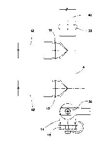
additional time to
assemble, and takes space given the number of components especially when
transitioning from
one type of size of tubing/piping to another. In addition, multiple components
are typically
necessary when there are multiple inlet and/or outlet fittings near the drain
port.
[0002] An improved assembly that eliminates a number of components and
potential leak paths
and provides multiple inlet and/or outlet ports while saving assembly time,
labor, and space, is
described herein.
SUMMARY OF THE INVENTION
[0003] One aspect of the present invention is a multi-port tee drain
valve. The multi-port tee
drain valve includes a fitting body having a first end portion, a second end
portion, a fluid
passageway extending between the first end portion and the second end portion,
and at least
two ports located between the first end portion and the second end portion.
The ports are
positioned generally perpendicular to the fluid passageway of the fitting
body. The multi-port tee
drain valve also includes a drain port located in the first end portion, a
first fitting located at the
second end portion, and a valve member located in the first end portion that
is positioned
between the drain port and the ports. The ports have fitting ends.
[0004] Another aspect of the present invention is a drain valve assembly.
The drain valve
assembly includes a drain valve body having a first end portion with a drain
port, a second end
1
Date Recue/Date Received 2022-08-11
portion with a first fitting end, and a fluid passageway extending between the
first end portion
and the second end portion. The drain valve body also includes at least two
ports located
between the first end portion and the second end portion, with the ports being
positioned
generally perpendicular to the fluid passageway. The drain valve assembly
includes a valve
member that is located in the first end portion between the drain port and the
ports. The ports
have fitting ends.
[0005] Yet another aspect of the present invention is a multi-port
transition tee drain valve. The
multi-port transition tee drain valve includes a drain valve body having a
first end portion with
a drain port, a second end portion with a first fitting end, and a fluid
passageway extending
between the first end portion and the second end portion. The drain valve body
also has at least
two ports located between the first end portion and the second end portion.
The ports are
positioned generally perpendicular to the fluid passageway. The multi-port
transition tee drain
valve also includes a valve member located in the first end portion between
the drain port and
the ports. The ports have fitting ends that are different than the first
fitting end of the second
end portion of the drain valve body.
[0006] These and other features, advantages, and objects of the present
invention will be further
understood and appreciated by those skilled in the art by reference to the
following specification,
claims, and appended drawings.
[0006a] According to another aspect, there is provided a multi-port tee
drain valve, comprising a
fitting body having a first end portion, a second end portion, a fluid
passageway extending
between said first end portion and said second end portion, and at least two
ports located
between said first end portion and said second end portion, said at least two
ports positioned
generally perpendicular to said fluid passageway, a drain port located in said
first end portion,
said drain port having a centerline that is coaxial with the centerline of
said fluid passageway, a
first fitting located in said second end portion, said first fitting having a
centerline that is coaxial
with the centerline of said fluid passageway, a valve member located in said
first end portion
positioned in the fluid passageway between said drain port and said at least
two ports and said
at least two ports having fitting ends.
2
Date Recue/Date Received 2022-08-11
[0006b] According to another aspect, there is provided a drain valve
assembly, comprising
a drain valve body having a first end portion with a drain port, a second end
portion with
a first fitting end, a fluid passageway extending between said first end
portion and said
second end portion, said fluid passageway having a centerline that is coaxial
with the
centerline of said drain port and said first fitting end, at least two ports
located between
said first end portion and said second end portion, said at least two ports
being positioned
generally perpendicular to said fluid passageway, a valve member located in
said first end
portion of said fluid passageway positioned between said drain port and said
at least two
ports and said at least two ports having fitting ends.
[0006c] According to yet another aspect, there is provided a multi-port
transition tee drain
valve, comprising a drain valve body having a first end portion with a drain
port, a second
end portion with a first fitting end, a fluid passageway extending between
said first end
portion and said second end portion, said fluid passageway having a centerline
that is
coaxial with the centerline of said drain port and said first fitting end, at
least two ports
located between said first end portion and said second end portion, said at
least two ports
being positioned generally perpendicular to said fluid passageway, a valve
member
located in said first end portion of said fluid passageway positioned between
said drain
port and said at least two ports and said at least two ports having fitting
ends that are
different than said first fitting end.
BRIEF DESCRIPTION OF THE DRAWINGS
[0007] In the drawings:
[0008] FIG. 1 is a front view of one embodiment of a multi-port transition
tee drain valve;
[0009] FIG. 2 is a front view of the multi-port transition tee drain valve
shown in FIG. 1
coupled to tubing;
[0010] FIG. 3 is a front view of the multi-port transition tee drain valve
shown in FIG. 1,
oriented with the drain port in a generally vertical orientation, coupled to
tubing;
[0011] FIG. 4 is a front view of an embodiment of a multi-port transition
tee that does not
have a drain port or valve member;
2a
Date Recue/Date Received 2022-08-11
[0012] FIG. 5 is a front view another embodiment of a multi-port
transition tee;
[0013] FIG. 6 is a front view of an embodiment of a single port transition
tee drain valve;
2b
Date Regue/Date Received 2022-08-11
[0014] FIG. 7 is a front view of a multi-port transition tee;
[0015] FIG. 8 is a rotated cross-sectional view of the drain valve body of
the multi-port transition
tee drain valve shown in FIG. 1;
[0016] FIG. 9 is a front perspective view of a plug;
[0017] FIG. 10 is a partial front perspective view of the plug of FIG. 9
installed in the second end
portion of the multi-port transition tee drain valve of FIG. 1; and
[0018] FIG. 11 is a cross-sectional view of the plug shown in FIG. 9.
DETAILED DESCRIPTION
[0019] For purposes of description herein, the terms "upper," "lower,"
"right," "left," "rear,"
"front," "vertical," "horizontal," and derivatives thereof shall relate to the
invention as oriented
in FIGS. 1-7. However, it is to be understood that the invention may assume
various alternative
orientations and step sequences, except where expressly specified to the
contrary. Indeed, other
exemplary orientations are shown in the Figures. It is also to be understood
that the specific
devices and processes illustrated in the attached drawings, and described in
the following
specification, are simply exemplary embodiments of the inventive concepts
defined in the
appended claims. Hence, specific dimensions and other physical characteristics
relating to the
embodiments disclosed herein are not to be considered as limiting, unless the
claims expressly
state otherwise.
[0020] Detailed embodiments of the present invention are disclosed herein,
however, it is to be
understood that the disclosed embodiments are merely exemplary of the
invention, which may
be embodied in various forms. Therefore, specific functional or structural
details disclosed herein
are not to be interpreted as limiting, but merely as a basis for the claims
and as a representative
basis for teaching one skilled in the art to variously employ the present
invention in virtually any
appropriately detailed embodiment.
[0021] By way of overview, the present invention is generally directed to
a multi-port transition
tee drain valve 2, as shown in FIG. 1. The multi-port transition tee drain
valve 2 includes a body
4 having a first end portion 6 and a second end portion 8. A fluid passageway
5 extends from the
first end portion 6 to the second end portion 8. The body 4 also includes a
number of ports 10.
3
Date Recue/Date Received 2021-04-13
The ports 10 are positioned generally perpendicular to the fluid passageway 5
thus forming a
multi-port tee when multiple ports 10 are used on the body 4.
[0022] The first end portion 6 includes a drain port 14, as illustrated in
FIG. 1. Drain port 14 can
be closed with a cap 16, as illustrated in FIG. 1. The cap 16 can be pressed
onto the drain port 14
or other mechanisms can be used to couple the cap 16 to drain port 14,
including, but not limited
to, the use of threaded surfaces in the drain port 14 and cap 16.
[0023] The second end portion 8 includes a first fitting end 22. In the
illustrated embodiment of
FIGS. 1-3 and 8, the first fitting end 22 is a press fitting. The first
fitting end 22 can be any type of
fitting, including, but not limited to, PEX, female pipe thread, male pipe
thread, traditional solder,
push-to-connect, press-to-connect, fusion, etc.
[0024] The ports 10 include fitting ends 12. The fitting ends 12 can be
any type of fitting end. In
the illustrated embodiment, the fitting end 12 is a PEX fitting end. However,
any type of fitting
end can be used for the fitting end 12 on ports 10. This includes, but is not
limited to, female pipe
thread, male pipe thread, traditional solder, push-to-connect, press-to-
connect, fusion, etc. In
the illustrated embodiment of FIGS. 1-3 and 8, the ports 10 include a PEX
fitting, while the second
end portion 8 includes a press fitting. This, thus, allows the transition of
different types of fittings
and/or different types or sizes of tubing/piping on the multi-port transition
tee drain valve 2. As
illustrated in FIG. 2, the tubing 42 can be connected to the fitting 12 on
ports 10, while a different
type of piping 40 can be connected to the first fitting end 22 of the second
end portion 8 of the
body 4. In the embodiment shown in FIGS. 2 and 3, the tubing 42 is PEX tubing
and the piping 40
is copper piping. Other types of tubing or piping can be used depending upon
the fittings that are
present on the body 4.
[0025] A valve member 30 is located at the first end portion 6 of the body
4 in the embodiment
illustrated in FIGS. 1-3 and 6. The valve member 30 includes a handle 32 that
is secured to a stem
(not shown) by fastener 34. The valve member 30 opens and closes the fluid
passageway 5 in the
first end portion 6 near the drain port 14. Thus, the valve member 30 can be
opened to permit
the draining of the multi-port transition tee drain valve 2 and some of the
associated tubing/
piping (40, 42) and potentially other close components within the plumbing
system by the
opening of valve member 30 and the removal of cap 16. The body 4 can include
an integral valve
4
Date Recue/Date Received 2021-04-13
housing 44 that includes a stem opening 46 formed within the body 4, as
illustrated in FIG. 8. This
permits the insertion of a ball (not shown) into the fluid passageway 5 below
the stem opening
46. The ball can be seated in the ball seating area 48 through the use of
seals (not shown) that
engage surfaces on the body 4. A stem is inserted through stem opening 46 and
coupled to the
ball and the handle 32 is coupled to the stem to create the valve member 30.
FIGS. 1-3 and 8
illustrate an embodiment wherein the valve housing 44 for the valve member 30
is formed
integrally with the body 4 of the multi-port transition tee drain valve 2.
Thus, the body 4 can be
a single unitary piece. However, the valve housing 44 and drain port 14 could
be part of a separate
piece(s) that is coupled to the remainder of the body 4. The body 4 can be
made from any
material, including, but not limited to, brass.
[0026] While the embodiment illustrated in FIGS. 1-3 and 8 illustrate two
ports 10, three or more
ports 10 can also be utilized with the multi-port transition tee drain valve
2. In addition, while the
embodiment illustrated in FIGS. 1-3 shows the handle 32 on the side of the
body 4 while the ports
are on the upper surface of the body 4, the valve member 30 can be positioned
such that the
handle is on the same side (top) of the body 4 as the ports 10, on the
opposite side (bottom) of
the body 4 as the ports 10, or on the other side of the body 4. The
alternative positions of the
valve member 30 on the body 4 with respect to the ports 10 gives different
options for
installation. For example, the positioning of the valve member 30 in one of
the alternative
positions on the body 4 may make it easier to access the handle 32 depending
upon surrounding
piping, plumbing components, appliances, or other objects that create space
and/or accessibility
issues.
[0027] An embodiment of a multi-port transition tee 100 is illustrated in
FIG. 4. This multi-port
transition tee 100 is similar to the multi-port transition tee drain valve 2
shown in FIGS. 1-3
without a drain port 14 or a valve member 30. The body 104 includes a first
fitting end 122 on
the second end portion 108 and a second fitting end 150 on the first end
portion 106, with two
ports 110 that are perpendicular to the fluid passageway 105 extending between
the first fitting
end 122 and the second fitting end 150. In the embodiment illustrated in FIG.
4, the first fitting
end 122 and the second fitting end 150 are the same type of fitting. In the
illustrated
embodiment, the first fitting end 122 and the second fitting end 150 are both
press fittings.
5
Date Recue/Date Received 2021-04-13
However, other types of fittings can be used. The ports 110 having fitting
ends 112 that are PEX
fitting ends. However, other types of fittings can be used.
[0028] FIG. 5 illustrates an alternative embodiment of a multi-port
transition tee 200 wherein
the body 204, having fluid passageway 205, does not include a second fitting
end at the first end
portion 206. The illustrated embodiment has a first fitting end 222 at the
second end portion 208
and fitting ends 212 on ports 210. Again, the fittings (222, 212) can be any
type of fitting, including
those that permit the transition from different types and/or sizes of tubing
or piping.
[0029] FIG. 6 illustrates a single port transition tee drain valve 300.
The single port transition tee
drain valve 300 with fluid passageway 305 is similar to the multi-port
transition tee drain valve 2,
illustrated in FIGS. 1-3, with the exception of there being a single port 310.
As illustrated in FIG.
6, the single port 310 includes a fitting end 312 that is different from the
first fitting end 322 on
the second end portion 308 on the body 304, thus permitting a transition for
different types or
sizes of tubing/piping. The single port transition tee drain valve 300
includes a drain port 314 with
a removable cap 316 adjacent to a valve member 330.
[0030] FIG. 7 illustrates a multi-port transition tee 400 with body 404
with three ports 410. The
three ports 410 are positioned generally perpendicular to the fluid passageway
405 between the
first end portion 406 and the second end portion 408. The fittings include a
first fitting end 422
on the second end portion 408, a second fitting 450 on the first end portion
406, and fittings 412
on ports 410. Again, any type of fitting can be used on fittings 412, 450, and
422, including those
that permit the transition between different sizes and/or types of tubing or
piping.
[0031] While the illustrated embodiments show ports (10, 110, 210, 310,
410) all having the
same type of fittings, different ports on the same body (4, 104, 204, 304,
404) can have different
fittings. In addition, one or more of the ports (10, 110, 210, 310, 410) may
have the same type of
fittings as the first fitting end (22, 122, 222, 322, 422).
[0032] A plug 700 can be coupled to the first fitting end 22 of the second
end portion 8, as shown
in FIG. 10. The plug 700 can also be coupled to the second fitting end 150.
The plug 700 includes
a generally cylindrical sidewall 708 and a generally cylindrical rim 702 that
has a wider diameter
than the generally cylindrical sidewall 708. A tapered surface 704 is
positioned at the transition
between the generally cylindrical sidewall 708 to the general cylindrical rim
702. The plug 700
6
Date Recue/Date Received 2021-04-13
includes an end surface 706. The angle 712 between the generally cylindrical
sidewall 708 and
the generally cylindrical rim 702 is in the range of 105 to 165 , and more
preferably
approximately 135 . The plug 700 can be made from any material, but is
preferably made from
brass. The plug 700 can be coupled to the fitting end (22, 150) by a pressing
tool, allowing the
user to cap off one of the ends of the body 404. The plug 700 can
alternatively have a threaded
surface that can couple to a threaded surface on the fitting end (22, 150).
[0033] In the foregoing description, it will be readily appreciated by
those skilled in the art that
modifications may be made to the invention without departing from the concepts
disclosed
herein. Such modifications are to be considered as included in the following
claims, unless these
claims by their language expressly state otherwise.
[0034] It will be understood by one having ordinary skill in the art that
construction of the
present disclosure and other components is not limited to any specific
material. Other exemplary
embodiments of the disclosure disclosed herein may be formed from a wide
variety of materials,
unless described otherwise herein.
[0035] For purposes of this disclosure, the term "coupled" or "operably
coupled" (in all of its
forms, couple, coupling, coupled, etc.) generally means the joining of two
components (electrical
or mechanical) directly or indirectly to one another. Such joining may be
stationary in nature or
movable in nature. Such joining may be achieved with the two components
(electrical or
mechanical) and any additional intermediate members being integrally formed as
a single unitary
body with one another or with the two components. Such joining may be
permanent in nature
or may be removable or releasable in nature unless otherwise stated. In
addition, while certain
embodiments have shown threaded connections, the threaded connections could
include tape
or other sealing material in the threaded connection. In addition, the
threaded connection could
be replaced by other suitable connections or couplings, such as compression
couplings or other
couplings.
[0036] For purposes of this disclosure, the term "connected" or "operably
connected" (in all of
its forms, connect, connecting, connected, etc.) generally means that one
component functions
with respect to another component, even if there are other components located
between the
7
Date Recue/Date Received 2021-04-13
first and second component, and the term "operable" defines a functional
relationship between
components.
[0037] It is also important to note that the construction and arrangement
of the elements of the
present disclosure as shown in the exemplary embodiments is illustrative only.
Although only a
few embodiments of the present innovations have been described in detail in
this disclosure,
those skilled in the art who review this disclosure will readily appreciate
that, unless otherwise
described, many modifications are possible (e.g., variations in sizes,
dimensions, structures,
shapes and proportions of the various elements, values of parameters, mounting
arrangements,
use of materials, colors, orientations, etc.) without materially departing
from the novel teachings
and advantages of the subject matter recited. For example, elements shown as
integrally formed
may be constructed of multiple parts or elements shown as multiple parts may
be integrally
formed, the operation of the interfaces may be reversed or otherwise varied,
the length or width
of the structures and/or members or connector or other elements of the system
may be varied,
the nature or number of adjustment positions provided between the elements may
be varied. It
should be noted that the elements and/or assemblies of the system may be
constructed from
any of a wide variety of materials that provide sufficient strength or
durability, in any of a wide
variety of colors, textures, and combinations. Accordingly, all such
modifications are intended to
be included within the scope of the present innovations. Other substitutions,
modifications,
changes, and omissions may be made in the design, operating positions, and
arrangement of the
desired and other exemplary embodiments without departing from the spirit of
the present
innovations.
[0038] It will be understood that any described processes or steps within
described processes
may be combined with other disclosed processes or steps to form structures
within the scope of
the present disclosure. The exemplary structures and processes disclosed
herein are for
illustrative purposes and are not to be construed as limiting.
[0039] It is also to be understood that variations and modifications can
be made on the afore-
mentioned structures and methods without departing from the concepts of the
present
invention, and further it is to be understood that such concepts are intended
to be covered by
the following claims unless these claims by their language expressly state
otherwise.
8
Date Recue/Date Received 2021-04-13