Note: Descriptions are shown in the official language in which they were submitted.
COLLAPSIBLE SHOE HEEL
FIELD OF THE EMBODIMENTS
The field of the present invention and its embodiments relate to a collapsible
shoe heel
configured to be received and integrated into a sole of a shoe, such as a
moccasin, a sneaker, a
dress shoe, a high heel shoe, and/or a sandal, among others.
BACKGROUND OF THE EMBODIMENTS
Laced shoes provide greater foot support and protection than do unlaced
loafers and
sandals. Their insertion and removal from the foot requires greater effort.
Shortcutting shoe
removal without untying the laces is damaging to the back of the shoe, over
time breaking down
its structural integrity.
The present invention provides internal spring support within the back of
laced shoes, the
spring biasing the shoe back in a raised configuration. When putting on or
taking off the shoe,
pushing down on the back of the shoe overcomes the spring force and lowers the
shoe back,
easing foot insertion or removal. Once the shoe is on the foot or removed, the
downward force
against the shoe back ceases, the spring recovers, raising the shoe back.
Review of related technology:
United States Patent No.: 2,198,228 pertains to a rubber heel to provide
improved bonds
between the top plate and the body of the heel; to provide improved
Ventilating systems for the
heel; to provide improved attachments of the heel to the shoe; and to provide
a novel reinforced
heel.
1
Date Recue/Date Received 2021-04-21
United States Patent No.: 3,174,234 pertains to a shoe heel having a movable
door or wall
which can be opened to expose a compaiiment in which a collapsed overshoe is
stored. In one
form of the invention, the overshoe has a sole engaged at one end in the
compartment to hold the
overshoe on the shoe when in operative position.
United States Patent No.: 3,431,658 pertains to foot coverings such as boots,
shoes and
the like. More particularly, it is concerned with providing boots and shoes
with means to assure a
tight and snug fit, said means comprising broadly an expandable bellows
disposed in the counter
area.
United States Patent No.: 6,298,583 pertains to a camp shoe that is similar in
most
aspects to a typical shoe. However, to make it easy to pack and tote in a
knapsack, for example,
this shoe has construction features that permit it to be folded flat to
conform with sole of the shoe
and, therefore, be easily tucked in and toted in luggage where spare space is
typically at a
premium. The construction features include a rigid heel counter; a heel
support flexibly attached
to said heel counter; a pair of upper ankle supports flexibly attached to said
heel support; and a
pair of lower ankle supports flexibly attached to said upper ankle supports
and said heel counter.
United States Patent No.: 7,168,190 pertains to an article of footwear
including an upper
formed of a flexible upper material and a sole formed of a flexible sole
material, wherein the sole
is rolled, folded, or collapsed onto itself to reduce the volume of the
article of footwear. The
article of footwear in a collapsed state can then be packaged in a container.
This container can be
dispensed by a vending machine in a convenient urban area.
United States Patent No.: 7,578,075 pertains to a shoe having a removable
heel,
removable platform, and in some embodiments one or more removable straps. The
removable
shoe provides for flexibility in design with the same sole by allowing for
replacement of one type
2
Date Recue/Date Received 2021-04-21
of heel with another and in some shoes replacement of the strap or straps by
alternate styles or
colors of straps. The replaceability or modularity of the heel and straps
allows for compact
storage as well, which is desirable during travel. The removeability of the
platform enables the
shoe to adjust to different heights. Additionally, some embodiments have one
or more hinges
formed in the sole to allow the shoe to collapse to an even smaller size for
storage or travel.
United States Patent No.: 8,020,320 pertains to an article of footwear
including an upper
formed of a flexible upper material and a sole formed of a flexible sole
material, wherein the sole
is rolled, folded, or collapsed onto itself to reduce the volume of the
article of footwear. The
article of footwear in a collapsed state can then be packaged in a container.
This container can be
dispensed by a vending machine in a convenient urban area.
United States Patent Publication No.: 2002/0129519 pertains to a shoe that
includes a
sole and a collapsible upper attached to the sole. The upper includes a vamp
portion to be worn
around the toes and forepart of a foot of a wearer, a heel portion to be worn
adjacent the heel of
the wearer, side portions provided between the vamp portion and the heel
portion to be worn
adjacent the sides of the foot of the wearer, and insets, at least one inset
being provided between
each side portion and the heel portion of the upper. The insets are made of a
thin, flexible
material which can be easily folded to allow the vamp portion, side portions
and heel portion of
the upper to collapse onto the sole when not being worn.
United States Patent Publication No.: 2005/0050772 pertains to an improved
expandable
shoe and inner assembly are disclosed. The expandable shoe includes an outer
shell and an
adjustable inner assembly is disposed within the outer shell. The inner
assembly has a first board
portion and a second board portion in overlapping engagement with each other
and a control to
adjust the position of the first board portion relative to the second board
portion. A lighted
3
Date Recue/Date Received 2021-04-21
visualization window provides a visualization window to the inner assembly.
The inner assembly
may include size markings through the visualization window so that a size of
the adjusted shoe
may be determined as shoe size is adjusted.
Chinese Patent Document No.: CN201860884U pertains to a pair of heel-
adjustable
shoes which comprise shoe surfaces and heals of the heel-adjustable shoes,
wherein the lower
end in each heel is connected with a foldable heel by a folding, the upper
surface of the foldable
heel at the upper end of the folding is provided with a plurality of mother
buttons, the upper
surface of the foldable heel at the lower end of the folding is provided with
a plurality of son
buttons, and the mother buttons and the son buttons are arranged with one
another oppositely.
The heel-adjustable shoes have the characteristics of being compact and
ingenious in structure,
practical in function and the like, thereby being capable of optionally
adjusting the heights of the
heels as required, and leading a user to be comfortable to wear the high-
heeled shoes.
Chinese Patent Document No.: CN202514680U pertains to a pair of foldable high-
heeled
shoes, which comprises shoe bodies and is characterized in that the back part
of each shoe body
is provided with a connecting block; the front part of each connecting block
is hinged with a heel
through a revolving shaft; a fixing device is arranged between each heel and
the corresponding
connecting block; and magnets which are matched with each other are arranged
on the middle
part of each sole and the front part of the corresponding heel respectively.
The foldable high-
heeled shoes are simple in structure, are convenient for using, are foldable,
can be taken as a pair
of high-heeled shoes as well as a pair of flat-heeled shoes, and are suitable
for various occasions.
Chinese Patent Document No.: CN2862772Y pertains to a foldaway high and flat-
heeled
dual-purpose shoe. In detail, it is characterized in that: two foldaway heels
are divided into the
front and back end of heel. Back end and back-end joint is linked by locating
hinge on the edge
4
Date Recue/Date Received 2021-04-21
of back end. Moreover, demands for flat-heeled shoe on some occasions by
folding back-end of
heel based on above structure can be met, thus fulfilling the aims of utility
model.
Various systems and methodologies are known in the art. However, their
structure and
means of operation are substantially different from the present disclosure.
The other inventions
fail to solve all the problems taught by the present disclosure. At least one
embodiment of this
invention is presented in the drawings below and will be described in more
detail herein.
SUMMARY OF THE EMBODIMENTS
The present invention and its embodiments relate to collapsible shoe heel
configured to
be received and integrated into a sole of a shoe, such as a moccasin, a
sneaker, a dress shoe, a
high heel shoe, and/or a sandal, among others.
A first embodiment of the present invention describes a shoe. The shoe
includes a first
member configured to be received at a first location in a sole of a shoe and a
second member
configured to be received at a second location in the sole of the shoe. The
first location differs
from the second location. It should be appreciated that each of the first
member and the second
member comprise a cloth material or a fabric material. The shoe also includes
a collapsible shoe
heel that is configured to be received and integrated into the sole of the
shoe.
The collapsible shoe heel includes a support member, a lifting member, a first
hinge, and
a second hinge. The support member has a first end disposed opposite a second
end. The second
end of the support member comprises a support structure. The support structure
is configured to
provide support to the second end of the support member.
The lifting member has a first end disposed opposite a second end. The first
end of the
lifting member has a rounded curve and comprises a protrusion section. The
protrusion section is
5
Date Recue/Date Received 2021-04-21
configured to provide support to a portion of the shoe being lifted by the
lifting member. The
first end of the lifting member is received by a tube portion. The tube
portion comprises a
silicone material. Moreover, the second end of the lifting member comprises a
support structure.
An angle is formed between the second end of the support member and the second
end of
the lifting member. It should be appreciated that the angle is a 30 degree
angle when the lifting
member is in an expanded position without an application of force. Moreover,
the first hinge
rotatably connects the second end of the support member and the second end of
the lifting
member. The second hinge rotatably connects the second end of the support
member and the
second end of the lifting member. In examples, each of the first hinge and the
second hinge
comprise a torsional spring.
The first hinge is received by a first cylindrical portion and is then
received in the sole of
the shoe at the first location on top of the first member. The second hinge is
received by a second
cylindrical portion and is then received in the sole of the shoe at the second
location on top of the
second member. In examples, each of the first cylindrical portion and the
second cylindrical
portion comprise a plastic material. Each of the first hinge and the second
hinge are configured
to define the angle.
A second embodiment of the present invention describes a shoe. The shoe
includes a first
member configured to be received at a first location in a sole of a shoe and a
second member
configured to be received at a second location in the sole of the shoe. The
first location differs
from the second location. Moreover, each of the first member and the second
member comprise a
cloth material or a fabric material.
The shoe also includes a collapsible shoe heel configured to be received and
integrated
into the sole of the shoe. The collapsible shoe heel includes a support
member, a lifting member,
6
Date Recue/Date Received 2021-04-21
an angle, a first hinge, and a second hinge. The support member has a first
end disposed opposite
a second end. The lifting member has a first end disposed opposite a second
end. The first end of
the lifting member has a rounded curve and comprises a protrusion section. The
protrusion
section is configured to provide support to a portion of the shoe being lifted
by the lifting
member. Moreover, the first end of the lifting member is received by a tube
portion, where the
tube portion comprises a silicone material.
Each of the second end of the support member and the second end of the lifting
member
comprise a support structure. The support structure is configured to provide
support to the
second end of the support member. Moreover, each of the support member and the
lifting
members comprise a perimeter with at least four sides.
The angle is formed between the second end of the support member and the
second end
of the lifting member. The angle is a 30 degree angle when the lifting member
is in an expanded
position without an application of force. When the collapsible shoe heel is
compressed, the angle
moves towards a 0 degree angle.
The first hinge rotatably connects the second end of the support member and
the second
end of the lifting member. The second hinge rotatably connects the second end
of the support
member and the second end of the lifting member. Each of the first hinge and
the second hinge
are configured to define the angle. In some examples, each of the first hinge
and the second
hinge comprise hinge springs.
Further, the first hinge is received by a first cylindrical portion and then
the first hinge is
received in the sole of the shoe at the first location on top of the first
member. The second hinge
is received by a second cylindrical portion and then the second hinge is
received in the sole of
7
Date Recue/Date Received 2021-04-21
the shoe at the second location on top of the second member. Also, each of the
first cylindrical
portion and the second cylindrical portion comprise a plastic material.
In some examples, each of the support member, the lifting member, the first
hinge, and
the second hinge are constructed out of a single continuous material. In other
examples, each of
the support member, the lifting member, the first hinge, and the second hinge
are constructed out
of a plurality of wave springs.
In general, the present invention succeeds in conferring the following, and
others not
mentioned, benefits and objectives.
It is an object of the present invention to provide a means for easily putting
on shoes.
It is an object of the present invention to discretely provide a way to
collapse the heel and
rear portion of a shoe.
It is an object of the present invention to increase the functionality of
shoes.
BRIEF DESCRIPTION OF THE DRAWINGS
FIG. 1 is a perspective view of an embodiment of the present invention when
integrated
with a women's dress shoe.
FIG. 2 is a perspective view of an alternative embodiment of the present
invention when
integrated with a casual shoe.
FIG. 3 is a bottom perspective view of yet another alternative embodiment of
the present
invention when integrated with a shoe.
FIG. 4 is a perspective view of a rendering of a preferred embodiment of the
present
invention.
8
Date Recue/Date Received 2021-04-21
FIG. 5 is a callout view of the embodiment shown in FIG. 4.
FIGS 6A and 6B show two perspective view of an embodiment of the slider of the
present invention.
FIGS. 7A and 7B show two perspective view of an embodiment of the base of the
present
invention.
FIG. 8 is a perspective view of an embodiment of the bar of the present
invention.
FIG. 9 is a perspective view of an embodiment of the integration member.
FIG. 10 and FIG. 11 depict perspective views of a tube portion, a first
cylindrical portion,
and a second cylindrical portion of an embodiment of the present invention.
FIG. 12 depicts a perspective view of a first cylindrical portion and a second
cylindrical
portion of an embodiment of the present invention.
FIG. 13 depicts a perspective view of a first member and a second member of an
embodiment of the present invention.
FIG. 14 depicts a perspective view of a first member received at a first
location in a sole
of a shoe and a second member received at a second location in the sole of the
shoe of an
embodiment of the present invention.
FIG. 15 and FIG. 16 depict perspective views of a collapsible shoe heel
received in a sole
of a shoe of an embodiment of the present invention.
DESCRIPTION OF THE PREFERRED EMBODIMENTS
The preferred embodiments of the present invention will now be described with
reference
to the drawings. Identical elements in the various figures are identified with
the same reference
numerals.
9
Date Recue/Date Received 2021-04-21
Reference will now be made in detail to each embodiment of the present
invention. Such
embodiments are provided by way of explanation of the present invention, which
is not intended
to be limited thereto. In fact, those of ordinary skill in the art may
appreciate upon reading the
present specification and viewing the present drawings that various
modifications and variations
.. can be made thereto.
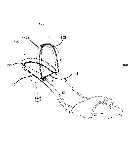
Referring to FIG. 1, an embodiment of the present invention is shown. Here,
collapsible
shoe heel 100 features support member 101, lifting member 102, and angle 103.
The support
member 101 has a first end 120 disposed opposite a second end 121. The first
end 120 of the
support member 101 has a rounded curve, as shown in FIG. 1. According to an
embodiment, the
support member 101 further includes a support structure 116 of FIG. 1
extending across the
second end 121 of the support member 101 and configured to provide additional
support to the
support member 101. It should be appreciated that the support member 101 and
the support
structure 116 are located within a sole 123 of a shoe, as depicted. It should
be appreciated that
the present invention may be integrated into any type of shoe, such as a
moccasin, a sneaker, a
dress shoe, a high heel shoe, or a sandal, among other types of shoes not
explicitly described
herein. Further, the present invention can accommodate all sizes of shoes by
varying the size of
the present invention. The present invention is suitable for use in children's
shoes, as well as
adult shoes.
The lifting member 102 of FIG. 1 has a first end 122 disposed opposite the
second end
.. 121. The first end 122 of the lifting member 102 has a rounded curve and
comprises a protrusion
section 117A (of FIG. 1) and 117B (of FIG. 3). The protrusion section 117A (of
FIG. 1) and
117B (of FIG. 3) is affixed to and is configured to protrude outward from the
first end 122 of the
lifting member 102 towards the support structure 116. The protrusion section
117A (of FIG. 1)
Date Recue/Date Received 2021-04-21
and 117B (of FIG. 3) is configured to provide a substantially flat or a flat
surface, allowing the
protrusion section 117A (of FIG. 1), 117B (of FIG. 3), and 117C (of FIG. 4) to
provide support
to a portion of a shoe being lifted by the lifting member 102. The second end
121 of the lifting
member 102 comprises the support structure 116.
Here, in FIG. 1, collapsible shoe heel 100 is shown in the natural position.
Upon
application of a compressive load at the top of the lifting member 102, the
lifting member 102
arm rotates in a downward direction as the load is applied, with the support
member 101 biased
against the bottom insole surface of the shoe, and essentially does not move.
Preferably, the
present invention operates by a person's hand squeezing against and
compressing a shoe back
which contains the lifting member 102.
Referring to FIG. 2, another embodiment of the present invention is shown. As
shown,
the collapsible shoe heel 100 also includes a first hinge 104 and a second
hinge 105. Here, the
first hinge 104 and the second hinge 105 are located within the shoe to enable
such recoverable
shoe back compression, and are torsion springs. Specifically, the first hinge
104 and the second
hinge 105 are located within the sole 123 of the shoe, as shown in FIG. 16.
The first hinge 104 rotatably connects the second end 121 of the support
member 101 and
the second end 121 of the lifting member 102. The second hinge 105 rotatably
connects the
second end 121 of the support member 101 and the second end 121 of the lifting
member 102.
Each of the first hinge 104 and the second hinge 105 are configured to define
the angle 103 (of
FIG. 1) between the second end 121 of the support member 101 and the second
end 121 of the
lifting member 102 when the lifting member 102 is in an expanded position
without an
application of force. Such expanded position is a non-compressed position. As
explained
previously, the preferred angle (e.g., the angle 103 of FIG. 1) is 30 degrees.
11
Date Recue/Date Received 2021-04-21
As the collapsible shoe heel 100 is collapsed or compressed, the angle 103
moves
towards a 0 degree angle. The support member 101 extends along the insole of
the shoe towards
the heel. Thee lifting member 102 angles up from the torsion spring to a
location at the top of the
shoe back. The downward rotation of the lifting member 102 compresses the
torsion spring.
Removal of the compressive load from the lifting member 102 initiates torsion
spring recovery.
The lifting member 102 upwardly rotates to its original position, fully
extending the shoe back.
In this regard, use of an exceedingly flexible material to fabricate the shoe
back enables multiple
compression and recovery cycles without experiencing cracking or other modes
of material
failure.
Referring to FIG. 3, an alternative embodiment of the present invention is
shown. Here,
the present invention features the support member 101, the lifting member 102,
and the
protrusion section 117B (of FIG. 3). As can be seen, support member 101 can
have a variety of
configurations, such as the configuration shown here. By varying the shape of
the support
member 101, one can vary the size and shape of the support member 101,
permitting size
adjustment to fit shoes of different sizes and styles.
Referring to FIG. 4, another alternative embodiment of the present invention
is shown.
Here, the collapsible shoe heel 100 features the lifting member 102 and an
integration member
107. The integration member 107 of FIG. 4 is located on the first end 122 of
the lifting member
102. In this embodiment, the present invention has two positions: an "up"
position and a "down"
position. This embodiment will retain whichever position it is in until some
force is exerted on
lifting member 102. When this happens, similar to the clicking of a ballpoint
pen, collapsible
shoe heel 100 will shift to the second position.
12
Date Recue/Date Received 2021-04-21
Referring to FIG. 5, the present invention features a bar 106, a slider 108,
the integration
member 107, a base 111, a first spring 114, and a second spring 115. This view
shows how this
particular embodiment functions. Specifically, upon force being applied to the
lifting member
102, the lifting member 102 will actuate the integration member 107. From
there, the integration
member 107 will push the slider 108 such that the bar 106 travels along the
notches of the slider
108. These notches are configured so that the end of the bar 106 that
interfaces with the slider
108 will move counterclockwise along the notches. The first spring 114 forces
the slider 108
towards the integrated end of the bar 106. When a user wants to toggle the
position of the present
invention, they merely need to exert force on the lifting member 102 to start
this process.
FIG. 6A, FIG. 6B, FIG. 7A, FIG. 7B, FIG. 8, and FIG. 9 depict detailed views
of the
slider 108, the base 111, the bar 106, and the integration member 107,
respectively. As shown in
FIG. 7A and FIG. 7B, the base 111 features a sliding chamber 112 and an
integration hole 113.
In a preferred embodiment, a different type of spring may be installed between
the outer
and inner shoe layers. A pair of metal extensions (such as steel) are
connected to the lifting
member 102. In a similar manner as discussed above, application of a
compressive load on the
lifting member 102 results in a bending of the lifting member 102, enabling
the lifting member
102 to lower towards the support member 101. Removal of the compressive load
enables
recovery of the lifting member 102, and the raising of the lifting member 102
to the natural
position.
In another preferred embodiment, the lifting member 102 may be fabricated out
of a
material, such as: zinc-plated steel, stainless steel, or such composite
materials, such as Nylon
6/6 Glass reinforced or ABS Glass reinforced. Utilization of the lifting
member 102 focuses flex
and recovery characteristics on the material used to fabricate the lifting
member 102, and not the
13
Date Recue/Date Received 2021-04-21
steel extensions, which would permanently deform. Substitution of differently
sized lifting
members 102 and support members 101 enables the easy adaption to shoes of
different size or
style. The extension spring design offers long-term operational and structural
stability.
In some other embodiments, the present invention is constructed with a ribbon
spring.
The spring preferably consists of a solid flat member configured into a double-
loop. The lower or
base loop would extend along the insole in the heel area of the shoe, the
upper loop extending
toward the top of the shoe back. Two substantially U-shaped segments connects
the two loops,
serving as the first hinge and second hinge of the present invention. Spring
steel or a composite
(Nylon 6/6 or ABS Glass reinforced) are materials suitable for fabricating
the ribbon spring.
In other embodiments, the present invention is constructed with a tube-spring
that utilizes
a tubular member configured into a double-loop. The lower or base loop
extending along the
back of the shoe insole, and the upper loop extending toward the top of the
shoe back. Two
substantially u-shaped segments connects the two loops, serving as the first
hinge and second
hinge of the present invention. Composite materials such as Nylon 6/6 or ABS
Glass
reinforced are suitable for fabrication of the tube spring.
In still other embodiments, the present invention consists of two U-shaped
members of
spring steel or a composite material that are connected by extendable loop
sections, serving as
the support member 101 and the lifting member.
In other examples, and as depicted in FIG. 13 and FIG. 14, the present
invention may also
comprise a first member 127 configured to be received at a first location 125
in the sole 123 of a
shoe and a second member 128 configured to be received at a second location
126 in the sole 123
of the shoe. It should be appreciated that the first location 125 differs from
the second location
126. Moreover, in examples, each of the first member 127 and the second member
128 comprise
14
Date Recue/Date Received 2021-04-21
a cloth material or a fabric material, among others not explicitly listed
herein. In some examples,
and as depicted, each of the first member 127 and the second member 128 may be
square in
shape. However, it should be appreciated that the shape of each of the first
member 127 and the
second member 128 is not limited to such.
The present invention may also include a tube portion 129 that is cylindrical
in shape,
comprising an opening disposed therein. The opening of the tube portion 129 is
configured to
receive the first end 122 of the lifting member 102, as shown in FIG. 10 and
FIG. 11. It should
be appreciated that the shape of the tube portion 129 is not limited to such
and other shapes are
contemplated. In examples, the tube portion 129 may comprise a silicone
material, among others
.. not explicitly listed herein. In some examples, the tube portion 129 may
comprise two
components (e.g., a first component 129A and a second component 129B) that
together form the
tube portion 129.
Moreover, in examples, and as depicted in FIG. 10, FIG. 11, FIG. 12, and FIG.
15, the
present invention may also include a first cylindrical portion 130 and a
second cylindrical portion
131. Each of the first cylindrical portion 130 and the second cylindrical
portion 131 comprise an
opening disposed therein. Moreover, each of the first cylindrical portion 130
and the second
cylindrical portion 131 comprise a plastic material, among others not
explicitly listed herein.
First, the first hinge 104 is received by the opening of the first cylindrical
portion 130 and
the second hinge 105 is received by the opening of the second cylindrical
portion 131. Next, a
first portion of the collapsible shoe heel 100 (e.g., the first hinge 104
received by the first
cylindrical portion 130) is received in the sole 123 of the shoe at the first
location 125 on top of
the first member 127. Then, a second portion of the collapsible shoe heel 100
(e.g., the second
hinge 105 received by the second cylindrical portion 131) is then received in
the sole 123 of the
Date Recue/Date Received 2021-04-21
shoe at the second location 126 on top of the second member 128. Doing so
affixes the
collapsible shoe heel 100 into the sole 123 of the shoe.
The descriptions of the various embodiments of the present invention have been
presented for purposes of illustration, but are not intended to be exhaustive
or limited to the
embodiments disclosed. Many modifications and variations will be apparent to
those of ordinary
skill in the art without departing from the scope and spirit of the described
embodiments. The
terminology used herein was chosen to best explain the principles of the
embodiments, the
practical application or technical improvement over technologies found in the
marketplace, or to
enable others or ordinary skill in the art to understand the embodiments
disclosed herein.
When introducing elements of the present disclosure or the embodiments
thereof, the
articles "a," "an," and "the" are intended to mean that there are one or more
of the elements.
Similarly, the adjective "another," when used to introduce an element, is
intended to mean one or
more elements. The terms "including" and "having" are intended to be inclusive
such that there
may be additional elements other than the listed elements.
Although this invention has been described with a certain degree of
particularity, it is to
be understood that the present disclosure has been made only by way of
illustration and that
numerous changes in the details of construction and arrangement of parts may
be resorted to
without departing from the spirit and the scope of the invention.
16
Date Recue/Date Received 2021-04-21