Note: Descriptions are shown in the official language in which they were submitted.
CA 03116066 2021-04-09
EMBOLISM DEVICE AND SPRING COILS THEREOF
TECHNICAL FIELD
The present invention relates to the field of medical instruments and, in
particular, an embolization device and a coil thereof for use in the treatment
of
intracranial aneurysms.
BACKGROUND
Brain aneurysms, also known as intracranial aneurysms, are a severe threat to
our health. With the development of imaging technology and biomaterials for
intravascular use, intravascular intervention has replaced surgical clipping
as the first
choice therapy for intracranial aneurysms thanks to its lower risk and less
trauma.
Presently, the treatment of an aneurysm is usually accomplished with a coil.
During embolization of the aneurysm, a corresponding shape is formed in the
aneurysm by a predetermined shape of the coil, thereby achieving a desired
embolization effect. For such treatment, the initial packing density of the
coil is one
important factor that determines long-term stability of the embolization
effect, and a
greater coil packing density can result in better clinical treatment outcomes.
Existing coils include three- and two-dimensional structures. In most cases, a
desired coil shape is made up of a combination of both particular three- and
two-dimensionally structures. The three-dimensionally structures are designed
to
build a stable frame in the lumen of an aneurysm and provide support to the
neck of
the aneurysm and the two-dimensionally ones to fill open spaces in the
aneurysm to
achieve a desired packing density. However, the three-dimensional structures
of
existing coils have a significant drawback that it is difficult for them to
achieve both
1
Date Recue/Date Received 2021-04-09
CA 03116066 2021-04-09
stable basket formation and compliant packing. For example, their constituent
elements are simple figure-eight shaped, 0-shaped or a-shaped coils, which are
difficult to compress and poorly compliant, making the coils unsuitable for
the
embolization of different aneurysms of various shapes and sizes.
SUMMARY OF THE INVENTION
In view of this, the present invention provides an embolization device and a
coil thereof with both sufficient stability and satisfactory compliance, which
can
adapt to aneurysms of different shapes and sizes and allow stable, compliant,
dense
embolization thereof.
According to one aspect of the present invention, there is proposed a coil
formed by joining together at least four structural elements arranged in
different
planes. The at least four structural elements include at least two C-shaped
elements
and at least one 0-shaped or a-shaped element, and the at least two C-shaped
elements are arranged in two adjacent planes and are sequentially joined
together to
form an S-shaped structure.
Additionally, the two adjacent planes where the S-shaped structure is arranged
may form an angle of 60 -120 .
Additionally, the angle of the two adjacent planes where the S-shaped
structure
is arranged may be 8004000
.
Additionally, the angle formed by the two adjacent planes where the S-shaped
structure is arranged may be 900
.
Additionally, in the coil, the a-shaped element may have an opening smaller
than an opening of the C-shaped element.
2
Date Recue/Date Received 2021-04-09
CA 03116066 2021-04-09
Additionally, the a-shaped element may have an arc length greater than or
equal to 75% and smaller than 100% of a complete circumference, and the C-
shaped
element may have an arc length greater than or equal to 50% and smaller than
75% of
a complete circumference.
Additionally, in the coil, the total number of the structural elements may be
six,
and the number of the C-shaped elements may be two.
Additionally, the six structural elements may make up a hexahedron having
three axes on each, and one a-shaped element is arranged on each of three axes
of the
hexahedron.
Additionally, in the coil, the coil may be formed by sequentially joining
together an 0-shaped element, a a-shaped element, one of the C-shaped
elements,
the other one of the C-shaped elements, another a-shaped element and a further
a-shaped element, which are respectively arranged in different planes.
Additionally, in the coil, the total number of the structural elements may be
eight, and the number of the C-shaped elements may be six.
Additionally, in the coil, the coil may be formed by sequentially joining
together an 0-shaped element, one of the C-shaped elements, another one of the
C-shaped elements, a further one of the C-shaped elements, a further one of
the
C-shaped elements, a further one of the C-shaped elements, the remaining one
of the
C-shaped elements and a a-shaped element, which are respectively arranged in
different planes.
Additionally, the coil may be formed by winding a tubular body.
Additionally, in the coil, the tubular body may be made of a metal, alloy or
polymer filament and is wound into a spiral.
3
Date Recue/Date Received 2021-04-09
CA 03116066 2021-04-09
According to another aspect of the present invention, there is proposed an
embolization device comprising at least one coil as defined above.
Additionally, the embolization device may include a plurality of coils,
wherein
the plurality of coils are joined together side-by-side and end-to-end , and
wherein in
any adjacent two coils, one coil is swiveled about an axis of the embolization
device
with respect to the other coil.
Additionally, in the embolization device, in any adjacent two coils, one coil
may be swiveled about the axis of the embolization device with respect to the
other
coil by an angle of 00-900
.
Additionally, in the embolization device, the structural element arranged at a
furthermost end of the embolization device is the 0-shaped element.
In the proposed embolization device and coil thereof, the coil is formed by
joining together at least four structural elements arranged in different
planes, which
include at least two C-shaped elements and at least one 0-shaped or a-shaped
element. The at least two C-shaped elements are arranged in two adjacent
planes and
sequentially joined together to form an S-shaped structure. The three-
dimensional
S-shaped structure is highly deflectable and compressive, making the coil easy
to
change its shape to adapt to different aneurysm shapes. Moreover, the a- and
0-shaped elements are highly resistant to compression and can provide strong
support
and ensure sufficient stability of the coil. With the advantages of both types
of
structural elements, the coil has both good stability and good compliance.
Therefore,
it can adapt to aneurysms of different shapes and sizes, and enables stable,
compliant,
dense embolization.
Further, the two adjacent planes where the S-shaped structure is arranged
peferably form an angle of 600-1200, with 900 more preferred. This can result
in an
4
Date Recue/Date Received 2021-04-09
CA 03116066 2021-04-09
additional increase in spatial deflectability of the S-shaped structure and
hence in
compliance of the coil.
Furthermore, the embolization device may include a plurality of coils, for
example, 2-10 coils, in which any adjacent two can be swiveled with respect to
each
other about the axis of the embolization device. This imparts higher stability
to the
embolization device, thereby resulting in an even better aneurysm embolization
effect.
BRIEF DESCRIPTION OF THE DRAWINGS
The accompanying drawings are provided for a better understanding of the
present invention and do not limit it in any way. In these figures:
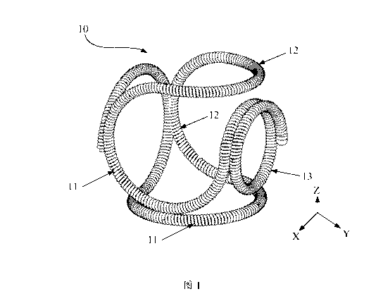
Fig. 1 is a structural schematic of a coil according to a first embodiment of
the
present invention, which is in the shape of a hexahedron;
Fig. 2 schematically illustrates a a-shaped element in the coil of Fig. 1;
Fig. 3 schematically illustrates an S-shaped structure made up of two C-shaped
elements in the coil of Fig. 1;
Fig. 4 is a simplified schematic of a coil according to a second embodiment of
the present invention, which is in the shape of a pentahedron;
Fig. 5 is a simplified schematic of an embolization device according to a
fourth
embodiment of the present invention, which includes two hexahedron-shaped
coils
not swiveled to each other;
Fig. 6 is a diagram of the embolization device of Fig. 5, in which the two
coils
are swiveled to each other;
5
Date Recue/Date Received 2021-04-09
CA 03116066 2021-04-09
Fig. 7 is a simplified schematic of the embolization device according to the
fourth embodiment of the present invention, which includes two pentahedron-
shaped
coils swiveled to each other; and
Fig. 8 is a simplified schematic of the embolization device according to the
fourth embodiment of the present invention, which includes two octahedron-
shaped
coils not swiveled to each other.
In these figures,
10, 20, 30: a coil; 11: a a-shaped element; 12: a C-shaped element; and 13: an
0-shaped element.
DETAILED DESCRIPTION
The present invention will be described in greater detail below by way of
particular embodiments with reference to the accompanying drawings. Advantages
and features of the present invention will be more apparent from the following
detailed description. Note that the figures are provided in a very simplified
form not
necessarily drawn to exact scale, and they are only intended to facilitate
convenience
and clarity in explaining the disclosed embodiments.
As used herein and in the appended claims, the singular forms "a", "an", and
"the" include plural references unless the context clearly dictates otherwise.
As used
herein and in the appended claims, the term "or" is generally employed in its
sense
including "and/or" unless the content clearly dictates otherwise. The term "C-
shaped"
is intended to refer to semicircular or similar open loops of shapes
including, but not
limited to, circular arcs, elliptical arcs, those consisting of circular arcs
with different
curvatures, and those partially linear and partially arcuate. The term "a-
shaped" is
intended to refer to an open loop with smaller openings than "C-shaped" ones.
6
Date Recue/Date Received 2021-04-09
CA 03116066 2021-04-09
Likewise, a-shaped open loops may also be of shapes including, but not limited
to,
circular arcs. The term "0-shaped" is intended to refer to closed loops of
shapes
including, but not limited to, circles, ellipses or irregular shapes. Those
skilled in the
art will recognize that the term "closed loops" is intended to refer to loops
without a
seam throughout the total length rather than those formed by bringing opposing
ends
together.
The following description sets forth numerous specific details in order to
provide a more thorough understanding of the present invention. However, it
will be
apparent to those skilled in the art that the present invention can be
practiced without
one or more of these specific details. In other instances, well-known
technical
features have not been described in order to avoid unnecessary obscuring of
the
present invention.
Before describing the present invention in detail, the primary principles and
concept of the present invention will be briefed first. A three-dimensional
coil shape
can be formed by joining together two-dimensional a-shaped structures and
three-dimensional S-shaped structures arranged in different planes. The a-
shaped
structures are structurally stable, allowing the coil to maintain good
structural stability.
At the same time, the three-dimensional S-shaped structures have good
deflectability
and compressibility, which impart high compliance to the coil. With this
construction,
the coil can achieve both stable basket formation and compliant packing and
can
adapt to various aneurysms of different shapes and sizes with a dense packing
effect.
According to embodiments of the present invention, a coil is formed by joining
together at least four structural elements arranged in different planes. The
at least four
structural elements include at least two C-shaped elements and at least one 0-
shaped
or K2-shaped element. The at least two C-shaped elements are arranged in two
7
Date Recue/Date Received 2021-04-09
CA 03116066 2021-04-09
adjacent ones of the planes and sequentially joined to form an S-shaped
structure. As
used herein, the term "0-shaped element" is meant to refer to a closed loop
structure,
which may be composed of multiple a- or C-shaped elements arranged in the same
plane of the coil. For example, an 0-shaped element may be made up of 1.5 a-
shaped
elements or 2 C-shaped elements. Both the a- and C-shaped elements are open
loop
structures, and each C-shaped element has an opening greater than the opening
of the
a- -shaped elements, and hence the C-shaped element has a higher
compressibility
than any SI-shaped one.
According to embodiments of the present invention, the coil is formed by
winding a tubular body.
<Embodiment 1>
As shown in Figs. 1 to 3, a coil 10 according to this embodiment is formed by
joining together structural elements, which are of three types and arranged in
six
planes. The structural elements include 0-, a- and C-shaped elements 13, 11,
12.
There is one 0-shaped element 13 and at least two C-shaped elements 12, and
the
total number of the 0-, a- and C-shaped elements 13, 11, 12 is six. The six
structural
elements are arranged in the respective six planes so that the coil 10
generally appears
as a hexahedron. Examples of the hexahedron are not limited to regular
hexahedrons,
parallel hexahedrons and irregular hexahedrons. In other embodiments, the six
structural elements may also be arranged in respective six planes of a
polyhedron
having at least seven planes, such as an octahedron.
The 0-, SI- and C-shaped elements 13, 11, 12 may be arranged in many ways,
as long as they satisfy several requirements including: preferred arrangement
of the
0-shaped element 13 at the furthermost end of the coil 10 (i.e., the end
farthest away
from a pusher rod), i.e., the 0-shaped element 13 being preferred to be a
leading
8
Date Recue/Date Received 2021-04-09
CA 03116066 2021-04-09
structural element in the formation of the tubular body, which can effectively
ensure
good stability of the resulting coil; and the formation of at least one three-
dimensional
S-shaped structure by two C-shaped elements 12 arranged in adjacent planes,
which
can impart increased compliance to the coil 10. As shown in Fig. 3, the two C-
shaped
elements 12 may be joined at an angle (preferably, tangentially to each
other). The
three-dimensional S-shaped structure possesses good deformation properties
including high deflectability and high compressibility, which are conducive to
increased compliance of the coil 10 and make it easier to adapt to the
embolization
requirements of different aneurysms. At the same time, the high compression
.. resistance of the SI- and 0-shaped elements 11, 13 can ensure sufficient
stability of
the coil during its stay in the lumen of the aneurysm.
It should be noted that each a-shaped element 11 has a smaller opening than
the C-shaped elements 12. In other words, each a-shaped element 11 is an open
loop
with an opening that is smaller than those of of the C-shaped elements 12.
Preferably,
.. each a-shaped element 11 has an arc length greater than or equal to 75% and
smaller
than 100% of a length of the corresponding complete circumference. Therefore,
it is
hard to compress, stable and conducive to increased stability of the coil.
Each
C-shaped element 12 has a greater opening and is preferred to have an arc
length
greater than or equal to 50% and smaller than 75% of a length of the
corresponding
complete circumference. Therefore, it is easy to compress and compliant. Thus,
incorporating both these types of structural elements allows the coil to have
both
good stability and good compliance.
In the embodiment illustrated in Fig. 1, there is one 0-shaped element 13, two
C-shaped elements 12 and three a-shaped elements 11 in the coil 10, which are
sequentially joined together in the following sequence: the 0-shaped element
13, one
9
Date Recue/Date Received 2021-04-09
CA 03116066 2021-04-09
of the a-shaped elements 11, one of the C-shaped elements 12, the other one of
the
C-shaped elements 12, another one of the a-shaped elements 11 and the
remaining
one of the a-shaped elements 11. One of the C-shaped elements 12 may be
arranged
at a top side of the hexahedron, and the other C-shaped element 12 may be
arranged
at a rear side of the hexahedron, i.e., the furthermost side as viewed in Fig.
1. This
arrangement is advantageous in that the three a-shaped elements 11 are
arranged on
respective axes of the hexahedron, with one 0-shaped element being arranged on
one
of the axes. This can ensure good stability of the coil 10, in addition to
good overall
compliance thereof assured by the three-dimensional S-shaped structure.
Preferably, the two adjacent planes where the S-shaped structure is arranged
form an angle of 600-1200. In some embodiments, the angle of the two adjacent
planes where the S-shaped structure is arranged may be 800-1000. In some
embodiments, the angle of the two adjacent planes where the S-shaped structure
is
arranged may be 80 , 90 or 100 . In addition, in the case of the angle of the
two
adjacent planes where the S-shaped structure is arranged being 90 , the S-
shaped
structure will have the highest deflectability in the three-dimensional space,
resulting
in better compliance of the coil 10.
Apart from the above-described construction, in alternative embodiments, the
coil 10 may be constructed by joining together one 0-shaped element 13, three
C-shaped elements 12 and two a-shaped elements 11 sequentially in the
following
order: the 0-shaped element 13, one of the a-shaped elements 11, one of the
C-shaped elements 12, another one of the C-shaped elements 12, the other one
of the
a-shaped elements 11 and the remaining one of the C-shaped elements 12. In yet
alternative embodiments, the coil 10 may be constructed by joining together
one
0-shaped element 13, four C-shaped elements 12 and one a-shaped element 11
Date Recue/Date Received 2021-04-09
CA 03116066 2021-04-09
sequentially in the following order: the 0-shaped element 13, the a-shaped
element
11, one of the C-shaped elements 12, another one of the C-shaped elements 12,
a
further one of the C-shaped elements 12 and the remaining one of the C-shaped
elements 12. In still alternative embodiments, the coil 10 may be constructed
by
joining together one 0-shaped element 13, three C-shaped elements 12 and two
Q-shaped elements 11 sequentially in the following order: the 0-shaped element
13,
one of the C-shaped elements 12, another one of the C-shaped elements 12, one
of the
Q-shaped elements 11, the other one of the a-shaped elements 11 and the
remaining
one of the C-shaped elements 12. It would be appreciated that, in case of an
odd
number of C-shaped elements 12, e.g., three C-shaped elements 12, since each
C-shaped element 12 has a greater opening than those of the a-shaped elements
11,
the greater the number of the C-shaped elements 12 is, the better the
deformability of
the coil 10 will be.
In general, the hexahedron may have three axes, e.g., the X, Y and Z axes as
shown in Fig. 1. In case of a regular hexahedron, the three axes are
orthogonal to one
another. In order to achieve both good stability and sufficient compliance, in
addition
to forming one S-shaped structure by arranging respective C-shaped elements 12
in
two adjacent ones of the planes, it is preferred that in each pair of opposing
ones of
the planes, which are both perpendicular to a corresponding one of the axes,
one
Q-shaped element 11 and one C-shaped element 12 are respectively arranged.
Specifically, when the embolization device includes only one coil 10, or when
the coil
10 is arranged at the furthermost (or closest) end of the embolization device,
it is
preferred that the leading first element (or the trailing element, in case of
the coil 10
is arranged at the closest end) is a closed loop, in order to ensure that the
embolization device has sufficient stability at said end. In other instances,
the
11
Date Recue/Date Received 2021-04-09
CA 03116066 2021-04-09
0-shaped element 13 may be replaced with a a-shaped element 11, or the 0-
shaped
element 13 may not be the leading element. Additionally, the coil 10 may
include
more than one 0-shaped element 13. The 0-shaped element 13 is a spiral
structure
formed by winding the tubular body of the coil. As used herein, the term
"spiral
structure" can be interpreted to refer to a structure consisting of multiple
SI- or
C-shaped elements 11, 12 of the same or different diameters, such as a
structure
consisting of 1.5 a-shaped elements 11 as shown in Fig. 1. The closed loop can
increase stability of the coil.
Further, the hexahedron is preferred to have an angle of 90 between each pair
of planes where two corresponding adjacent ones of the elements are arranged.
The
hexahedron is preferably a regular hexahedron, i.e., a cube. Those skilled in
the art
may make suitable modifications to the foregoing element arrangements in light
of
the teachings herein to obtain coils 10 with different element arrangements,
which are,
however, intended to also fall within the scope of the invention.
<Embodiment 2>
As shown in Fig. 4, a coil 20 according to this embodiment is formed by
joining together structural elements, which are of three types and arranged in
five
planes. Similarly, the structural elements include 0-, a- and C-shaped
elements 13,
11, 12. There is one 0-shaped element 13 and at least two C-shaped elements
12, and
the total number of the 0-, SI- and C-shaped elements 13, 11, 12 is five. The
five
structural elements are arranged in the respective five planes to achieve a
coil 20 with
a pentahedron structure. Herein, the coil 20 appears as a pentahedron. In
other
embodiments, the five structural elements may also be arranged in respective
five
planes of a polyhedron having at least six planes, such as a hexahedron.
12
Date Recue/Date Received 2021-04-09
CA 03116066 2021-04-09
In the pentahedron, the 0-, SI- and C-shaped elements 13, 11, 12 may also be
arranged in many ways, and the arrangement may follow substantially the same
requirements as Embodiment 1. A further detailed description of how they are
arranged with be set forth below.
In one embodiment, the coil 20 may be constructed by joining together one
0-shaped element 13, two C-shaped elements 12 and two a-shaped elements 11
sequentially in the following order: the 0-shaped element 13, one of the a-
shaped
elements 11, one of the C-shaped elements 12, the other one of the C-shaped
elements
12 and the other one of the a-shaped elements 11. One of the C-shaped elements
12
may be arranged at a top side of the pentahedron, and the other C-shaped
element 12
may be arranged at a rear side of the pentahedron, i.e., the furthermost side
as viewed
in Fig. 4. In order to achieve higher deflectability of the S-shaped
structure, the top
side preferably forms an angle of 90 with the lateral side. In this
arrangement, on
each of three axes of the pentahedron, there is arranged one a-shaped element
11 or
0-shaped element 13. This can ensure good stability of the coil 20, in
addition to
good overall compliance thereof assured by the three-dimensional S-shaped
structure.
Each lateral side of the pentahedron is preferably perpendicular to both
bottom and
top sides of the pentahedron, while angles between the lateral sides are not
limited to
any particular value. Two adjacent ones of the lateral sides may form an angle
of 90 .
In alternative embodiments, the coil 20 may be constructed by joining together
one 0-shaped element 13, two C-shaped elements 12 and two a-shaped elements 11
sequentially in the following order: the 0-shaped element 13, one of the C-
shaped
elements 12, the other one of the C-shaped elements 12, one of the a-shaped
elements 11 and the other one of the a-shaped elements 11. In yet alternative
embodiments, the coil 20 may be constructed by joining together one 0-shaped
13
Date Recue/Date Received 2021-04-09
CA 03116066 2021-04-09
element 13, three C-shaped elements 12 and one a-shaped element 11
sequentially in
the following order: the 0-shaped element 13, one of the C-shaped elements 12,
another one of the C-shaped elements 12, the remaining one of the C-shaped
elements
12 and the a-shaped element 11. In still alternative embodiments, the coil 20
may be
constructed by joining together one 0-shaped element 13, three C-shaped
elements
12 and one a-shaped element 11 sequentially in the following order: the 0-
shaped
element 13, the a-shaped element 11, one of the C-shaped elements 12, another
one
of the C-shaped elements 12 and the remaining one of the C-shaped elements 12.
Similarly, those skilled in the art may make suitable modifications to the
foregoing element arrangements in light of the teachings herein to obtain
coils 20
with different element arrangements, which are, however, intended to also fall
within
the scope of the invention. Moreover, in this embodiment, the 0-shaped element
13
may be replaced with a a-shaped element 11, or may not be the leading element,
unless it is arranged at the furthermost or closest end of the embolization
device.
Moreover, the coil may include more than one 0-shaped element 13.
<Embodiment 3>
A coil 30 according to this embodiment is formed by joining together
structural
elements, which are of three types and arranged in eight planes. Similarly,
the
structural elements include 0-, a- and C-shaped elements 13, 11, 12. There is
one
0-shaped element 13 and at least two C-shaped elements 12, and the total
number of
the 0-, a- and C-shaped elements 13, 11, 12 is eight. The eight structural
elements
are arranged in the respective eight planes to achieve a coil 30 of an
octahedron
structure. Herein, the coil 30 generally appears as an octahedron. The
octahedron is
not limited to a regular octahedron, as long as the structural elements are
arranged in
respective eight planes of a polyhedron.
14
Date Recue/Date Received 2021-04-09
CA 03116066 2021-04-09
In the octahedron, the 0-, SI- and C-shaped elements 13, 11, 12 may also be
arranged in many ways, and the arrangement may follow substantially the same
requirements as Embodiment 1. A further detailed description of how they are
arranged with be set forth below.
In a preferred embodiment, the coil 30 may be constructed by joining together
one 0-shaped element 13, six C-shaped elements 12 and one a-shaped element 11
sequentially in the following order: the 0-shaped element 13, one of the C-
shaped
elements 12, another one of the C-shaped elements 12, a further one of the C-
shaped
elements 12, a further one of the C-shaped elements 12, a further one of the C-
shaped
elements 12, the remaining one of the C-shaped elements 12 and the a-shaped
element 11. Each adjacent pair of the C-shaped elements 12 is arranged at a
respective adjacent pair of the planes, and each adjacent pair of the planes
where a
respective adjacent pair of the C-shaped elements 12 is arranged may form an
angle
in the range of 100 -120 , with 109 -110 being more preferred. In an
alternative
embodiment, the coil 30 may be constructed by joining together one 0-shaped
element 13, five C-shaped elements 12 and two a-shaped elements 11
sequentially in
the following order: the 0-shaped element 13, one of the a-shaped elements 11,
one
of the C-shaped elements 12, another one of the C-shaped elements 12, a
further one
of the C-shaped elements 12, a further one of the C-shaped elements 12, the
remaining one of the C-shaped elements 12 and the other one of the a-shaped
elements 11, or in the following order: the 0-shaped element 13, one of the C-
shaped
elements 12, another one of the C-shaped elements 12, a further one of the C-
shaped
elements 12, the other one of the a-shaped elements 11, a further one of the C-
shaped
elements 12, a further one of the C-shaped elements 12 and the remaining one
of the
C-shaped elements 12.
Date Recue/Date Received 2021-04-09
CA 03116066 2021-04-09
In this embodiment, the coil 30 is more compliant because it contains more
C-shaped elements 12. Compared to the hexahedron or pentahedron, the
octahedron
has more planes where the additional C-shaped elements 12 can be arranged,
which
result in an increase in the coil's compliance.
Of course, the present invention is not limited to the above arrangements, and
those skilled in the art may modify the above description by making
appropriate
modification to the details therein so that the modified description is
applicable to
coils with different arrangements. Similar to Embodiments 1-2, the 0-shaped
element
13 may be replaced with a a-shaped element 11, or may not be the leading
element,
unless it is arranged at the furthermost or closest end of the embolization
device.
Moreover, the coil may include more than one 0-shaped element 13.
While the pentahedron, hexahedron and octahedron-shaped coils are proposed
in Embodiments 1 to 3, the present invention is not limited thereto, because
other
polyhedron shapes with more planes in which additional C-shaped elements can
be
arranged to result in a further increase in the coil's compliance are also
possible.
According to the present invention, a coil must consist of at least four
structural
elements, which are joined together and arranged in four planes of a
polyhedron.
Further, C-shaped elements in a single coil may have either the same or
different sizes, for example, in terms of diameter or arc length, and when
there are
multiple a-shaped elements, they may have either the same or different sizes.
In one
embodiment, the tubular body of the coil may be formed as a primary coil by
densely
winding a platinum tungsten alloy filament with a diameter ranging from 0.001
inch
to 0.0035 inches onto a metal core rod with a diameter of 0.008 inches. After
that, the
primary coil (i.e., the tubular body) may be shaped with the predetermined
shape so
16
Date Recue/Date Received 2021-04-09
CA 03116066 2021-04-09
as to form a coil with polyhedron shape consisting of mutually joined 0-, S2-
and
S-shaped structural elements.
<Embodiment 4>
An embolization device according to this embodiment includes the coils 10, 20
or 30 of Embodiment 1-3 for treatment of an aneurysm by thrombus formation in
the
lumen of the aneurysm. In Embodiment 4, including at least one coil,
preferably
multiple coils, the multiple coils may be joined together side-by-side and end-
to-end
in such a manner that in any adjacent pair of the coils, one is swiveled about
an axis
of the embolization device with respect to the other. With this design, the
embolization device has improved stability in various directions, resulting in
an
increase in overall stability of the embolization device. The embolization
device can
fill the lumen of the aneurysm in different planes, thus achieving even
packing
thereof. Further, the swivel ability means increased compliance of the
embolization
device. The physician may select alternative configurations of the
embolization
device suitable for the shapes and sizes of particular aneurysms.
As shown in Fig. 5, the embolization device may be a combination of two or
more coils 10, and in any two of the coils 10, one may be swiveled about the
axis of
the embolization device at an angle of preferably 0 -90 , more preferably 30 ,
45 ,
60 or 90 . This allows the embolization device to have increased overall
stability and
enhanced compliance. It should be noted that the two coils 10 may be formed
from a
single coil tubular body made by coiling a metal, alloy or polymer filament
into a
spiral (i.e., the primary coil). Fig. 6 is a simplified schematic of two
hexahedron-shaped coils 10 which are swiveled with respect to each other, and
Fig. 7
is a simplified schematic of two pentahedron-shaped coils 20 which are also
swiveled
with respect to each other. Apparently, compared with those consisting of
single coil,
17
Date Recue/Date Received 2021-04-09
CA 03116066 2021-04-09
the embolization device constructed from two or more mutually swiveled coils
20 has
higher stability and better dense packing performance. Similarly, as shown in
Fig. 8,
the embolization device may also be made up of a combination of two or more
octahedron-shaped coils 30. In Fig. 8, for easier illustration, the octahedron-
shaped
coils 30 are depicted in a simplified manner.
In this embodiment, the side-by-side arranged coils 10 may be of the same or
different sizes and shapes. While the two coils 10 are shown in Fig. 5 to have
different structures, the present invention is not limited to this.
In summary, in embolization devices and coils thereof according to
embodiments of the present invention, each coil is formed by joining together
at least
four structural elements arranged in different planes, which include at least
two
C-shaped elements and at least one 0-shaped or a-shaped element. The at least
two
C-shaped elements arranged in two adjacent ones of the planes and sequentially
joined together to form an S-shaped structure. The S-shaped structure is
highly
deflectable and compressive, making the coil easy to change its shape to adapt
to
different aneurysm shapes. Moreover, the a- and 0-shaped elements are highly
resistant to compression and can provide strong support and ensure sufficient
stability
of coil, making the coil adaptive to aneurysms of different shapes and sizes.
All of
these make the coil enables stable, compliant, dense embolization. In
addition, each
embolization device may include plurality of coils, for example, 2-10 coils,
in which
any adjacent two can be swiveled with respect to each other about an axis of
the
embolization device. This allows not only improved packing compliance of the
embolization device but also higher overall stability of the packed
embolization
device, resulting in an even better aneurysm embolization effect.
18
Date Recue/Date Received 2021-04-09
CA 03116066 2021-04-09
The embodiments disclosed herein are described in a progressive manner, with
the description of each embodiment focusing on its differences from others.
Reference can be made between the embodiments for their identical or similar
parts.
The description presented above is merely that of some preferred embodiments
of the present invention and does not limit the scope thereof in any sense.
Any and all
changes and modifications made by those of ordinary skill in the art based on
the
above teachings fall within the scope as defined in the appended claims.
19
Date Recue/Date Received 2021-04-09