Note: Descriptions are shown in the official language in which they were submitted.
CA 03117101 2021-04-19
1
GAS APPLIANCE IGNITION MODULE
CROSS-REFERENCE TO RELATED APPLICATIONS
[0001] This application claims priority to U.S. Provisional Patent Application
Serial No.
62/747,365, entitled MODULAR ELEC1RICAL CONNECTOR, filed October 18, 2018.
BACKGROUND
[0002] Gas appliances, such as gas grills and other cooking devices, often
utilize ignitors
mounted onto the appliance. Some are powered by a power source, such one or
more batteries,
and such devices typically comprise a control module to control the ignition
source. An ignition
module can comprise or be coupled with an actuator switch, used by a user, and
one or more
ignitors, for igniting the fuel. The module itself is often mounted on the
appliance, and it can be
mounted in a variety ways. For example, some modules have the actuator switch
engaged with
the module, while others have a connector, such as a wire, leading from the
switch to a remotely
mounted module. Modules with the actuator switch, such as a button, directly
engaged with the
module typically utilize a battery compartment that protrudes through the
panel of the appliance
to which the module is mounted. hi any event the battery within the module can
provide
electrical power to an electronic circuit therein in order to generate a
voltage potential. If the
voltage is applied to an electrode (e.g., in the ignitor), and the voltage is
sufficiently large
enough, the air across a gap on the electrode will be ionized and a spark will
be generated,
thereby enabling an air/gas mixture surrounding the gap to be ignited.
SUMMARY
[0003] This Summary is provided to introduce a selection of concepts in a
simplified form
that are further described below in the Detailed Description. This Summary is
not intended to
Date Recue/Date Received 2021-04-19
CA 03117101 2021-04-19
2
identify key factors or essential features of the claimed subject matter, nor
is it intended to be
used to limit the scope of the claimed subject matter.
[0004] As provided herein, an ignition control module for a gas appliance
can be devised that
provide for controlling an ignition source for the gas appliance, such as when
an ignition actuator
switch is activated by a user of the appliance. The ignition control module
can be configured to
provide for ease of installation and use by providing improved connection
points for respective
ignitor connectors and/or actuator switch connection. Further, the ignition
control module can be
configured to provide for mitigating exposure to potential contaminants, such
as introduced by
accident, environmental condition, during use, and/or battery material
leakage. For example, the
battery can be disposed in a position that reduces potential damage from
leaks; and the
connection points can be protect from exposure.
[0005] In one implementation, an exemplary ignition module for use on a gas
appliance can
comprise a base housing. The base housing can be configured to be fixedly
mounted on the gas
appliance. Further, the exemplary ignition module can comprise a battery
compartment that is
engaged with the base housing. The battery compartment can be configured to
hold a battery in
its operable position when the base housing is mounted for operation on the
gas appliance.
Additionally, when the module is mounted for operation, the battery
compartment can be
configured to dispose the battery's negative terminal at a lower elevation
than the battery's
positive terminal. The battery compaitinent can comprise a battery access
portion that operates
to selectably access the battery compaitnient, such as to install or remove a
battery.
[0006] In another implementation, an exemplary device for controlling an
ignition source in a
gas appliance can comprise a housing. The housing can be configured to
enclose, at least
partially, one or more control components disposed therein. Further, the
exemplary device for
controlling an ignition source in a gas appliance can comprise one or more
ignitor terminals that
are engaged with the housing. The one or more ignitor terminals can
respectively comprise an
ignitor terminal connector that is configured to selectably, operably couple
with a corresponding
ignitor connector.
[0007] In another implementation, an exemplary device for controlling an
ignition source in a
gas appliance can comprise an activation module. The activation module can
comprise a low
profile that is also weather resistant. The activation module can selectably
engage with a target
Date Recue/Date Received 2021-04-19
CA 03117101 2021-04-19
3
grill and with the ignition module. Activating the activation module can close
a circuit that
results in electrical power from a battery in the ignition module being
provided to one or more
ignitors coupled with the ignition module.
[0008] In another implementation, a gas appliance ignition apparatus can
comprise a housing.
The housing can be configured to enclose, at least partially, one or more
control components
disposed therein. Further, the exemplary device for controlling an ignition
source in a gas
appliance can comprise one or more ignitor terminals that are engaged with the
housing.
Additionally, the exemplary device for controlling an ignition source in a gas
appliance can
comprise an ignitor actuator terminal that is engaged with the apparatus
housing. The ignitor
actuator terminal can be configured to selectably engage with an ignitor
actuator connector. The
ignitor actuator terminal can comprise an ignitor actuator terminal connector
that comprises at
least two terminal electrical connection points. The ignitor actuator terminal
can also comprise
an ignitor actuator terminal housing that is configured to selectably receive
the ignitor actuator
connector. The ignitor actuator terminal housing receiving the ignitor
actuator connector can
result in an electrical connection between the ignition apparatus and an
ignitor actuator.
[0009] To the accomplishment of the foregoing and related ends, the
following description
and annexed drawings set forth certain illustrative aspects and
implementations. These are
indicative of but a few of the various ways in which one or more aspects may
be employed.
Other aspects, advantages and novel features of the disclosure will become
apparent from the
following detailed description when considered in conjunction with the annexed
drawings.
BRIEF DESCRIPTION OF THE DRAWINGS
[0010] What is disclosed herein may take physical form in certain parts and
arrangement of
parts, and will be described in detail in this specification and illustrated
in the accompanying
drawings which form a part hereof and wherein:
[0011] FIGURES 1A, 1B, 1C, and ID are components diagram illustrating
various viewsof
an exemplary ignition control module in accordance with one or more devices
described herein.
Date Recue/Date Received 2021-04-19
CA 03117101 2021-04-19
WO 2020/081921 PCT/US2019/056911
4
[0012] FIGURE 2 is a component diagram illustrating a top perspective view
of one or more
exemplary ignitor couplings in accordance with one or more devices described
herein.
[0013] FIGURES 3A, 3B, and 3C are component diagrams illustrating various
cut-away
views of an exemplary ignitor coupling in accordance with one or more devices
described herein.
[0014] FIGURES 4A and 4B are component diagrams illustrating various views
of an
implementations of an activator module as described herein.
[0015] FIGURES 5A and 5B are component diagrams illustrating various cut-
away views of
an implementations of an activator module as described herein.
[0016] FIGURE 6 is a component diagram illustrating an alternate
implementation of a spark
system for improving ease of assembly of connections on a spark generator.
DETAILED DESCRIPTION
[0017] The claimed subject matter is now described with reference to the
drawings, wherein
like reference numerals are generally used to refer to like elements
throughout. In the following
description, for purposes of explanation, numerous specific details are set
forth in order to
provide a thorough understanding of the claimed subject matter. It may be
evident, however,
that the claimed subject matter may be practiced without these specific
details. In other
instances, structures and devices may be shown in block diagram form in order
to facilitate
describing the claimed subject matter.
[0018] The tei in "gas," as in gas appliance or gas grill, or a gas fuel
used in said systems, may
be used in furtherance of disclosure of the details of the claimed ignition
module device or
apparatus. It should be noted that the term "gas" may refer to a flammable
gas, such as propane,
natural gas, or the like; and/or a flammable mixture of air and vapors or air
entrained droplets of
a flammable liquid, such as kerosene, lighter fluid, or the like; or any such
combination. In
general, the term "gas" can refer to a fuel used in a gas appliance of any
kind.
[0019] As described herein, an ignition module device or apparatus may be
devised for
installation on a gas appliance, such as a gas grill or the like, for example.
In one
implementation, such an ignition module can be configured to use a battery as
a power source to
provide an ignition source, such as a spark, upon actuation, such as by a user
of the gas
CA 03117101 2021-04-19
WO 2020/081921 PCT/US2019/056911
appliance. For example, a gas appliance (e.g., gas grill) may comprise an
actuator switch (e.g.,
button) coupled with the ignition module. Activating the switch (e.g.,
pressed) can result in the
ignition module sending an electrical charge to a coupled ignitor, disposed
proximate a gas
burner. In this example, the electrical charge sent to the ignitor can result
in a spark, which acts
as the ignition source to ignite gas released from the burner. In one
implementation, such a
device can be installed on a gas appliance that is subjected to environmental
conditions which
can result in a shortened life for the module. In this implementation, an
example ignition module
may comprise a configuration that mitigates exposure to deleterious
environmental conditions,
and/or is configured to provide for extended life when exposed to such
conditions.
[0020] In one implementation, an exemplary ignition module can comprise a
base housing
that is configured to be fixedly mounted on a gas appliance surface. As an
example, an ignition
module may be mounted on an under surface of a gas grill, such as proximate
the burner
controls, ignition switch, and/or under the grill cooking area itself;
usually, at least partially
covered by a portion of the grill (e.g., shelf, cover, control mounting
surface, etc.). In one
implementation, as illustrated in the base housing can be mounted on a gas
appliance vertical
surface.
[0021] The exemplary ignition module can comprise a battery compartment
that is engaged
with the base housing. The battery compartment can be configured to hold a
battery in its
operable position, such as during use, when mounted on the gas appliance, for
example. Further,
the battery compartment can be configured to dispose the battery's negative
terminal at a lower
elevation than the battery's positive terminal, when the base housing is
mounted for operation on
the gas appliance surface.
[0022] As one example, the battery compartment can hold a battery
comprising a negative
terminal and a positive terminal. In one or more implementations, as
illustrated in when the
example ignition module is mounted in an operable position, the central axis
of the battery
compartment can be disposed at angle from a vertex point at the mounting
surface that provides a
downward slope from horizontal. That is, for example, the battery compartment
slopes
downward toward the distal end. In this way, in this implementation, the
negative terminal of
the battery can be disposed at a lower elevation than the positive terminal.
CA 03117101 2021-04-19
WO 2020/081921 PCT/US2019/056911
6
[0023] Commonly, batteries comprise a design that disposes the negative
telminal at a first
end/side of the battery, and the positive terminal at a second, opposing
end/side of the battery.
Further, some batteries (e.g., cylindrical style) are formed with a tube
portion and a cap, where
the tube portion contains a substantive portion of the electro-chemical
materials, and the cap
seals the end of the tube to mitigate leakage of chemicals. Typically, the
closed end of the tube
portion comprises the positive terminal, and the cap comprises the negative
terminal of the
battery. For this reason, for example, when leakage occurs from a battery, it
typically occurs
proximate the negative terminal, as the cap is a potential weak point in the
battery's seal.
Materials leaked from a battery can comprise corrosive chemicals that often
result in damage to
the equipment utilizing the battery. Therefore, disposing the negative
terminal of the battery at a
lower elevation than the positive terminal may limit exposure to potentially
leaked materials to
merely the negative terminal end of the battery.
[0024] In one implementation, the battery compartment can comprise a
battery access portion,
disposed at a first end of the battery compartment. The battery access portion
can be operable to
selectably access the battery compartment. For example, devices that utilize
batteries typically
comprise an access point for installing and/or replacing batteries,
particularly if there is no means
for recharging a battery in place, in the device. A battery compartment access
can comprise a
variety of designs that are selected, based on suitability for the intended
purpose of the host
device. For example, for an ignition control module, the battery access
portion may be readily
accessible, and provide for ease of use, as the module may be mounted in a
location that is not
easily accessed (e.g., hidden behind an appliance partition or component).
[0025] In this implementation, the battery access portion may comprise a
graspable surface;
and, in conjunction with a body portion 134disposed at a second end of the
battery compartment,
can comprise an engagement component that allows the battery access portion to
be selectably
opened and closed. As an example, the battery access portion may be selectably
engaged with
the body portion of the battery compartment using a threaded fitting,
clasp(s), fastener(s), clip, or
other similar means, with or without a hinge apparatus. The body portion of
the battery
compartment may be removed from the body portion of the battery compartment,
or the battery
compartment may remain, at least partially, engaged with the body portion of
the battery
compartment, such as by use of a hinge-like mechanism.
CA 03117101 2021-04-19
WO 2020/081921 PCT/US2019/056911
7
[0026] In one implementation, the battery access portion may comprise a cap
that can be
engaged with the body portion of the battery compartment, where the battery
compartment
projects from the housing of an example module. It should be noted that,
although the example
implementations illustrated disclose the battery compartment projecting from
the base housing
orthogonally from a longitudinal axis of the base housing, it is anticipated
that alternate
implementations may be devised by those skilled in the art For example, the
central axis of the
battery compartment may be disposed in parallel with the central or
longitudinal axis of the base
housing; or the central axis of the battery compartment may be disposed in
parallel with the
lateral axis of the base housing. In these examples, the module can be mounted
on the appliance
surface in such a manner that provide for the negative terminal of the battery
being disposed at a
lower elevation than the positive terminal.
[0027] In one implementation, the battery access portion of the battery
compartment can
comprise a negative electrical contact terminal for the ignition module. In
this implementation, a
positive electrical contact terminal for the ignition module can be fixedly
disposed at an
opposing end of the battery compartment, such as in the battery compartment
body portion. That
is, for example, the battery compartment can comprise a cylindrically shaped
tube for holding a
cylindrically shaped battery (e.g., AA, AAA, C, D sized), with its terminals
disposed at opposite
ends. In this example, the negative electrical contact terminal, for
contacting the battery's
negative terminal, can be in the access end of the battery compartment, such
as in a cap-shaped
battery access portion. Additionally, the positive electrical contact terminal
can be disposed at
the other end of the battery compartment, such as in the body portion,
[0028] In one implementation, the body portion, comprising the positive
electrical contact
terminal, can be proximate (e.g., and fixedly engaged with) the base housing
102Further, the
negative electrical contact terminal can be disposed in the battery access
portion, for example,
which may protrude away from the base housing. Additionally, the base housing
can comprise
the ignition control module, for example, which may comprise circuits,
processors, and/or other
electrical components, used to control electrical signals sent to one or more
ignitors used in the
gas appliance. In this implementation, disposing the negative electrical
contact terminal, and
therefore the battery's negative terminal, away from the ignition control
module 72 may mitigate
leaked material from the battery potentially contacting the ignition control
module.
CA 03117101 2021-04-19
WO 2020/081921 PCT/US2019/056911
8
[0029] That is, for example, when the ignition module is operably mounted
on the gas
appliance, the battery's negative terminal is disposed at a lower elevation
than the battery's
positive terminal. In this example, resulting leaked material (e.g., likely
leaked from the
battery's negative terminal) will flow down, away from the positive electrical
contact terminal
706, and therefore, away from the ignition control module. In this way,
potential damage to the
ignition control module resulting from corrosive battery material, for
example, may be mitigated.
[0030] In one implementation, the battery access portion can comprise a
selectably removable
cap that is configured to collect material leaked from a battery disposed in
the battery
compartment. For example, as described above, material may leak from the
battery (e.g.,
typically at the negative terminal end); and, when the negative terminal is
disposed at a lower
elevation than the positive terminal, the leaked battery material may flow
downward toward the
negative end. In this example, the negative electrical contact terminal can be
disposed in the
cap-shaped battery access portion, which may collect any leaked material from
the battery. In
this way, for example, if one or more portions of the cap-shaped battery
access portion are
damaged due to exposure to the leaked (e.g., corrosive) battery material, the
cap may simply be
replaced (e.g., or cleaned), instead of replacing more expensive portions
(e.g., or all) of the
ignition module.
[0031] In one implementation, the battery access portion can comprise an
electrical coupler
that is configured to electrically couple the negative electrical contact
terminal in the battery
access portion with the ignition control module when the battery access
portion is selectably
engaged with the body portion of the battery compartment. That is, for
example, the battery
access portion may be configured to be selectably removed from the battery
compartment, and
selectably re-engaged with the battery compartment. In this implementation,
for example, the
negative electrical contact terminal can be electrically coupled with a first
portion (e.g., a wire,
such in a spring shape, or other electric al contact) of the electrical
coupler, disposed in the
battery access portion, and a second portion of the electrical coupler can be
disposed in the body
portion of the battery compartment. In this implementation, when the battery
access portion
(e.g., cap) is engaged with the body portion, the first portion of the
electrical coupler may
electrically couple with the second portion of the electrical coupler. In this
way, for example, the
negative electrical contact terminal can be in electrical coupling with the
ignition control module
when the battery access portion is engaged with the body portion of the
battery compartment.
CA 03117101 2021-04-19
WO 2020/081921 PCT/US2019/056911
9
[0032] In one implementation, the example module can comprise a gasket
disposed on the
battery compartment. In this implementation, the gasket can be disposed
between the battery
access portion and the body potion of the battery compartment, and be
configured to engage with
the battery access portion to mitigate migration of contaminants between the
outside and inside
of the battery compartment. That is, for example, the gasket may mitigate
entry of
environmental contaminants (e.g., water, dust, dirt, grease, food or other
particles) into the
battery compartment. Further, the gasket may mitigate leaked battery materials
from flowing out
of the battery compartment.
[0033] In one aspect, the example ignition module can be mounted on a gas
appliance, such
as on a vertical surface of the appliance. In one implementation, in this
aspect, the base housing
can comprise one or more module mounting point components that are
respectively configured
to be used to mount the base housing on a vertical surface of the appliance.
In this
implementation, the one or more module mounting point components are
configured to mount
the base housing such that a first end of the battery compartment, comprising
the battery access
portion, is disposed at a lower elevation than an opposing, second end of the
battery
compartment, comprising the body portion. That is, for example, the mounting
point
components, when mounted, may dispose the battery compartment, and/or the base
housing
engaged with the battery compartment, at angle that provides a downward slope
to the battery
compartment. In this way, in this example, any fluids leaked from a battery in
the battery
compartment can flow down toward the distal end of the battery compartment.
[0034] In one implementation, the one or more module mounting point
components can
comprise a first module mounting foot and a second module mounting foot. In
this
implementation, the second module mounting foot can comprise a greater
thickness than the
thickness of the first module mounting foot. In this implementation, the
measured thickness for
the respective feet, can be measured from a mounting surface of the respective
module mounting
feet. As an example, when the ignition module is mounted on a gas appliance
vertical surface a
first end of the module may be disposed below a second end of the module. In
this example, the
first mounting foot may also be disposed below the second mounting foot. For
example, the
greater thickness of the second mounting foot, when compared to the thickness
of the first
mounting foot, can dispose the battery compartment at a downward slope, as
described above,
when the feet are mounted to the vertical surface.
CA 03117101 2021-04-19
WO 2020/081921 PCT/US2019/056911
[0035] In one implementation, the respective mounting points can comprise
an aperture. That
is, the first mounting point can comprise a first aperture, and the second
mounting point can
comprise a second aperture (e.g., and a third mounting point, if present, can
comprise a third
aperture, and so on). In this implementation, the respective apertures may be
used to receive a
fastener (e.g., a screw, bolt, pin, or the like) that can secure the base
housing to the gas appliance,
such as at the vertical surface. Additionally, the respective mounting points
can comprise one or
more supports. That is, the first mounting point can comprise a first (set of)
support(s), and the
second mounting point can comprise a second (set of) support(s) (e.g., and a
third mounting
point, if present, can comprise a third (set of) support(s), and so on). In
this implementation, the
respective supports may provide additional support to the respective mounting
points, by
coupling with the base housing.
[0036] In an alternate implementation, an exemplary ignition module can
comprise an
alternate mounting design. In this implementation, a bottom surface of the
module may
comprise a plane with a longitudinal axis that is not parallel to the
longitudinal axis of the
module; such that, when mounted to a vertical surface that is parallel to the
longitudinal axis of
the module, the battery compartment is disposed at a downward slope toward its
distal end. That
is, for example, the bottom of the base housing is sloped so that when the
base housing is
mounted on the vertical surface, the module is angled downward.
[0037] Another implementation, an exemplary ignition module, can comprise
alternate
mounting design. In this implementation, the exemplary ignition module may be
mounted on a
vertical surface (e.g., having a vertical Y axis) with the ignition module's
longitudinal axis lying
horizontally (e.g., in the X axis) across the vertical surface (e.g., mounted
horizontally on the
vertical surface). In this implementation, the first mounting point and the
second mounting point
can respectively comprise a leading end and a trailing end. The leading end
can comprise a
thickness that is greater than a thickness "of the trailing end. In this
configuration, in this
implementation, the exemplary ignition module can be configured to be mounted
in a horizontal
configuration on the vertical surface. In this way, for example, the housing
base, and the
engaged battery compartment, can tilt at a downward slope when mounted on the
vertical
surface.
CA 03117101 2021-04-19
WO 2020/081921 PCT/US2019/056911
11
[0038] In an alternate implementation the battery compartment can be
disposed in a
downward facing direction, such pointing downward vertically. That is, for
example, in
operation, the battery compartment can protrude downward vertically from the
base housing of
the ignition module. In one implementation, the base housing may be operably
engaged with a
vertical surface of a grill, or operably engaged with a horizontal surface of
the grill, and the
battery compartment can be protruding downward from the base housing.
[0039] In this implementation, the battery compartment can comprise a
battery access portion,
such as a panel, cap, door, lid, or other device used to open the compartment
to access the
interior to insert, remove, and replace the battery or batteries. As an
example, the battery access
portion can comprise a cap that is fixedly engaged with the battery
compartment during
operation. In one implementation, the cap can form a portion of the battery
compat Intent, such
as the end or bottom portion. That is, for example, the cap can be configured
to hold a portion of
the battery, and the remaining portions of the battery compartment can hold
the rest of the
battery. The battery cap can be coupled with the rest of the battery
compartment, such as by
threaded engagement, a locking engagement, friction fit, fastener, or some
other appropriate
coupling.
[0040] In one implementation, the cap can comprise the negative terminal of
the electrical
circuit, and can be configured to operably receive and engage with the
negative terminal of the
battery. In this way, for example, the positive terminal will be disposed in
the top portion of the
battery compartment or inside the housing, with the battery compartment
protruding downward
form the housing. Therefore, if the battery leaks while in the battery
compartment leaked battery
fluid will flow down toward the cap, for example, and away from the housing
portion of the
ignition module.
[0041] In an alternate embodiment, the ignition module can comprise one or
more ignitor
terminals or electrodes that are engaged with the housing of the ignition
module. For example,
the ignitor terminals or electrodes can be operably engaged with a wire that
is coupled with an
ignitor that provides an ignition source to ignite fuel, such as natural gas,
propane, or the like. In
one implementation, the ignitor electrode can be disposed in a shroud, cap, or
cup-shaped
connector that is fixedly engaged with the housing. The electrode connector
can be configured
to selectably engage with a complementary wired connector, such that a wire
electrode terminal
CA 03117101 2021-04-19
WO 2020/081921 PCT/US2019/056911
12
electrically couples with the ignitor electrode terminal when the wired
connector is engaged with
the ignitor connector.
[0042] In one implementation, the ignitor connector can comprise a raised
portion, such as a
ridge, that engages with as shoulder in/on the wire connector (e.g., or vice-
versa) when operably
coupled together to provide a selectably fixed engagement between the two
connectors. Further,
in this implementation, when the connectors are operably engaged the ignitor
electrode is
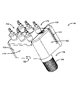
electrically coupled with the wire electrode to provide an electrical
connection between the
ignition module and an ignitor.
[0043] As an illustrative example, FIGURE 1A ¨ 1E are component diagrams
illustrating
various views of an example implementation of an ignition module 100. The
ignition module
comprises a top 102 and a bottom 104, a first end 106 and a second end 108,
and a first side 110
and a second side 112. Further, the ignition module 100 comprises a housing
114 and a battery
compartment 116. The housing 114 can house the electrical components that
convert stored
electrical power from a battery disposed in the battery compartment 116 into
electricity with
characteristics that are sufficient to provide a spark at a coupled ignitor.
[0044] Additionally, the housing 114 can comprise one or more grill
couplers 118 disposed
on the second side 112. The grill couplers can be configured to couple with
complementary
ignition module couplers disposed on a target grill. In some implementations,
the grill couplers
118 can be disposed on the top 102 of the housing 114. In some
implementations, the housing
can comprise one or more cover engagement couplers 120, illustrated as slots
in this example,
which are configured to couple with engagement couplers on a cover that can be
selectably
placed over the top 102 of the ignition module 100. The housing may also
comprise a cover
locking engagement member 122 that can be configured to selectably engage with
a
complementary member on the cover to selectably lock the cover on the top 102
of the ignition
module 100.
[0045] The battery compartment 116 can comprise the battery access portion
124, illustrated
in this example as a cap. In some implementations, the battery cap 124 can be
threadedly
engaged with the body 126 of the battery compartment, which is fixedly engaged
with the
housing 114, protruding from the bottom 104. That is, for example, the battery
compartment 116
can protrude vertically from the bottom 104 of the housing 114, such that the
when the housing
CA 03117101 2021-04-19
WO 2020/081921 PCT/US2019/056911
13
114 is engaged with the target grill, using the grill couplers 118, the
battery compartment 116 is
disposed downward vertically from the housing 114.
[0046] As illustrated, the example ignition module 100 can comprise one or
more ignitor
couplings 128. In some implantations, the ignitor couplings 128 can be
disposed on the top 102
of the ignition module 100, as illustrated, such as when the ignition module
100 engages with the
target grill from the second side 112. In alternate implementations, the
ignitor couplings 128 can
be disposed on one or more of the first side 110, second side 112, first end
106, or second end
108, and the grill couplers 118 can be disposed on the top 102 of the ignition
module 100, such
that the battery compartment 126 still remains disposed in a downward vertical
position.
[0047] Further, as illustrated, the housing can comprise ignition activator
connectors 130,
such as disposed on the top 102 of the ignition module 100. In alternate
implementations, the
ignition activator connectors 130 can be disposed on other sides of the
ignition module 100, such
as first side 110, second side 112, first end 106, or second, or even the
bottom 104. As an
example, the ignition activator connectors 130 can be configured to
electrically couple with an
ignition activator, such as a switch, button, or some other appropriate
electrical activator. For
example, the ignition activator can be activated (e.g., pressed), which
results in electrical power
from the battery being conditioned and fed to the ignitor coupling(s) 128,
leading to one or more
ignitors that provide an ignition source for fuel from the grill.
[0048] As an illustrative example, FIGURE 2 is a component diagram
illustrating an example
implementation of a plurality of ignitor couplings 128. In this example
implementation, the
ignitor coupling 128 can comprise a wiring connector 206. The wiring connector
can comprise a
wiring electrode shroud 202 and a wiring electrode coupler 204. Further, the
ignitor coupling
128 can comprise an ignitor connector 210, which comprises an ignitor
electrode shroud 208. As
an example, the wiring electrode coupler 204 can be fixedly engaged with an
ignitor wire (not
shown) that leads to an ignitor disposed in a target grill (not shown). In one
example, the wire
can be fixed to the wiring electrode coupler 204 by crimping the wire in the
wiring electrode
coupler 204, soldering (or otherwise gluing) the wire to the wiring electrode
coupler 204, using a
fastener, or some other appropriate connection, or a combination of these. As
an example, the
wiring electrode shroud 202 can surround the wiring electrode coupler 204, and
may provide a
guide for appropriate placement of the wiring electrode coupler 204 with
respect to the ignitor
CA 03117101 2021-04-19
WO 2020/081921 PCT/US2019/056911
14
electrode terminal for proper electrical engagement. Further, in some
implementations, the
wiring electrode coupler 204 can be covered in a water-resistant covering,
such as a plastic wrap,
shrink-wrap, or the like, to provide resistance to water intrusion into the
ignitor coupling 128.
100491 Further, the ignitor connector 210 may comprise an ignitor electrode
terminal
surrounded by the ignitor electrode shroud 208. As an example, the ignitor
electrode shroud 208
can be configured to selectably engage with the wiring electrode shroud 202,
such as by a
friction fit, and/or using a combination of ridges/shoulders to provide a
fixed coupling during
operation. In one implementation, in operation, the ignitor connector(s) 210
can protrude
upward from the top surface 102 of the housing 114, and can receive the wiring
connectors 206.
100501 With continued reference to FIGURES 1A-1E, and FIGURE 2, FIGURES 3A ¨
3C
are component diagrams illustrating an example implementation of an ignitor
coupling 128 as a
cutaway view, in section. As illustrated, the ignitor coupling 128 can
comprise the wiring
connector shroud 202 that is operably engaged with the ignitor electrode
shroud 208. In this
implementation, an inner surface of the wiring connector shroud 202 can
slidably engage with an
outer surface of the ignitor electrode shroud 208, as they can be configured
to fit together in
operation. Further, the inner surface of the wiring connector shroud 202 can
comprise a ridge or
shoulder 302 that is configured to selectably engage with a ridge or shoulder
304 on the outer
surface of the ignitor electrode shroud 208. In combination, the wiring shroud
ridge/shoulder
302 and the ignitor shroud ridge/shoulder 304 can operably form an ignitor
coupling locking
engagement 306.
100511 Additionally, the example ignitor coupling 128 can comprise the wire
electrode 308
that is electrically coupled with the wiring electrode coupler 204 (e.g.,
coupled with an ignitor
wire). In one implementation, the wire electrode 308 can be configured (e.g.,
shaped and sized)
to selectably engage with an ignitor electrode 310 that is electrically
coupled with the ignition
module 100, such as through an ignitor electrode coupler 312, the electrically
couples with
components in the ignition module 100. In one example, the ignitor electrode
310 can comprise
an electrically conductive post-shape that is configured to engage the wire
electrode 308 in
electrical coupling. In this example, the post can comprise a dome or cone
shape to help guide
the wiring electrode 308 into the electrical coupling. In this example, the
wiring electrode 308
can comprise a form (e.g., spring-like, u-shaped, v-shaped, or the like) that
is biased toward the
CA 03117101 2021-04-19
WO 2020/081921 PCT/US2019/056911
post, such that the wiring electrode 308 is forced against the post when
appropriately engaged
with the ignitor electrode 310. As illustrated, for example, the engagement of
the wiring
connector 206 with the ignitor connector 210 provide an electrical coupling
that is resistant to
water intrusion.
[0052] In one implementation the wiring connector 206 can comprise a
biasing component
314 that is used to bias the wiring electrode 308 away from the wall of the
wiring shroud 202,
and toward the ignitor electrode 310. The biasing component 314 can be
configured as a spring,
leaf, or any other appropriate shape, to reinforce the biasing action of the
wiring electrode 308
toward the ignitor electrode 310. In this way, for example, the electrical
coupling between the
wiring electrode 308 and the ignitor electrode 310 can be appropriately
maintained during
operation, and can provide for a longer life, less maintenance, and desired
performance of the
ignitor coupling 128.
[0053] In one aspect, a target grill may comprise an ignitor activator that
is used to activate
the ignition module to provide conditioned electricity to an ignitor disposed
in the grill. As one
example, the ignitor activator can comprise a button or electrical switch that
closes a circuit to
provide electricity to the ignitor, which provides a spark to ignite fuel in
the grill. As an
illustrative example, FIGURES 4A, 4B, 5A, and 5B are component diagrams that
illustrate one
example implementation of an ignitor activation module 400, that can be used
to initiate the
ignition module (e.g., 100 of FIGURE 1A) to activate an ignitor in the target
grill.
[0054] In this example implementation, the ignitor activation module 400
can take the form
of a type of button-shaped device that comprise a top 402 (e.g., or front,
depending on
disposition in the grill) a bottom 404 (e.g., or back), and a body 406. In
this implementation, the
top portion 402 can comprise a button-like user interface 408 that may be
pressed inward (e.g.,
downward or backward) by a user to activate the ignitor activation module 400,
and a top shroud
410 that surrounds the button-like user interface 408, for example, to provide
for weather-
resistance.
[0055] Further, the bottom portion 404 can comprise the body 406, module
connectors 412,
and appliance engagement coupler 414. The module connectors 412 can comprise
electrically
conductive materials that are configured to provide an electrical coupling
(e.g., close a circuit)
when the ignitor activation module 400 is activated, such as using the button-
like user interface
CA 03117101 2021-04-19
WO 2020/081921 PCT/US2019/056911
16
408. The module connectors 412 can be selectably engaged with an ignitor
module (e.g., 100),
for example, using ignition activator connections (e.g., 130 of FIGURE 1B). As
an example,
pressing the button 408 on the ignitor activation module 400 can close a
circuit between the
module connectors 412, which closed a circuit in the ignitor module (e.g.,
100) when the ignitor
activation module 400 is engaged with the ignition activator connections
(e.g., 130), thereby
generating an electrical pulse to an ignitor in the target grill.
[0056] Additionally, the ignitor activation module 400 can be engaged with
a target grill
using the grill engagement couplers 414. That is, for example, the grill
engagement couplers 414
may fit into slots disposed in a face of the grill, which forces the grill
engagement couplers 414
inward. In this example, the grill engagement couplers 414 are biased outward,
such that when
the grill engagement couplers 414 clear the face of the grill, the grill
engagement couplers 414
push back outward to provide a fixed engagement with the face of the grill. In
some
implementations, the ignitor activation module 400 can comprise an orientation
component 416,
such as a stop, shoulder, ridge, or the like, that aligns with a complementary
feature in the face of
the grill, such that the ignitor activation module 400 may merely properly
engage with the grill
when the orientation component 416 is properly aligned with the complementary
feature in the
face of the grill. In this way, for example, the ignitor activation module 400
may be placed in a
desired orientation in a grill for appropriate use by a user.
[0057] FIGURES 5A and 5B illustrate cut-away view, in perspective, of the
example, ignitor
activation module 400. With continued reference to FIGURES 4A and 4B, the
ignitor activation
module 400 can comprise a flexible member 502, having a body that is disposed
between, and
operably, fixedly engaged with, the button 408, acting a cover, and the shroud
410. As
illustrated, the body of the flexible member 502 can be configured to provide
resistance to
weather (e.g., wind, rain, snow, etc.) for the top portion 402 of the ignitor
activation module 400,
while allowing the button 408 to move appropriately between a static position
(e.g., not
activated, as illustrated) to an activated or depressed position (not shown).
The flexible member
can comprise a polymer, polymer blend, or some other appropriate material that
is both flexible
and weather resistant, for example, an may provide for a plurality of
movements back and forth
without damage.
CA 03117101 2021-04-19
WO 2020/081921 PCT/US2019/056911
17
[0058] As illustrated in FIGURES 5A and 5B, the button or activator 408 can
be disposed on
top of (e.g., or integrated with) the top surface of a plunger 504. The
plunger 504 can be
configured to act as a mechanical activation mechanism to facilitate opening
and closing of the
circuit, for example, to activate the ignitor activation module 400, as
described herein. The
bottom portion of the plunger 504 can be fixedly engaged with an activation
electrode 506 that
electrically couples (e.g., closes the circuit between) the respective module
connectors 412. As
illustrated, in this implementation, the tops 508 of the module connectors 412
are disposed inside
the body 406 of the ignitor activation module 400, and are not electrically
coupled in the static
position (e.g., button not depressed). However, the activation electrode 506
comprises standouts,
ears, or bends, which can contact the respective tops 508 of the module
connectors 506 to close
the circuit between them, and electrically couple them together, when the
plunger 504 is
depressed. In this way, pressing the button activator 408 can close the
circuit between the
module connectors 412.
[0059] Further, as illustrated, in this implementation, the ignitor
activation module 400 can
comprise a spring 512 disposed in the body 406. The bottom or backside of the
spring 512 can
be engaged with a spring shoulder 514 fixed inside the body 406; and the top
of the spring 512
can be engaged with the underside of the plunger 504 top. The spring can be
configured to bias
the plunger 504 outward/up, such that the activation electrode 506 is disposed
in an open circuit
position, as illustrated in FIGURES 5A and 5B. Additionally, the shroud 410
can be configured
to threadedly engage with body 406 in a threaded engagement 516. In this way,
for example, the
flexible member may be fixedly engaged with the body 406 and the shroud 410 to
improve the
weather resistance.
[0060] As an illustrative example, with reference to FIGURES 1-5, the
ignition module 100
may be engaged with a target grill (not shown), such as using the one or more
grill couplers 118.
Further, ignitor wires can be coupled to the ignition module 100 using the one
or more ignitor
couplers 128. Additionally, the ignitor activation module 400 can be coupled
to the ignition
module using the ignition activation connections 130, and coupled to the grill
using the grill
engagement couplers 414. In this example, a user may desire to ignite fuel at
a burner in the grill
using one or more ignitors disposed proximate the respective burners. As such,
the user can push
the button-like user interface 408, which closes the circuit in the ignitor
activation module 400,
closing the circuit between the battery in the battery compartment 1116 and
the ignitor
CA 03117101 2021-04-19
WO 2020/081921 PCT/US2019/056911
18
electrode310, thereby providing appropriate electrical power to one or more of
the ignitors,
which generate an ignition source (e.g., spark or plasma) proximate the burner
dispensing fuel,
igniting the fuel.
[0061] In another aspect, an improvement to the connection of wires with
the ignition module
may be devised, for example, to ease assembly of electrical connections to a
spark generator in a
gas appliance. In this aspect, for example, the electrical connections can
terminate in a polymer-
based block that comprises a connection point. The respective connection
blocks may be linked
together into a larger combined block. The combined block can be coupled with
a
complementary receiving block that is disposed on the spark generator. The
receiving block can
comprise spark generator connection points that electrically couple with the
corresponding
electrical connection point when the combined array is coupled to the
receiving block array.
[0062] In this aspect, the spark generator can have one or more connectors,
for example, for
connecting to an activator, such as a button or switch to activate the
generator, or connecting to
an ignitor wire or electrode that creates the spark. In one implementation,
the connection can be
achieved using modular connector components. In this implementation, the
modular connector
can comprise a plastic (e.g., some type of polymer-based material) block that
is fixedly engaged
with a metal connection point. For example, a first connection point may be
disposed on the
spark generator, fixedly engaged with a first plastic block; and a second
connection point may be
disposed on the end of a wire, fixedly engaged with a second plastic block. In
this example, the
first plastic block can be selectively, releasably engaged with the second
plastic block. Further,
in this example, connecting the first plastic block with the second plastic
block electrically
couples the first connection point with the second connection point. In this
way, for example,
connecting the first plastic block with the second plastic block creates an
electrical coupling
between the wire and the spark generator.
[0063] In one implementation of a system for improving ease of assembly of
electrical
couplings in a gas appliance can comprise a first engaging block that
comprises a polymer-based
material formed into a block. The first engaging block can comprise a first
electrical component
connection point at a terminus of a first electrical coupling. Further, a
second engaging block can
comprise a polymer-based material formed into a block. The second engaging
block can
comprise a second electrical component connection point at a terminus of a
second electrical
CA 03117101 2021-04-19
WO 2020/081921 PCT/US2019/056911
19
coupling. The second engaging block can couple with the first engagement block
in a selectively
fixed arrangement resulting in a combined block. Additionally, a receiving
block array can be
disposed on a spark generator of a gas appliance. The receiving block array
can comprise a
polymer-based material formed into a block that receives and selectively,
fixedly couples with
the combined block. The receiving block array can comprise a first spark
generator connection
point and a second spark generator connection point respectively electrically
coupled with the
spark generator. The first electrical coupling and the second electrical
coupling can respectively
electrically couple with the first spark generator connection point and a
second spark generator
connection point when the receiving block is fixedly coupled with the combined
block.
[0064] In this aspect, in one implementation, the plastic connection blocks
can be used to
make assembling electrodes (e.g., high voltage (HV) connections) and other
connections on a
grill or appliance easier, using less force, and resulting in an improved
coupling. For example, in
this implementation, the insertion force can be reduced by coupling two or
more of the modular
connector blocks together to form a larger, single connector containing the
respective
connections for a particular system coupled with the generator. In this
example, this larger,
assembled connector, can be easily coupled with (e.g., snapped on to) the
spark generator in one
motion, instead of several connections.
[0065] Additionally, in one implementation, the plastic blocks can be
configured to hold the
connection together. That is, for example, the first plastic block may be
configured to couple
with the second plastic block such that they (e.g., selectively, releasably)
lock together. In this
way, the force used to couple the connections can be reduced, and the number
of connection
motions of the iterative process of coupling the connections can be reduced.
In this aspect, the
benefit of the modular connection includes a reduction in the insertion force
used to couple the
connections, which can increase productivity. Further, the reduced insertion
force of connector
can improve safety of an assembly line worker who, typically, has to connect
sometimes
thousands of these connectors every shift.
[0066] In one implementation, the connectors can be color-coded, for
example, such
connectors that couple together (e.g., the first block and the second block)
comprise
corresponding colors (e.g., the same color). In this way, for example, an
installer (e.g., factory
worker, end user, repair person) can easily recognize the appropriate
connections. That is, for
CA 03117101 2021-04-19
WO 2020/081921 PCT/US2019/056911
example, an array of connection points can be disposed on a spark generator
respectively
corresponding to an electrical connection (e.g., one or more activators, such
as for individual
burner, one or more electrodes to generate a spark, one or more power supply
inputs). In this
example, respective connection points can be engaged with (e.g., disposed in)
a plastic block that
is color coded with a different color (e.g., for each type of different
connection used). Further,
respective electrical couplings (e.g., wires) can have a connection point
engaged with (e.g.,
disposed in) a plastic block that comprises a color corresponding to one of
the color coded blocks
on the spark generator. In this example, a user may simply connect (e.g.,
slide, snap, rotate, fit,
or otherwise engage) the blocks for respective couplings together into a
larger, combined block
of connected individual unit blocks in an arrangement corresponding to the
color-coded
arrangement on the spark generator. The user can engage (e.g., slide, snap,
rotate, fit, or
otherwise engage) the combined block with the array of color coded blocks on
the spark
generator with one motion. In this way, the user can, more easily electrically
connect the various
parts of a system with the spark generator in a manner that is more efficient,
with less effort, and
in a correct alignment.
[0067] In one implementation, a poka-yoke concept can be incorporated into
the design of the
blocks. For example, the poka-yoke design means that the connectors cannot be
assembled
incorrectly. That is, for example, respective blocks in an array of blocks
that are coupled
together, are configured in a way that allows them to only fit in one
arrangement. In this way,
the respective electrical connections can only be made in one arrangement,
which mitigates the
chances of improper installation. As one example, the first block may be
configured to only fit
in electrical engagement with the second block in one way, such that the shape
and/or size of the
respective blocks allows for the coupling to take place in only one manner.
Further, a third block
(e.g., on a park generator connection point) may be configured to merely fit
in electrical
engagement with a fourth block (e.g., on a wire connection point) in one way.
In one
implementation, the second block and the fourth block may be configured to
couple together in
merely one arrangement to form the larger combined block array, to couple with
the first and
third blocks. In this way, for example, the appropriate electrodes can be
attached to the
appropriate terminals on the spark generator.
[0068] In one implementation, the color-coded arrangement of the connectors
can be
combined with the poka-yoke design of the connectors. In this way, the ease of
assembly of the
CA 03117101 2021-04-19
WO 2020/081921 PCT/US2019/056911
21
larger combined blocks can be improved with a visual confirmation of the
appropriate
arrangement. Further, assembly is improved for all of the users, such as the
factory worker who
is assembling the product that is sent to consumers, the end user who may be
repairing or
assembling the grill, and the repair person who performs maintenance and
repair.
100691 As illustrated in FIGURES 1A-1E, and 2, an ignition module 100, such
as a spark
generator, can comprise with existing electrical coupling points (e.g., 128).
In this example, the
spark generator has a plurality of separate, individual electrode connection
points disposed on the
outer case, respectively comprising a metal connection point, configured as a
male connector
(e.g., a metal wire sticking out of the colored shrouds). Further, respective
coupling wires have a
small, female connection point disposed at the end. The female connection
point is merely a
hollow metal tube that slides onto the male connection point with a friction
fit. The force needed
to slide the female connection point onto the male connection point is
significant, as the friction
fit need to be sufficient to hold them in electrical coupling during assembly
and use. For
example, the force needed to couple the connection points, along with the
overall design, often
leads to damage to the electrical coupling, such by bending and/or cracking
the wire, connection
point, or the engagement between the connection point and the wire or spark
generator.
100701 FIGURE 6 is a component diagram illustrating one implementation of a
system 600
for improving the ease of installation of connections between the spark
generator 602 and the
various components of a gas-fired appliance. In this example, system 600, the
spark generator
602 can comprise a receiving block array 604. The receiving block array 604
may comprise a
single unit configured to couple (e.g., receive) with one or more engaging
blocks 608; or the
block array 604 may comprise a combination of two or more units configured to
respectively
couple with one or more engaging blocks 608. In this implementation, the
receiving block array
604 can comprise one or more spark generator connection points 606, disposed
in the block array
604. The spark generator connection points 606 can be disposed in electrical
coupling with
corresponding components in the spark generator 602.
100711 In FIGURE 6, the example system 600 can comprise the one or more
engaging blocks
608. The respective engaging blocks 608 can be engaged with an electrical
coupling (e.g., wire)
that telminates at a coupling connection point 612 disposed in the
corresponding engaging block
608. In this example, two or more engaging blocks 608 can be coupled together
in a selectively
CA 03117101 2021-04-19
WO 2020/081921 PCT/US2019/056911
22
fixed arrangement, and the resulting larger combined engaging block array 614
can be coupled
with the receiving block array 604, such as with one motion. In one
implementation, the
receiving block array 604 and the combined block array 614 can be configured
to couple
together in a selectively fixed arrangement, such that they may not uncouple
during typical use.
That is, for example, a locking mechanism may be disposed on (e.g., formed
with) the respective
block arrays; and the locking mechanism may couple together in a complementary
arrangement
when engaged appropriately.
[0072] The word "exemplary" is used herein to mean serving as an example,
instance or
illustration. Any aspect or design described herein as "exemplary" is not
necessarily to be
construed as advantageous over other aspects or designs. Rather, use of the
word exemplary is
intended to present concepts in a concrete fashion. As used in this
application, the term "or" is
intended to mean an inclusive "or" rather than an exclusive "or." That is,
unless specified
otherwise, or clear from context, "X employs A or B" is intended to mean any
of the natural
inclusive permutations. That is, if X employs A; X employs B; or X employs
both A and B, then
"X employs A or B" is satisfied under any of the foregoing instances. Further,
at least one of A
and B and/or the like generally means A or B or both A and B. In addition, the
articles "a" and
"an" as used in this application and the appended claims may generally be
construed to mean
"one or more" unless specified otherwise or clear from context to be directed
to a singular form.
[0073] Although the subject matter has been described in language specific
to structural
features and/or methodological acts, it is to be understood that the subject
matter defined in the
appended claims is not necessarily limited to the specific features or acts
described above.
Rather, the specific features and acts described above are disclosed as
example forms of
implementing the claims. Reference throughout this specification to "one
implementation" or
"an implementation" means that a particular feature, structure, or
characteristic described in
connection with the implementation is included in at least one implementation.
Thus, the
appearances of the phrases "in one implementation" or "in an implementation"
in various places
throughout this specification are not necessarily all referring to the same
implementation.
Furthermore, the particular features, structures, or characteristics may be
combined in any
suitable manner in one or more implementations. Of course, those skilled in
the art will
recognize many modifications may be made to this configuration without
departing from the
scope or spirit of the claimed subject matter.
CA 03117101 2021-04-19
WO 2020/081921 PCT/US2019/056911
23
100741 Also, although the disclosure has been shown and described with
respect to one or
more implementations, equivalent alterations and modifications will occur to
others skilled in the
art based upon a reading and understanding of this specification and the
annexed drawings. The
disclosure includes all such modifications and alterations and is limited only
by the scope of the
following claims. In particular regard to the various functions performed by
the above described
components (e.g., elements, resources, etc.), the terms used to describe such
components are
intended to correspond, unless otherwise indicated, to any component which
performs the
specified function of the described component (e.g., that is functionally
equivalent), even though
not structurally equivalent to the disclosed structure which performs the
function in the herein
illustrated exemplary implementations of the disclosure.
100751 In addition, while a particular feature of the disclosure may have
been disclosed with
respect to only one of several implementations, such feature may be combined
with one or more
other features of the other implementations as may be desired and advantageous
for any given or
particular application. Furthermore, to the extent that the terms "includes,"
"having," "has,"
"with," or variants thereof are used in either the detailed description or the
claims, such terms are
intended to be inclusive in a manner similar to the term "comprising."