Note: Descriptions are shown in the official language in which they were submitted.
DESCRIPTION
of the patent for an Industrial Invention having the title:
"LEVELLING SPACER DEVICE"
on behalf of RAIMONDI S.P.A. with registered offices in 41122 MODENA (MO).
* * * * *
TECHNICAL FIELD
The present invention relates to a levelling spacer device for the laying of
slab-
type manufactured products, such as tiles, slabs of natural stone or the like,
for
coating surfaces, such as walkable surfaces, floors, wall and ceiling
coverings or
.. the like.
PRIOR ART
In the sector of tile laying for coating surfaces, such as floors, walls and
the like,
the use of spacer devices is known which, in addition to equally spacing the
tiles
placed side by side, allow their planar arrangement, such devices are commonly
called levelling spacer devices.
The levelling spacer devices of the known type generally comprise a base,
which
can be positioned below the laying surface of at least two adjacent tiles,
from
which at least a spacer bridge protrudes, adapted to contact, by means of its
lat-
eral sidewalls, the facing sidewalls of the two tiles to be placed side by
side on
the laying surface.
The levelling spacer device is then provided with a pressure wedge adapted to
wedge between a crosspiece of the spacer bridge and the surface, in view, of
the
tiles resting on the base, so as to press the visible surfaces of the tiles
towards
the base, levelling them.
The bridge is then removed by separation from the base following the
solidifica-
2
Date Recue/Date Received 2021-05-11
tion of the tile laying adhesive, leaving, for single-use, the base underneath
the
tile laying surface incorporated in the solidified adhesive.
A need felt in these levelling spacer devices, especially in those having
bridges in
which the legs that determine the thickness of the joint between the tiles
have a
reduced thickness, for example of about 1 mm or less, and which therefore
allow
to significantly reduce the distance between two adjacent tiles, is the fact
that this
bridge is not ripped off at the time of insertion of the pressure wedge, i.e.
that the
bridge has a high tensile strength, allowing, at the same time, to decrease
the re-
sistance to bending or shearing, i.e. to allow an effective and comfortable
removal
of the bridge following the solidification of the adhesive for the laying of
the tiles.
In general, a need felt in these levelling spacer devices is to make the
separation
of the bridge from the base more and more effective and simple once the adhe-
sive has hardened while maintaining, however, a good tensile strength of the
bridge itself that is useful for effectively exercising, by means of the
pressure
wedge, a pressure on the tiles to be levelled.
Furthermore, a need felt in such levelling spacer devices is to guide the
fracture
of the bridge from the base as much as possible along pre-established and non-
random cutting lines, limiting as much as possible that the separation line
runs
along random and uncontrolled paths, and - therefore - to avoid that unremoved
portions of the legs of the bridge remain trapped in the joint lines between
the
tiles.
An object of the present invention is to meet the aforementioned need of the
prior
art, within the context of a simple and rational solution and at a contained
cost.
Such objects are achieved by the characteristics of the invention given in the
in-
dependent claim. The dependent claims outline preferred and/or particularly ad-
3
Date Recue/Date Received 2021-05-11
vantageous aspects of the invention.
DISCLOSURE OF THE INVENTION
The invention, in particular, provides a levelling spacer device for the
laying of
slab-shaped products for coating surfaces, comprising:
- at least one base having a lower surface and an opposite upper surface
defining a support plane for two slab-shaped products placed side by side;
- a spacer bridge perimetrically delimiting a through opening adapted to be
crossed by a pressure wedge along a crossing direction, wherein the bridge is
provided with:
- at least two legs placed side by side between each other along a flanking
direction orthogonal to the crossing direction and each one projecting from a
re-
spective portion of the upper surface of the base, in a direction orthogonal
there-
to, wherein each leg of the bridge is frangibly connected to the respective
base
portion; and
- a crosspiece, which joins the top of the two legs along the flanking
direc-
tion;
wherein each leg has:
- an inner sidewall provided with a top end which joins at the crosspiece
and
a base end which joins at the upper surface of the base, wherein the inner
side-
.. wall delimits laterally the through opening; and
- an opposite outer sidewall, wherein the outer sidewall is provided with a
top end which joins at the crosspiece and a base end which joins at the base,
wherein the top end of the outer sidewall is placed at a first distance along
the
flanking direction from the top end of the inner sidewall and the base end of
the
outer sidewall is placed at a second distance along the flanking direction
from the
4
Date Recue/Date Received 2021-05-11
base end of the inner sidewall,
wherein at least one of the outer sidewall and the inner sidewall (preferably
the
outer sidewall) of each leg converges towards the other of the inner sidewall
and
the outer sidewall (preferably the inner sidewall) of the same leg, so that a
ratio
between the second distance and the first distance is lower than 1.
In other words, the outer sidewall and inner sidewall of each leg converge
(toward
each other), so that a ratio between the second distance and the first
distance is
lower than 1.
Thanks to this solution, it is possible to address and localize the fracture
of each
leg in the desired point, allowing, at the same time, a high mechanical
strength of
the bridge during use and also at the time when it is acted thereon with an
impul-
sive force (a kick or a blow of a hammer or similar) suitable for triggering
the frac-
ture thereof.
Moreover, thanks to this solution, a good compromise is reached between the
high tensile strength of each leg, i.e. its function as a traction element of
the base
under the thrust effect of the pressure wedge, and the good shear and/or
flexural
breakability of each leg itself, which allows the effective removal of the
bridge
once the tiles are firmly in place, so as to minimize the amount of residual
materi-
al remaining in the interspace (or joint) between the laid tiles.
In practice, it has been observed that, thanks to such a solution, the impact
zone
of the device (i.e., the crosspiece or the zone proximal to the top end of the
outer
sidewall of each leg) is reinforced and, at the same time, the impulsive
stress is
effectively transmitted to the zone assigned to the fracture of the leg from
the
base, i.e., to the zone proximal to the base end of the outer and inner
sidewalls of
the legs, with the result that the fracture is driven exactly at the desired
point and
5
Date Recue/Date Received 2021-05-11
does not propagate randomly in the leg.
The above advantages and results are also achieved when the legs of the bridge
have reduced thicknesses (i.e. when the device is used to define very small
joints
between very reduced tiles) for example less than or equal to 1 mm.
BRIEF DESCRIPTION OF THE DRAWINGS
Further characteristics and advantages of the invention will become clear from
reading the following description provided by way of non-limiting example,
with
the aid of the figures illustrated in the accompanying tables.
Figure 1 is an axonometric view of an embodiment of a levelling spacer device
according to the invention.
Figure 2 is a front view of Figure 1.
Figure 3 is a side view of Figure 1.
Figure 4 is a plan view from above of Figure 1.
Figure 5 is a sectional view along the trace of section v-v of Figure 6.
Figure 6 is an enlargement of detail vi of Figure 2.
Figure 7 is a sectional view along the trace of section v11-\/11 of Figure 6.
Figure 8 is an axonometric view of a pressure wedge of a levelling spacer
device,
according to the invention.
Figure 9 is a side view of a levelling spacer device in operating
configuration.
Figure 10a is a schematic plan view of a first possible tile laying scheme, so-
called "straight".
Figure 10b is a schematic plan view of a second possible tile laying scheme,
so-
called "staggered".
Figure 10c is a schematic plan view of a third possible tile laying scheme, so-
called "complex".
6
Date Recue/Date Received 2021-05-11
BEST MODE OF THE INVENTION
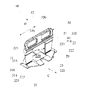
With particular reference to these figures, the reference number 10 gener-
ally designates a levelling spacer device adapted to facilitate the laying
slab-type
manufactured products, such as tiles and the like, generally indicated with
the let-
ter P, and adapted for coating surfaces, i.e. flooring, walls, ceilings and
the like.
The device 10 comprises a base 20, which is, for example, slab-shaped
with an enlarged shape, for example polygonal.
The base 20, in the example shown, is a monolithic body which has an irregular
(plan) shape, for example substantially octagonal.
The base 20 comprises a lower surface 21, for example substantially flat or
shaped or or other shape.
The lower surface 21 is intended to be placed against (or otherwise come into
contact with) a layer of adhesive disposed on the screed that is intended to
be
covered by the tiles P.
The base 20 also comprises an upper surface indicated as a whole with number
22.
The upper surface 22 can be substantially flat or variously shaped according
to
the needs.
In the illustrated examples, the upper surface 22 comprises a raised first
portion
220 (central in the example) defining a support plane for two tiles P placed
side
by side.
The support plane, i.e., the highest surface portion of the upper surface 22
defin-
ing the first portion 220 (or in other words, the surface portion of the upper
sur-
face 22 furthest away from the lower surface 21, i.e., its lowest apical
portion
where provided) is located at a first distance dl from the lower surface 21.
7
Date Recue/Date Received 2021-05-11
The support plane (i.e. the first portion 220 of the upper surface 22) is the
surface
of the base 20 furthest away from the lower surface 21.
In practice, the maximum thickness of the base 20 is defined by the first
distance
dl.
The support plane is substantially parallel to the lower (planar) surface 21.
The upper surface 22 of the base 20 furthermore comprises two second portions
222 (lateral in the example) mutually opposite with respect to the first
(central)
portion 220, for example symmetrical (and equal) with respect to a median
plane
M of the base 20 orthogonal to the support plane and intersecting the first
portion
220 and the second portions 222.
Each second portion 222 defines a planar surface placed at a second distance
d2
from the lower surface 21, wherein for example the second distance d2 is less
than the first distance dl.
In practice, the thickness of each second portion 222 of the base 20 is
defined by
.. the second distance d2 and is less than the thickness of the first portion
220 of
the base (wherein the thickness of the first portion 220 is the minimum
thickness
of the base 20).
It is not excluded, however, that at worst the second distance d2 may be equal
to
the first distance dl.
Alternatively, it is also possible to provide that the second distance d2 may
be
greater than the first distance dl, in which case the support plane for the
tiles P
would be defined by the second portion 222.
Each second portion 222 is, for example, planar and defines a plane
substantially
parallel to the lower surface 21 (planar) and the support plane (distinct
there-
from).
8
Date Recue/Date Received 2021-05-11
The upper surface 22 comprises a connecting surface interposed between each
planar surface and the support plane.
The connecting surface is substantially orthogonal to the planar surface and
to
the support plane, defining the elevation of a step between them.
Each second portion 222 of the upper surface 22, i.e. each planar surface, has
a
longitudinal development, i.e. has a prevalent development direction, along a
lon-
gitudinal axis A, which is orthogonal to the median plane M of the base 20
which
intersects the first portion 220 and the second portions 222.
In practice, each planar surface defines an elongated strip (having a length
greater than the width) with longitudinal axis orthogonal to the aforesaid
median
plane M of the base 20 and placed at a lower level than the level defined by
the
support plane defined by the first portion 220 of the base 20.
The planar surface has a substantially trapezoidal plan shape, for example of
an
isosceles trapezoid, wherein the larger base is near the support plane, i.e.
is
joined thereto by means of the connecting surface, and the smaller base, oppo-
site it, defines the lateral (free) end distal from the first portion 220 of
the base 20.
The base 20, in the illustrated example, also comprises a reinforcing element
23,
for example configured to strengthen the base 20 (with respect to the
torsional or
flexural stresses to which it is subjected during operation) and/or to widen
the
support plane defined by the first portion 220 and/or to widen the lower
surface
21.
In the example, the base 20 comprises two reinforcing elements 223, for exam-
ple, placed on opposite sides from the first portion 220. Each reinforcing
element
223 is defined by a longitudinal beam, for example with circular cross-section
(although it is not excluded that it may have a polygonal cross-section, for
exam-
9
Date Recue/Date Received 2021-05-11
pie rectangular), the longitudinal axis of which is orthogonal to the median
plane
M.
The reinforcing element 223 has a thickness that (at most) is equal to the
maxi-
mum thickness of the base 20 (i.e., equal to the first distance dl of the
upper por-
tion 220 from the lower surface 21).
In practice, each reinforcing member 223 defines a base wall (or directrix)
sub-
stantially coplanar to the lower surface 21 and an opposite top wall (or
directrix),
which preferably is substantially coplanar to the first portion 220 of the
upper sur-
face 22.
The axial ends of each reinforcing element 223 are tapered, for example so as
to
define, each, a ramp degrading towards the outer periphery (i.e. the
reinforcing
elements have gradually decreasing thickness from a maximum thickness - cen-
tral - to a minimum thickness - at the axial end -).
In practice, the top wall (or directrix) of each reinforcing element 223
defines an
enlarged portion of the support plane, i.e., defines a rest for the tiles P
(together
with the first portion 220). For example, each second portion 222 is
interposed
(along a flanking direction parallel to the median plane M and the support
plane
defined by the first portion 220) between the first central portion 220 and (a
top
wall or directrix of) a respective reinforcing element 223.
In practice, each reinforcing element 223 is fixed to the smaller base of (the
isos-
celes trapezoid defined by) the second portion 222.
It is not excluded that the reinforcing element 223 in an alternative variant
may
have a thickness greater than the maximum thickness of the base 20 (i.e. equal
to the first distance dl of the upper portion 220 from the lower surface 21),
in
which case the support plane for the tiles P may be defined (exclusively) by
the
Date Recue/Date Received 2021-05-11
reinforcing elements 223.
In the example, the length of the reinforcing element 223 is (slightly)
greater than
the length of the aforesaid smaller base.
The upper surface 22 of the base 20 comprises a pair of tilted surfaces 225 op-
posite with respect to the median plane M of the base 20 which intersects the
first
portion 220 and the second portions 222.
Each tilted surface 225 defines a ramp projecting from the end of the base 20
to-
wards the aforesaid median plane M in a direction orthogonal to the median
plane
M and connecting the lower surface 21 of the base 20 to the support plane of
the
first portion 220 and/or defined by (the top walls or directrices of) the base
20.
Each tilted surface 225 has a maximum distance from the lower surface 21 equal
to the first distance dl and a minimum distance from the lower surface 21 com-
prised between zero and the second distance d2, preferably equal to the second
distance d2.
Each tilted surface 225 lies on a tilted plane of an acute (internal) angle
with re-
spect to the lower surface 21.
In practice, each tilted surface 225 has a central portion connecting the
first por-
tion 220 to the lower surface 21 and two lateral portions each connecting the
top
wall or directrix of a respective reinforcing element 223 to the lower surface
21
(i.e., the base wall or directrix) thereof.
The base 20 comprises a pair of opposite slots 23 passing from the lower
surface
21 to the upper surface 22, which are located at the first portion 220 of the
upper
surface 22.
Each slot 23 has an elongated shape, i.e. it has a prevalent development direc-
tion, along a longitudinal axis orthogonal to the median plane M of the base
20
11
Date Recue/Date Received 2021-05-11
which intersects the first portion 220 and the second portions 222.
In practice, each slot 23 has a longitudinal axis parallel to the longitudinal
axis of
the second portions 222 of the upper surface 22 of the base 20.
Each slot 23 is open laterally at a respective end of the base 20 distal from
the
median plane M.
Each slot 23 defines a longitudinal through slit of the base 20 from the end
that is
distal from the median plane M towards it and with a prevalent direction
orthogo-
nal thereto.
The length of each slot 23 is substantially equal to one-half of the length of
the
base 20 in the direction orthogonal to the median plane M, e.g., it is
comprised
between 0.4 times and 0.55 times the one-half of the length of the base 20 in
the
direction orthogonal to the median plane M.
For example, each slot 23 is adapted to intersect a respective tilted surface
225
(i.e., the central portion thereof) by dividing it into two separate portions
along a
direction parallel to the median plane M and to the lower surface 21.
The base 20, in particular the upper surface 22 thereof (except for the tilted
sur-
faces 225), has a surface roughness substantially comprised between 20VDI -
30VD1.
The device 10 comprises a spacer bridge 30 which, in use, is adapted to
.. contact at least one portion of the facing sidewalls of the at least two
tiles P rest-
ing on the support plane of the upper surface 22 of the base 20.
The bridge 30 comprises two (identical) legs 31 projecting from the base 20,
for
example, each leg is projecting from a respective second portion 222 of the
upper
surface 22 of the base 20 in an orthogonal direction with respect to at least
the
first portion 220 of the upper surface 22 of the base itself.
12
Date Recue/Date Received 2021-05-11
In practice, each leg 31 has a basal end with which it is connected to the
base 20.
The legs 31 are placed side by side along a parallel (and lying) flanking
direction
Don the median plane M of the base 20 and mutually spaced apart.
The bridge 30 then comprises a crosspiece 32 which joins the top of the two
legs
31 and is arranged with a longitudinal axis parallel to the flanking direction
D and
parallel and at a distance from the upper surface 22 of the base 20.
The bridge 30 is for example made as a single body with the base 20, for exam-
ple by injection molding of plastic material.
For example, the bridge 30 (as well as the base 20) is made of (or consists
of) a
polymeric material comprising (preferably, consisting of) polypropylene (PP)
or
polyethylene (PE), for example free of polyamides (Nylon).
For example, the polymeric material comprises a mixture of a first
polypropylene,
so-called structural, (60%) and of a second polypropylene, so-called
elasticizing,
(40%), wherein the second polypropylene has a greater elasticity than the
elastic-
ity of the first polypropylene.
The bridge 30 is defined globally by a slab-shaped body arranged parallel to
the
median plane M of the base 20, so that the median plane M of the base 20 is
also
a median plane of the bridge 30 itself.
Each leg 31 of the bridge 30 has a lower end fixed to (i.e., derived from) the
base
20, or the upper surface 22 thereof, in particular is fixed to (i.e., derived
from) the
planar surface of the respective second portion 222.
Each leg 31 of the bridge 30 is substantially slab-shaped, i.e., it has a
thickness
(wherein thickness means the dimension developing in the direction orthogonal
to
the median plane M) defining the minimum dimension of the leg 31.
The reinforcing elements 223 are placed on opposite sides with respect to the
13
Date Recue/Date Received 2021-05-11
bridge 30 with respect to the flanking direction D, i.e., they are placed
outside the
legs 31 of the bridge 30 with respect to the flanking direction D (i.e., they
define
the free ends of the base 20 along said flanking direction D).
Each leg 31, for example, is interposed (along the flanking direction D
between a
reinforcing element 223 and the central portion 220.
In addition, the two reinforcing elements 223 (sleeves) are placed on opposite
sides with respect to the first portion 220 and each second portion 222 is
inter-
posed (along the flanking direction D of the legs 31) between the first
central por-
tion 220 and a respective reinforcing element 223.
Furthermore, each leg 31 has a height (wherein height means the dimension de-
veloping in a direction parallel to the median plane M and orthogonal to the
sup-
port plane defined by the base 20) defining the maximum dimension of the leg
31.
In practice, each leg 31 has a longitudinal axis (prevalent direction)
orthogonal to
the first portion 220 (or even to the planar surface of the second portion 222
from
which it derives).
Each leg 31 has a height greater than the thickness of the tiles P to be
placed
side by side, so that the crosspiece 32 of the bridge 30 is always at a level
(dis-
tance from the lower surface 21) greater than the level of the surface, in
view, of
the tiles P to be placed side by side.
Each leg 31 has a thickness that may be constant over the entire height of the
leg
31 or, as in the example, variable (e.g., in sections) along the longitudinal
axis
thereof.
For example, each leg 31 comprises a central sector 311 axially interposed be-
tween the top of the leg (i.e., the portion of the leg that joins the
crosspiece 32)
and the basal end of the leg 31, wherein the central sector 311 is provided
with
14
Date Recue/Date Received 2021-05-11
two main faces opposite to the median plane M and parallel to each other.
The main faces of the central sector 311 are the zone of the leg 31 which
comes
into contact with the side-by-side tiles P resting on the first portion 220 of
the up-
per surface 22 of the base 20 defining their mutual distance in a direction
orthog-
onal to the median plane M.
The distance between the main faces (i.e., the thickness of the central sector
311) defines the width of the joint (interspace) between the tiles P.
For example, the thickness of each leg 31 at each main face is suitably
calibrat-
ed, for example it is equal to 1 mm, 0.5 mm or multiples.
In practice, the height of the central sector 311 is at least equal greater
than the
thickness of the tiles P to be placed side by side, so that the crosspiece 32
of the
bridge 30 is always at a level (distance from the lower surface 21) greater
than
the level of the surface, in view, of the tiles P to be placed side by side.
Furthermore, the height of the central sector 311 represents the prevalent
height
of the height of the entire leg 31.
In the case where the thickness of the leg 31 is constant along the entire
longitu-
dinal development thereof, then the leg 31 consists entirely of the aforesaid
cen-
tral sector 311.
Each leg 31, further, may (alternatively) comprise a top connecting sector
312,
which is configured to join the leg 31 (i.e., the top of the central sector
311) to the
crosspiece 32.
For example, the top connecting sector 312 has a greater thickness (overall)
than
the thickness of the central sector 311, e.g. increasing (steadily) from its
lower
end (joined to the upper end of the central sector) to its upper end defining
the
top end of the leg 31 itself (and joining the crosspiece 32).
Date Recue/Date Received 2021-05-11
Each leg 31 then comprises a basal connecting block 313 configured to intercon-
nect/join the leg 31 (i.e., the lower end of the central sector 311) to the
(upper
surface 22 of the) base 20, i.e., the respective second portion 222.
The block 313 may have, as will be better described below, a thickness
(globally)
lower than (or at most equal to) the mutual distance between the two sidewalls
of
the central sector 311.
The block 313 has an upper end connected to the central sector 311 and a lower
end, coinciding with the basal end of the leg 31 as a whole, directly
connected to
the (upper surface 222 of the) base 20 (i.e. to the respective second portion
222)
and an upper end joined to the lower end of the central sector 311.
Each leg 31, then, has a width (wherein width means the dimension developing
in
a direction parallel to the median plane M and parallel to the support plane
de-
fined by the base 20, i.e. parallel to the flanking direction D) defining a
dimension,
for example, comprised between the height and the thickness of the leg 31.
Preferably, each leg 31 has a variable width along the height of the leg 31,
i.e.,
along the longitudinal development thereof.
For example, each leg 31 has a pair of opposite sidewalls that laterally
delimit the
leg 31.
More in detail, each leg 31 comprises an inner sidewall 314 provided with a
top
end (at the top end of the leg 31 and concurring to define the same) that
joins (di-
rectly) to the crosspiece 32 and an opposite base end (at the basal end of the
leg
31 and concurring to define the same) that joins to (the upper surface 22 of)
the
base 20 (i.e. the respective second portion 222 thereof).
The inner sidewall 314 of each leg 31 faces the inner sidewall 314 of the
other leg
31 and is placed at a predetermined (non-zero) distance DO therefrom, for exam-
16
Date Recue/Date Received 2021-05-11
pie equal to or greater than the width of the first portion 220 (in the
flanking direc-
tion D of the legs 31).
For example, the inner sidewall 314 of each leg 31 is planar and lies in a
plane
orthogonal to the median plane M and the support plane (defined by the base
20,
i.e., orthogonal to the first portion 220 of the upper surface 22)
In practice, the inner (planar) sidewall 314 delimits the central sector 311
and
(where provided) the top connecting sector 312 and the block 313) of the leg
31
(squared with the main faces of the central sector 311).
Each leg 31, moreover, comprises an opposite outer sidewall 315, which is pro-
vided with a top end (at the top end of the leg 31 and concurring to define
the
same) that joins (directly) to the crosspiece 32 and an opposite base end (at
the
basal end of the leg 31 and concurring to define the same) that joins to (the
upper
surface 22 of) the base 20 (i.e. of the respective second portion 222
thereof).
The top end of the outer sidewall 315 is placed at a first distance W1 from
the top
end of the inner sidewall 314 along the flanking direction D.
Further, the base end of the outer sidewall 315 is placed at a second distance
W2
from the base end of the inner sidewall 314 along the flanking direction D.
In particular, the second distance W2 is lower than the first distance W1,
i.e., the
ratio between the second distance W2 and the first distance W1 is lower than
1:1.
Preferably, the aforesaid ratio is comprised between 0.95:1 and 0.5:1, more
pref-
erably between 0.9:1 and 0.8:1 e.g. equal to 0.84+/-1:1.
For example, the second distance W2 is substantially equal to (or slightly
lower
than) half the distance DO between the inner sidewalls 314 of the two legs 31.
For example, the second distance W2 is lower than the width of the planar sur-
face of the respective second portion 222 (from which it derives), in practice
a
17
Date Recue/Date Received 2021-05-11
(hollow) gap is defined between the basal end of each leg 31 and the
connecting
surface (joining the first portion 220 and the second portion 222) and/or the
rein-
forcing element 223.
The second distance W2 is the minimum distance between the inner sidewall 314
and the outer sidewall 315 of the respective leg 31, i.e. it defines the
minimum
width of the (entire) leg 31.
Particularly, the outer sidewall 314 and the inner sidewall 314 converge with
each
other so that the width of the leg 31 decreases from the top end towards the
ba-
sal end of the leg, i.e., so that the basal end of the leg 31 has a width
lower than
the top end of the leg 31 (or, in other words, so that the basal end of the
leg 31 is
tapered along the flanking direction D with respect to the top end of the
leg).
In more detail, the (only) outer sidewall 315 converges towards the inner
sidewall
314.
The outer sidewall 315 (or at least a portion thereof, as will be described
below)
lies on a tilted plane which intersects the lying plane of the inner sidewall
314 on
an imaginary intersecting line, which is orthogonal to the median plane M and
lies
below the upper surface 22 of the base 20, preferably on the opposite side of
the
leg 31 with respect to the base 20 (i.e. inferiorly to the lower surface 21 of
the
base 20).
The outer sidewall 315 of each leg comprises (or consists of) a (single)
tilted sec-
tion 3150, converging towards the inner sidewall.
The tilted section 3150, in essence, is planar (or rounded) and lies in the
afore-
said tilted plane.
The tilted section 3150 laterally delimits (all and only) the central sector
311 of the
.. leg 31.
18
Date Recue/Date Received 2021-05-11
In practice, a height of the tilted section 3150 (along the direction of
longitudinal
development of the leg 31) is equal to the height of said central sector 311.
The height of the tilted section 3150, for example, is greater than the width
(e.g.,
the minimum width, preferably the maximum width) of the leg 31 in the flanking
direction D, i.e., is greater than (the second distance W2 and/or) the first
distance
W1 above.
For example, the outer sidewall 311 of each leg 31 may comprise (like in the
ex-
ample) a lower section 3151 proximal to the base 20, which laterally delimits
(all
and only) the block 313.
The lower section 3151 is planar (or rounded) and lies on a plane parallel to
the
inner sidewall 314 of the same leg 31.
In practice, the width of the block 313 is constant along its entire height
and is
equal to the second distance W2.
For example, the base end of the outer sidewall 315 coincides with a base end
of
the lower section 3151.
Superiorly, instead, the lower section 3151 (where provided, or the base 20)
and
the tilted section 3150 are connected, or incident, in a first (sharp) corner
of a di-
hedral angle lower than the flat angle (facing the outside of the leg 31),
which is
orthogonal to the median plane M and is placed at a predetermined first
incidence
distance 11 not zero from the lower surface 21 of the base 20.
For example, the first incidence distance II is lower than or equal to the
first dis-
tance dl (i.e., the maximum distance between the lower surface 21 and the
upper
surface 22 of the base 20).
Again, the outer sidewall 311 of each leg 31 may comprise (like in the
example)
an upper section 3153 proximal to the crosspiece 32, which laterally delimits
(all
19
Date Recue/Date Received 2021-05-11
and only) the top connecting sector 312.
The upper section 3152 is planar (or rounded) and lies on a plane parallel to
the
inner sidewall 314 of the same leg 31.
In practice, the width of the top connecting sector 312 is (substantially)
constant
along its entire height and is equal to the first aforesaid distance WI.
The top end of the outer sidewall 315 coincides with a top end of the upper
sec-
tion 3152.
Inferiorly, instead, the upper section 3152 (where provided, or the crosspiece
32)
and the tilted section 3150 are connected, or incident, in a second (sharp)
corner
of a dihedral angle lower than the flat angle (facing the outside of the leg
31),
which is orthogonal to the median plane M and is placed at a predetermined sec-
ond distance 12 not zero from the upper surface 21 of the base 20.
The distance (along the longitudinal development of the leg 31, i.e., along
its
height) between the first corner and the second corner is equal to the height
of
the tilted section 3150.
Again, the height of the tilted section 3150 is greater than or equal to the
sum of
the height of the upper section 3152 and the lower section 3151 (where provid-
ed), e.g. higher than or equal to twice that sum.
Again, each leg 31 of the bridge 30 is connected to the (upper surface 22 of
the)
base 20, i.e. to the planar surface of the respective second portion 222 of
the
base 20, frangibly, for example by a predefined weakening zone (of the leg
31).
For example, said weakening zone is arranged at the block 313, i.e., it is con-
tained along the longitudinal development direction of the leg 31 between the
second portion 222 of the base 20 and the support plane defined by the first
posi-
tion 220 of the base.
Date Recue/Date Received 2021-05-11
The weakening zone, in particular, comprises a predetermined fracture line
310,
which will be better described below.
The fracture line 310 is substantially parallel to the planar surface defined
by the
first portion 220 of the upper surface 22 (and/or the support plane) and is
placed
at a predetermined cutting distance d3 from the lower surface 21.
In a preferred embodiment, the cutting distance d3 at which the fracture line
310
is placed is intermediate (included) between the first distance dl and the
second
distance d2.
The cutting distance d3 is lower than or equal to the first incidence distance
11.
It is not excluded that the cutting distance d3 may be substantially equal to
or
(slightly) greater than the first distance dl.
The fracture line 310 is defined at the block 313, for example in a zone
proximal
to the lower end of the same and/or intermediate between the lower end thereof
(or coinciding therewith) and the upper end thereof (excluded).
The fracture line 310 comprises a longitudinal cut 3100 developing
longitudinally
with a longitudinal axis parallel to the flanking direction D of the legs 31.
For example, the longitudinal cut 3100 of each leg 31 is aligned along the
flanking
direction D with the longitudinal cut 3100 of the other leg 31.
The longitudinal cut 3100 of each leg 31 extends across a predetermined
section
of the width of the respective leg 31, preferably for the entire width (equal
to the
second distance W2) of the respective leg 31 (i.e., of the block 313 on which
it is
defined), i.e. it is fully developed.
Preferably, each longitudinal cut 3100 defines a zone having a reduced trans-
verse section with respect to the transverse section (in any direction and in
par-
.. ticular in the direction orthogonal to the median plane M) of the entire
leg 31 and,
21
Date Recue/Date Received 2021-05-11
in particular, of the block 313.
The longitudinal cut 3100 in practice defines a weakening zone of the
respective
leg on which the fracture of the bridge 30 preferentially develops with
respect to
the base 20.
The longitudinal axis of the longitudinal cut 3100 is parallel to the first
portion 220
(of the upper surface 22 of the base 20), i.e., to the support plane, and, for
exam-
ple, to the planar surface of the respective second portion 222.
The longitudinal cut 3100 has a section that is transverse (i.e. with respect
to a
plane orthogonal to the flanking direction D, i.e. to the longitudinal axis of
the re-
spective longitudinal cut 3100) having a concave shape, with concavity turned
outwards (i.e. from the side opposite to the median plane M).
For example, the aforesaid transverse section is rounded according to a first
ra-
dius of curvature R1.
In practice, the shape of the longitudinal cut is substantially semi-
cylindrical or de-
fines a dihedral ("V"-shaped) angle whose vertex is turned towards the inside
of
the leg 31 and is open on the opposite side from the median plane M.
The first radius of curvature R1 is substantially comprised between 0.4 and
0.2
mm, preferably equal to 0.3 mm.
The cut depth of the longitudinal cut 3100 defined along the thickness of the
block
313 is substantially comprised between 0.01 mm and 0.02 mm.
Each leg 31, i.e. each block 313, comprises a pair of identical longitudinal
cuts
3100, symmetrically arranged with respect to the median plane M of the bridge
30
(and of the base 20) which contains the flanking direction D, i.e. the
longitudinal
axis A of the longitudinal cut 3100.
In practice, the weakening zone of the leg 31, on which the fracture of the
bridge
22
Date Recue/Date Received 2021-05-11
30 preferentially develops, is defined at the plane joining the vertices of
the
rounded concave shape according to a first radius of curvature R1 defining the
two longitudinal cuts 3100 of each leg 31.
In practice, the thickness of the weakening zone is equal to the thickness of
the
leg 31, preferably of the block 313, minus twice the cut thickness.
Advantageously, each longitudinal cut 3100 is then connected to the portion of
the leg 31 (i.e. of the block 313) above it by means of a rounded connecting
sur-
face according to a second radius of curvature, opposite and greater than the
first
radius of curvature R1 (for example comprised between 0.3 mm and 0.5 mm,
preferably equal to 0.4 mm).
Each fracture line 310 further comprises at least one trigger element 3101 of
the
fracture, which is localized in a predetermined trigger zone of the
longitudinal cut
3100 along the longitudinal axis A thereof.
The trigger element 3101 defines the trigger zone of the longitudinal cut
having
the minimum thickness of the entire leg 31, i.e. having a thickness less than
the
thickness of the weakened zone of the longitudinal cut 310 (outside the
trigger
zone itself).
This minimum thickness (localized at the trigger element 3101) can be
comprised
between the zero thickness (comprised) and the thickness of the weakened zone
of the longitudinal cut 310 (not comprised).
Advantageously, the trigger element 3101 is localized close to at least one
axial
end of the longitudinal cut 3101 (proximal thereto).
Preferably, but not limited to, the trigger element 3101 is localized close to
at
least one axial end of the longitudinal cut 3101, proximal to the trigger
element at
a predetermined non-null interspace distance therefrom, for example at an
inter-
23
Date Recue/Date Received 2021-05-11
space distance along the longitudinal axis of the longitudinal cut 3100
comprised
between the thickness of the weakened zone (of the longitudinal cut 3100) and
the thickness of the central sector 311 (and/or of the block 313).
Each fracture line 310 could comprise, as in the illustrated case, a single
trigger
element 3101 placed close to a single axial end (proximal thereto) of the
respec-
tive longitudinal cut 3100, preferably the outer axial end, i.e., close to the
outer
sidewall 315.
It is not excluded that each fracture line 310 may comprise a pair of trigger
ele-
ments 3101 separated from each other along the longitudinal axis A of the
longi-
tudinal cut 3100 and, for example, each placed close to a respective axial end
(proximal thereto) of the longitudinal cut 3100, preferably at the aforesaid
prede-
termined non-null interspace distance therefrom.
In a preferred embodiment shown, each trigger element 3101 comprises or con-
sists of a transverse cut which incises/intersects the longitudinal cut 3100
in the
aforesaid predetermined trigger zone, i.e. at the predetermined (null or non-
null)
distance from the respective axial end of the longitudinal cut 3100.
In particular, at least one trigger element 3101 of each leg 31 (in the
example the
one placed at the external axial end of the longitudinal cut 3100), in this
embodi-
ment, is formed by a pair of (identical) opposite transverse cuts 3101,
symmetri-
cally arranged with respect to the median plane M of the bridge 30 (and of the
base 20) which contains the flanking direction D, i.e. the longitudinal axis A
of the
longitudinal cut 3100.
Each transverse cut 3101 has a substantially three-dimensional "V" or cradle
shape, for example with a rounded vertex, which for example incises/intersects
the longitudinal cut 3100, i.e. the vertex thereof (or minimum section), in
the
24
Date Recue/Date Received 2021-05-11
aforesaid predetermined trigger zone, i.e. at the predetermined (non-zero)
inter-
space distance from the respective axial end (proximal thereto) of the
longitudinal
cut 3100.
In particular, each transverse cut 3101 is defined by a dihedral angle whose
ver-
tex corner faces the inside of the leg 31 and is open on the opposite side
with re-
spect to the median plane M.
The vertex corner of the dihedral angle formed by each transverse cut 3101 de-
velops longitudinally in a transverse direction, preferably orthogonal to the
longi-
tudinal axis A of the longitudinal cut 3100, i.e. it develops substantially
orthogonal
to the lower surface 21 of the base 20.
The vertices of the transverse cuts 3101 of each pair of transverse cuts 3101
which forms a trigger element 3101 are spaced by a (non-zero) distance less
than the distance between the vertices of the longitudinal cuts 3100 of the
same
leg 31.
Furthermore, at least one trigger element 3101 of each leg 31 (in the example
the
one placed at the inner axial end of the longitudinal cut 3100), in this
embodi-
ment, is formed by a single degrading wall whose vertex (preferably orthogonal
to
the longitudinal axis A of the longitudinal cut 3100, i.e. it develops
substantially
orthogonal to the lower surface 21 of the base 20) is placed at the respective
axi-
al (inner) end of the longitudinal cut 3100, i.e. of the leg 31.
It is not excluded that each trigger element 3101 may comprise or consist of a
through hole (with a closed cross-section, the entire perimeter of which is
con-
tained in the leg) from side to side for the entire thickness of the
respective leg 31
or blind, that is of the respective block 313, wherein the through axis of the
hole
3101 is transverse with respect to the longitudinal axis of the longitudinal
cut
Date Recue/Date Received 2021-05-11
3100 (i.e. orthogonal to the median plane M). The hole may be, for example,
with
constant circular (cylindrical) cross-section or (conical) decreasing cross-
section
or have any shape, for example polygonal (prismatic or pyramidal).
Coming back then to the overall shape of the leg 31, the crosspiece 32, which
as
said above extends longitudinally with the longitudinal axis thereof parallel
to the
flanking direction D, comprises a transverse section (with respect to a plane
or-
thogonal to the median plane M and orthogonal to this flanking direction D)
defin-
ing a thicker zone in a zone proximal to the upper end of the legs 31 and with
whole longitudinal development.
This thicker zone defines a reinforcing beam for the bridge 30.
This thicker zone is overhanging at the top with a thinner gripping portion
and is
connected to the legs 31 by means of tilted connecting surfaces (described
above).
The reinforcing beam, in the zone interposed between the legs 31, i.e. superim-
posed on the first portion 220 of the upper surface 22 of the base 20, ends at
the
bottom with a shaped edge, for example in a "V" shape with the vertex facing
the
first portion 220.
The distance of the shaped edge from the first portion 220 of the upper
surface
22 of the base 20 is greater (abundantly) than the thickness of the tiles P to
be
laid and is greater than or equal to (or comparable to) the height (of the
inner
sidewall 314) of the legs 31.
The crosspiece 32, moreover, may have a longitudinal development (length) less
than or equal to the aforesaid maximum distance between outer sidewalls 315 of
the legs 31.
Furthermore, the crosspiece 32 could have holes or lightening openings 320,
for
26
Date Recue/Date Received 2021-05-11
example through- or blind ones, defined above the reinforcing beam of the
bridge
30.
The bridge 30, with its portal shape described above, and the base 20
joined thereto, delimit a through opening 40 which crosses the bridge 30 and
the
base 20 in a direction orthogonal to the median plane M of the same, i.e. in a
crossing direction C orthogonal to the median plane M (i.e. orthogonal to the
flanking direction D between the legs 31).
The through opening 40 is perimetrically delimited (at the top) by the
crosspiece
32, (laterally) by (the inner sidewalls 314 of) the legs 31 of the bridge 30
and (at
the bottom) by (the first portion 220 of) the upper surface 22 of the base 20.
More in detail, the through opening 40 is delimited at the top by the shaped
edge
of the reinforcing beam of the crosspiece 32, below (almost totally) by the
first
portion 220 of the upper surface 22 of the base 20 (i.e. the zone of the same
un-
derlying the crosspiece 32) and laterally by the inner sidewalls 314 of the
legs 31.
The through opening 40 overall has a substantially rectangular shape.
The device 10 further comprises a pressure wedge 50, separated from the
base 20 and from the bridge 30.
The pressure wedge 50 is a right-angled wedge, for example it is provided with
a
lower flat surface 51 and adapted to be arranged, in use, parallel to the
support
-- plane of the first portion 220 of the upper surface 22 of the base 20 and
an upper
surface 52 tilted with respect to the lower surface 51 and provided with
abutment
elements, such as teeth 53 or knurls.
The pressure wedge 50 then comprises two parallel sidewalls.
The pressure wedge 50 has variable (and steadily growing) thickness along its
longitudinal axis from one end towards the opposite end.
27
Date Recue/Date Received 2021-05-11
The pressure wedge 50 is configured so that it can be axially fitted with
clearance
through the through opening 40 defined between the base 20 and the bridge 30
of the device 10 along the crossing direction C which is orthogonal to the
median
plane M of the aforesaid bridge 30 and of the base 20.
For example, the maximum height of the pressure wedge 50 (maximum distance
between the lower surface 51 thereof and the upper surface 52 thereof) is less
than the height of the through opening 40 defined by the distance between the
crosspiece 32 (i.e. the shaped edge thereof) and the upper surface 22 of the
base 20 (i.e. the support plane thereof).
The shaped edge of the crosspiece 32 is adapted to engage the teeth 53 sub-
stantially like a pop-up during the translation inside the through opening 40
along
the crossing direction C.
The width of the pressure wedge 50 is substantially equal to (slightly less
than)
the distance between the two legs 31 (i.e. between the two facing edges
thereof).
The pressure wedge 50 is adapted to be fitted inside the through opening 40
and
to slide, with the lower surface 51 resting on the surfaces, in view, of the
tiles P
resting on the support plane defined by the upper surface 22 of the base 20,
in
such a way that the upper surface 52 of the pressure wedge 50 come into forced
contact with the shaped edge of the crosspiece 32 and the same pressure wedge
50 is thus pressed against both tiles P, placed on opposite sides with respect
to
the bridge 30, due to the thrust of the same towards the base 20 and the
levelling
of the same.
In light of the above, the operation of the device 10 is as follows.
The device 10 allows the laying of tiles P according to different laying
schemes as
illustrated in figures 33a-33c.
28
Date Recue/Date Received 2021-05-11
In order to coat a surface with a plurality of tiles P, it is sufficient to
spread a layer
of adhesive over it and, subsequently, it is possible to lay the tiles P.
In practice, where the first tile is to be arranged, it is sufficient to
position a first
device 10, whose base 20 is intended, for example, to be placed under four cor-
ners of respective two/four tiles P.
Once the base 20 has been positioned, it is sufficient to position the
two/four tiles
P so that each of them has a portion of the lateral sidewall in contact
respectively
with a sidewall of one or both legs 31.
In this way, the equidistance between the two/four tiles P that surround the
bridge
.. 30 and are resting on the support plane of the base 20 is ensured.
When for example the tiles P have particularly large dimensions, then it is
possi-
ble to position a device 10 also at a median zone of the lateral sidewall of
the tile
itself.
In doing so, the tile P rests on one or more support planes of respective
bases
20.
Generally, the work is done by first laying a tile P and subsequently at a
corner or
a sidewall thereof, a base portion 20 of the device 10 is inserted thereunder.
In this circumstance, the tilted surfaces 225 and the elongated conformation
in a
direction orthogonal to the median plane M of the second portions 222 of the
up-
per surface 22 (lowered with respect to the first portion 220) and, for
example, the
slots 23 play an important role in facilitating (jointly) the wedging of the
base 20
below the laying surface of the tile P however allowing the adhesive not to be
completely scraped away from the laying surface itself.
Once the various bases 20 have been positioned with their respective bridges
30
.. which stand above the surfaces in view of the side-by-side tiles P as
described
29
Date Recue/Date Received 2021-05-11
above, until the adhesive has still not completely solidified, it is proceeded
with
the insertion of the various pressure wedges 50 inside each through opening
40,
which, by pressing on the surfaces in view of the tiles P, locally at the
various
(median or corner) points, allow the perfect levelling of the surfaces in view
of the
same tiles.
Finally, when the adhesive has solidified and set, it is proceeded with
breaking
the long bridge 30, causing, for example, by applying an impulsive force
directed
parallel to the median plane M and imparted in the impact zone defined between
the outer sidewall 315 and the crosspiece 32, the fracture along the fracture
line
310 and thus removing the same bridge 30 (single-use) and the pressure wedge
50 (reusable) so as to be able to fill the joints between the tiles P without
the base
being visible on the finished surface and no part of the base 20 being inter-
posed between the tiles themselves.
In practice, the fracture is triggered in a controlled manner in the weakening
zone,
15 for example starting from one of the trigger elements 3101 of each leg
31 and
propagates along the longitudinal axis of the longitudinal cut 3100 up to the
op-
posite axial end thereof.
The invention thus conceived is susceptible to several modifications and varia-
tions, all falling within the scope of the inventive concept.
20 Moreover, all the details can be replaced by other technically
equivalent ele-
ments.
In practice, the materials used, as well as the contingent shapes and sizes,
can
be whatever according to the requirements without for this reason departing
from
the scope of protection of the following claims.
30
Date Recue/Date Received 2021-05-11