Language selection

Search

Patent 3117835 Summary

Third-party information liability

Some of the information on this Web page has been provided by external sources. The Government of Canada is not responsible for the accuracy, reliability or currency of the information supplied by external sources. Users wishing to rely upon this information should consult directly with the source of the information. Content provided by external sources is not subject to official languages, privacy and accessibility requirements.

Claims and Abstract availability

Any discrepancies in the text and image of the Claims and Abstract are due to differing posting times. Text of the Claims and Abstract are posted:

  • At the time the application is open to public inspection;
  • At the time of issue of the patent (grant).
(12) Patent Application: (11) CA 3117835
(54) English Title: ELECTRIC HEATING DEVICE FOR PREVENTING CONTACT WEAR AND TOBACCO FALLING
(54) French Title: DISPOSITIF DE CHAUFFAGE ELECTRIQUE POUR LA PREVENTION DE L'USURE DES CONTACTS ET LA CHUTE DE TABAC
Status: Allowed
Bibliographic Data
(51) International Patent Classification (IPC):
  • A24F 40/46 (2020.01)
  • A24D 1/20 (2020.01)
  • A24F 40/20 (2020.01)
(72) Inventors :
  • LIU, HUACHEN (China)
  • CHEN, YIKUN (China)
  • HUANG, LONG (China)
  • KE, WEICHANG (China)
  • LUO, CHENGHAO (China)
(73) Owners :
  • CHINA TOBACCO HUBEI INDUSTRIAL CORPORATION LIMITED
(71) Applicants :
  • CHINA TOBACCO HUBEI INDUSTRIAL CORPORATION LIMITED (China)
(74) Agent: STEPHEN R. BURRIBURRI, STEPHEN R.
(74) Associate agent:
(45) Issued:
(86) PCT Filing Date: 2018-07-23
(87) Open to Public Inspection: 2020-01-30
Examination requested: 2021-04-27
Availability of licence: N/A
Dedicated to the Public: N/A
(25) Language of filing: English

Patent Cooperation Treaty (PCT): Yes
(86) PCT Filing Number: PCT/CN2018/096669
(87) International Publication Number: WO 2020019121
(85) National Entry: 2021-04-27

(30) Application Priority Data: None

Abstracts

English Abstract

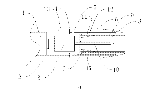
Provided by the present invention is an electric heating device, comprising: a protective cover, provided with a protective cover inner protrusion and a protective cover outer protrusion; a heating chamber, wherein the bottom thereof employs a structure which gradually shrinks and closes up, and the chamber comprises a heating chamber outer wall and a heating chamber inner wall, the heating chamber outer wall being provided with a heating chamber outer wall inner protrusion, and the heating chamber inner wall being provided with a heating chamber inner wall outer protrusion; and a heating device, located in the heating chamber. The heating chamber outer wall inner protrusion is engaged with the protective cover outer protrusion, and the heating chamber inner wall outer protrusion is engaged with the protective cover inner protrusion. The present invention solves the technical problem in existing technology of a contact wearing out and loosening causing a heating chamber to move laterally, which easily causes burns and tobacco falling out when a cigarette is lifted, and thus the invention achieves the technical effects of effectively preventing a contact from wearing out, improving safety, and preventing tobacco from falling out.


French Abstract

La présente invention concerne un dispositif de chauffage électrique, comprenant : un couvercle de protection, pourvu d'une saillie interne de couvercle de protection et d'une saillie externe de couvercle de protection ; une chambre de chauffage, dont le fond utilise une structure qui rétrécit progressivement et se ferme, et la chambre comprend une paroi externe de chambre de chauffage et une paroi interne de chambre de chauffage, la paroi externe de chambre de chauffage étant pourvue d'une saillie interne de paroi externe de chambre de chauffage, et la paroi interne de la chambre de chauffage étant pourvue d'une saillie externe de paroi interne de chambre de chauffage ; et un dispositif de chauffage, situé dans la chambre de chauffage. La saillie interne de paroi externe de chambre de chauffage est en prise avec la saillie externe du couvercle de protection, et la saillie externe de paroi interne de chambre de chauffage est en prise avec la saillie interne du couvercle de protection. La présente invention résout le problème technique dans la technologie existante de l'usure d'un contact et de desserrage amenant une chambre de chauffage à se déplacer latéralement, ce qui provoque facilement des brûlures et la chute de tabac lorsqu'une cigarette est soulevée, et l'invention permet ainsi d'obtenir les effets techniques de prévention efficace de l'usure d'un contact, d'amélioration de la sécurité et de prévention de la chute de tabac.

Claims

Note: Claims are shown in the official language in which they were submitted.


CA 03117835 2021-04-27
WHAT IS CLAIMED IS:
1. An electric heating device, wherein comprising: a protective cover provided
with
inner protrusions of the protective cover and outer protrusions of the
protective cover; a
heating cavity, the bottom of the heating cavity adopting a closing structure
that is
gradually narrowed, including an outer wall of the heating cavity and an inner
wall of the
heating cavity, the heating cavity outer wall being provided with protrusions
on the
heating cavity outer wall, the heating cavity inner wall being provided with
protrusions on
the heating cavity inner wall; and a heating means located in the heating
cavity;
the inner protrusions on the heating cavity outer wall being snap-fitted with
the outer
protrusions of the protective cover, and the outer protrusions on the heating
cavity inner
wall being snap-fitted with the inner protrusions of the protective cover.
2. The electric heating device according to claim 1, wherein the heating
appliance
comprises a heating means and a controller; the heating cavity rotates around
the
heating means.
3. The electric heating device according to claim 2, wherein the heating
cavity
rotates around the heating device, and a rotation angle is between 0-360 .
4. The electric heating device according to claim 3, wherein the heating
cavity
rotates around the heating device, and the rotation angle is between 60-300 .
5. The electric heating device according to any one of claims 2-4, wherein
after the
.. heating cavity and the heating appliance are fixed to each other, the
heating cavity fails
or is difficult to be removed from the heating appliance without external
force or other
actions.
6. The electric heating device according to any one of claims 1-5, wherein the
heating cavity is capable to be removed with a smaller external force when
rotating from
.. a first position to a second position.
7. The electric heating device according to any one of claims 1-6, wherein the
closing
structure that is gradually narrowed starts closing at any position in the
heating cavity.
8. The electric heating device according to claim 7, wherein the position to
be closed
of the heating cavity starts from an area containing the heating means in the
heating
.. cavity.
9
Date Regue/Date Received 2021-01-22

CA 03117835 2021-04-27
9. The electric heating device according to any one of claims 1-8, wherein the
closing
structure that is gradually narrowed is a linear closing that is gradually
narrowed.
10. The electric heating device according to any one of claims 1-8, wherein
the
closing structure that is gradually narrowed is an arc-shaped structure that
is gradually
narrowed.
l()
Date Regue/Date Received 2021-01-22

Description

Note: Descriptions are shown in the official language in which they were submitted.


CA 03117835 2021-04-27
ELECTRIC HEATING DEVICE FOR PREVENTING CONTACT WEAR
AND TOBACCO FALLING
TECHNICAL FIELD
[0001] The present disclosure relates to the technical field of novel tobacco,
and in
particular, to an electric heating device for preventing contact wear and
tobacco falling.
BACKGROUND
[0002] In the field of heating non-combustion low-temperature cigarettes, the
tobacco
is heated by an external heat source, and the heating temperature is much
lower than
the burning temperature of cigarettes. In this way, the heating low-
temperature cigarettes
can significantly reduce a large number of harmful substances produced by
cigarette
burning, and it also can reduce harm of second-hand smoke to non-smokers. In a
new
type of cigarette where the tobacco product is heated by the external heat
source heats,
the tobacco product is heated to the atomization temperature to achieve the
effect of
generating smoke. In the above-mentioned new type cigarette where the tobacco
product is heated by the external heat source, it is necessary to separate the
cigarette
and the heater from the heating cavity after the cigarette is heated.
Therefore, it is
necessary to provide the cigarette taking structure of the electric heating
low-temperature
cigarette appliance to prevent the cigarettes from being heated out and
prevent the
tobacco from staying in the heating cavity.
[0003] Currently, US Patent No. 5,144,962 describes an example of a heated
smoking
system. The advantages of these systems as an example are that they reduce
sidestream smoke while allowing smokers to selectively suspend and restart
smoking.
U.S. Patent No. 5,144,962 includes a flavor generating medium in contact with
a heater
in one embodiment; when the medium is exhausted, both it and the heater are
replaced.
Date Regue/Date Received 2021-01-22

CA 03117835 2021-04-27
Further, the electric heating device disclosed in the prior art includes the
extractor for
aerosol generating device proposed by Philip Morris Manufacturing Company in
W02013076098A3 PCT patent, in which the sliding receiver is in the sleeve and
slidable
between a first position and a second position. In the first position, the
aerosol-forming
matrix of the smoking article is positioned so as to be heated by the heater,
and in the
second position, the aerosol-forming matrix is substantially separated from
the heater.
The sliding receiver includes a support to support the aerosol-forming matrix
of the
smoking article as the sliding receiver and the smoking article are moving
from the first
position to the second position. It can be seen that this structure separates
the cigarette
from the heating cavity after the heating device is separated from the heated
cigarette
through a movement between the first position and the second position.
[0004] There are three very important technical problems in the prior art.
First, the
electric heating device described in the above prior art needs to make the
heating cavity
housing of the heating rod, the smoke lifting structure and the like laterally
displaced
relative to the heating device, and the position is limited by one or more
contacts. Due to
long-term use and lateral displacement, the contact in the electric heating
device is
seriously worn out, which is easy to cause the contact to loosen, and the
cigarette lifting
structure is prone to lateral displacement, which in turn drives the cigarette
to loosen,
and even causes the cigarette in a heated working stage to be separated from
the
heating element. The separated cigarettes can no longer be effectively
inserted into the
heating element, which greatly reduces the consumer experience. Second, the
temperature in the heating cavity after heating exceeds 100 C , and the
heating element
temperature is higher. After the lateral displacement of the heating cavity
housing and
the smoke lifting structure, the parts close to the heating element or even
the heating
element are exposed, which may easily cause burns and other injuries. Third,
when
using the extraction structure in the aforementioned W02013076098A3 PCT patent
to
2
Date Regue/Date Received 2021-01-22

CA 03117835 2021-04-27
extract cigarettes, there will be cases where the tobacco ends after being
heated will fall
off, so that after a certain period of use, the remaining tobacco will
accumulate in the
heating cavity, affecting with subsequent heating and suction effects, the
cleaning
frequency will also be greatly increased.
SUMMARY
[0005] The purpose of the present disclosure is to overcome the above-
mentioned
shortcomings and solve the above-mentioned technical problems. The present
disclosure proposes an electric heating device that can prevent contact wear,
improve
safety and prevent tobacco falling.
[0006] An electric heating device includes: a protective cover provided with
inner
protrusions of the protective cover and outer protrusions of the protective
cover; a
heating cavity, the bottom of the heating cavity adopts a closing structure
that is gradually
narrowed, and includes an outer wall of the heating cavity and an inner wall
of the heating
cavity, the heating cavity outer wall is provided with protrusions on the
heating cavity
outer wall, the heating cavity inner wall is provided with a protrusions on
the heating
cavity inner wall; and a heating means located in the heating cavity; the
inner protrusions
on the heating cavity outer wall match with the outer protrusions of the
protective cover,
and the outer protrusions on the heating cavity inner wall match with the
inner protrusions
of the protective cover.
[0007] Further, the electric heating device includes a heating appliance, and
the
heating appliance includes a heating means and a controller; the heating
cavity rotates
around the heating means.
[0008] Preferably, the heating cavity rotates around the heating device, and a
rotation
angle is between 0-3600 , and more preferably, the rotation angle is between
60-3000 .
3
Date Regue/Date Received 2021-01-22

CA 03117835 2021-04-27
[0009] Further, after the heating cavity and the heating appliance are fixed
to each other,
the heating cavity fails or is difficult to be removed from the heating
appliance without
external force or other actions.
[0010] Optionally, the heating cavity is capable to be removed with a smaller
external
force when rotating from a first position to a second position. The first
position is a
position where the inner protrusions on the heating cavity outer wall and the
outer
protrusions of the protective cover are fully snap-fitted, and the second
position is a
position having a smaller snap-fitted area than the snap-fitted area when the
inner
protrusions on the heating cavity outer wall and the outer protrusions of the
protective
cover are fully snap-fitted. Preferably, the second position is a position
where the inner
protrusions on the heating cavity outer wall and the outer protrusions of the
protective
cover are not snap-fitted at all.
[0011] Further, the closing structure that is gradually narrowed starts
closing at any
position in the heating cavity.
[0012] Preferably, the closing position of the heating cavity of the closing
structure that
is gradually narrowed starts from an area containing the heating means in the
heating
cavity.
[0013] Further, the closing structure that is gradually narrowed is adopted by
the bottom
of the heating cavity, the heating cavity can be closed from any position of
the heating
cavity.
[0014] Preferably, the closing position of the heating cavity can start from
an area
containing the heating means in the heating cavity.
[0015] Optionally, the closing structure that is gradually narrowed is a
linear closing or
a an arc-shaped structure that is gradually narrowed.
.. [0016] To sum up, first of all, the present disclosure adds two sets of
mutually matched
4
Date Regue/Date Received 2021-01-22

CA 03117835 2021-04-27
protrusions, so that the heating cavity can rotate around the heating means.
It is
impossible or difficult to remove the heating cavity from the heating
appliance without
external force or other actions, thereby avoiding the lateral displacement of
the smoke
lifting structure relative to the heating device, and effectively preventing
the heating rod
from being easy to loose and falling off the smoke lifting structure after
long-term use,
and even driving the cigarette to fall off. The risk of burns and other
injuries caused by
high-temperature locations such as heating means are greatly reduced.
Secondly, a
closing structure that is gradually narrowed is adopted at the bottom of the
heating cavity
(the cavity where the cigarette is inserted), to deform and shrink the end of
the cigarette.
By wrapping the tobacco through the cigarette paper outside the cigarette, it
can
effectively prevent the tobacco in the end of the cigarette falling off, which
effectively
improves the suction effect and greatly reduces the frequency of consumers
cleaning the
heating cavity.
DESCRIPTION OF THE DRAWINGS
[0017] The accompanying drawings are used to provide a further understanding
of the
present disclosure, and constitute a part of the specification, together with
the following
specific embodiments to explain the present disclosure, but does not limit the
present
disclosure. In the attached figures:
[0018] Fig. 1 illustrates a schematic cross-sectional view of a first
embodiment
according to the present disclosure;
[0019] Fig. 2 illustrates a schematic cross-sectional view of a second
embodiment
according to the present disclosure.
[0020] In the figures:
[0021] 1, battery; 2, housing; 3, controller; 4, inner protrusion on the
heating cavity outer
5
Date Regue/Date Received 2021-01-22

CA 03117835 2021-04-27
wall; 5, outer protrusion on the protective cover; 6, heating cavity outer
wall; 7, linear
closing; 8, heating cavity; 9, heating cavity inner wall; 10, heating means;
11, outer
protrusion of the heating cavity inner wall; 12, inner protrusion of the
protective cover;
13, control key; 14, arc-shaped closing; 15, protective cover.
DETAILED DESCRIPTION OF EMBODIMENTS
[0022] Embodiment 1
[0023] Fig. 1 shows an electric heating device for an electronic cigarette as
an
embodiment according to the present disclosure. The electric heating device
can be
placed in the main power supply box or directly charged with an external power
source
as a separate electric heating device. The electric heating device may include
a battery
1, a housing 2, a controller 3, and control keys 13. In the embodiment, the
electric heating
device may include a heating cavity outer wall 6, a heating cavity inner wall
9, a heating
means 10, and a protective cover 15 for protecting the heating device. The
heating cavity
outer wall 6 may be provided with inner protrusions 4 on the heating cavity
outer wall,
and the inner protrusions 4 of the heating cavity outer wall may be matched
with the
outer protrusions 5 of the protective cover in a snap-fitted manner. The
heating cavity
inner wall 9 may be provided with an outer protrusion 11 on the heating cavity
inner wall,
and the outer protrusions 11 of the heating cavity inner wall may be matched
with the
inner protrusions 12 of the protective cover in a snap-fitted manner. As shown
in Fig. 1,
the heating cavity 8 of the electric heating device is connected to a heating
appliance
including a heating means 10 and a controller 3 through a buckle, and the
heating cavity
8 can rotate around the heating means 10. At this time, after the heating
cavity is snap-
fitted with the heating appliance through the buckle, the heating cavity 8 and
the heating
appliance are integrated as a whole, and the heating cavity 8 cannot or is
difficult to
remove from the heating appliance without external force or other actions. The
heating
6
Date Regue/Date Received 2021-01-22

CA 03117835 2021-04-27
cavity 8 can rotate around the heating means 10, and the rotation angle is
between 0
and 3600 , for example, it can be 60 , 1000 , or 3000 . The bottom of the
heating cavity
8 adopts a closing structure that is gradually narrowed. The closing position
of the
heating cavity 8 can start to close from any position in the heating cavity.
Preferably, the
closing position of the heating cavity 8 can start from any area in the
heating cavity that
contains heating means. As shown in Fig. 1, the closing of the heating cavity
8 can adopt
a linear closing 7.
[0024] Embodiment 2
[0025] Fig. 2 shows an electric heating device for an electronic cigarette as
another
embodiment according to the present disclosure. The above electric heating
device can
be placed in the main power box or directly charged with an external power
source as a
separate electric heating device. The electric heating device may include a
battery 1, a
casing 2, a controller 3, and control keys 13. In the embodiment, the electric
heating
device includes a heating cavity outer wall 6, a heating cavity inner wall 9,
a heating
means 10, and a protective cover 15 for protecting the heating device. The
heating cavity
outer wall 6 may be provided with inner protrusions 4 on the heating cavity
outer wall,
and the inner protrusions 4 of the heating cavity outer wall may be matched
with the
outer protrusions 5 of the protective cover in a snap-fitted manner. The
heating cavity
inner wall 9 may be provided with outer protrusions 11 on the heating cavity
inner wall,
and the outer protrusions 11 of the heating cavity inner wall may be matched
with the
inner protrusions 12 of the protective cover in a snap-fitted manner. As shown
in Fig. 1,
the heating cavity 8 of the electric heating device may be connected to a
heating
appliance including a heating means 10 and a controller 3 through a buckle,
and the
heating cavity 8 can rotate around the heating means 10. At this time, after
the heating
cavity is snap-fitted with the heating appliance through the buckle, the
heating cavity 8
and the heating appliance are integrated as a whole, and the heating cavity 8
cannot or
7
Date Regue/Date Received 2021-01-22

CA 03117835 2021-04-27
is difficult to remove from the heating appliance without external force or
other actions.
The heating cavity 8 can rotate around the heating means 10, and the rotation
angle is
between 0 and 360 , for example, it can be 70 or 120 . A closing structure
that
is gradually narrowed may be adopted in the bottom of the heating cavity 8.
The closing
position of the heating cavity 8 can start to close from any position in the
heating cavity.
Preferably, the closing position of the heating cavity 8 can start from any
area in the
heating cavity that contains heating means. As shown in Fig. 2, the closing of
the heating
cavity 8 adopts an arc-shaped closing 14.
[0026] The preferred embodiments of the present disclosure are described in
detail
above, but the present disclosure is not limited to the specific details in
the aforesaid
embodiments. Various simple modifications can be made to the technical
solution of the
present disclosure within the scope of the technical concept of the present
disclosure,
and these simple modifications all fall within the protection scope of the
present
disclosure.
[0027] In addition, it should be understood that the various specific
technical features
described in the aforesaid specific embodiments can be combined in any
suitable
manner without contradiction. In order to avoid unnecessary repetition, the
various
possible combinations are not described separately in the present disclosure.
8
Date Regue/Date Received 2021-01-22

Representative Drawing
A single figure which represents the drawing illustrating the invention.
Administrative Status

2024-08-01:As part of the Next Generation Patents (NGP) transition, the Canadian Patents Database (CPD) now contains a more detailed Event History, which replicates the Event Log of our new back-office solution.

Please note that "Inactive:" events refers to events no longer in use in our new back-office solution.

For a clearer understanding of the status of the application/patent presented on this page, the site Disclaimer , as well as the definitions for Patent , Event History , Maintenance Fee  and Payment History  should be consulted.

Event History

Description Date
Letter Sent 2024-07-03
Notice of Allowance is Issued 2024-07-03
Inactive: Approved for allowance (AFA) 2024-06-26
Inactive: Q2 passed 2024-06-26
Amendment Received - Voluntary Amendment 2024-02-27
Amendment Received - Response to Examiner's Requisition 2024-02-27
Examiner's Report 2023-10-30
Inactive: Report - No QC 2023-10-27
Amendment Received - Response to Examiner's Requisition 2023-06-23
Amendment Received - Voluntary Amendment 2023-06-23
Examiner's Report 2023-02-24
Inactive: Report - No QC 2023-02-23
Amendment Received - Response to Examiner's Requisition 2022-12-07
Amendment Received - Voluntary Amendment 2022-12-07
Amendment Received - Response to Examiner's Requisition 2022-12-05
Amendment Received - Voluntary Amendment 2022-12-05
Examiner's Report 2022-08-03
Inactive: Report - QC passed 2022-07-11
Common Representative Appointed 2021-11-13
Inactive: Cover page published 2021-05-26
Letter sent 2021-05-20
Inactive: IPC assigned 2021-05-14
Inactive: IPC removed 2021-05-14
Inactive: First IPC assigned 2021-05-14
Inactive: IPC assigned 2021-05-14
Inactive: First IPC assigned 2021-05-13
Letter Sent 2021-05-13
Inactive: IPC assigned 2021-05-13
Application Received - PCT 2021-05-13
National Entry Requirements Determined Compliant 2021-04-27
Request for Examination Requirements Determined Compliant 2021-04-27
All Requirements for Examination Determined Compliant 2021-04-27
Application Published (Open to Public Inspection) 2020-01-30

Abandonment History

There is no abandonment history.

Maintenance Fee

The last payment was received on 2024-06-25

Note : If the full payment has not been received on or before the date indicated, a further fee may be required which may be one of the following

  • the reinstatement fee;
  • the late payment fee; or
  • additional fee to reverse deemed expiry.

Patent fees are adjusted on the 1st of January every year. The amounts above are the current amounts if received by December 31 of the current year.
Please refer to the CIPO Patent Fees web page to see all current fee amounts.

Fee History

Fee Type Anniversary Year Due Date Paid Date
Basic national fee - standard 2021-04-27 2021-04-27
Request for examination - standard 2023-07-24 2021-04-27
MF (application, 2nd anniv.) - standard 02 2020-07-23 2021-04-27
Reinstatement (national entry) 2021-04-27 2021-04-27
MF (application, 3rd anniv.) - standard 03 2021-07-23 2021-05-31
MF (application, 4th anniv.) - standard 04 2022-07-25 2022-06-07
MF (application, 5th anniv.) - standard 05 2023-07-24 2023-06-12
MF (application, 6th anniv.) - standard 06 2024-07-23 2024-06-25
Owners on Record

Note: Records showing the ownership history in alphabetical order.

Current Owners on Record
CHINA TOBACCO HUBEI INDUSTRIAL CORPORATION LIMITED
Past Owners on Record
CHENGHAO LUO
HUACHEN LIU
LONG HUANG
WEICHANG KE
YIKUN CHEN
Past Owners that do not appear in the "Owners on Record" listing will appear in other documentation within the application.
Documents

To view selected files, please enter reCAPTCHA code :


To view images, click a link in the Document Description column. To download the documents, select one or more checkboxes in the first column and then click the "Download Selected in PDF format (Zip Archive)" or the "Download Selected as Single PDF" button.

List of published and non-published patent-specific documents on the CPD .

If you have any difficulty accessing content, you can call the Client Service Centre at 1-866-997-1936 or send them an e-mail at CIPO Client Service Centre.


Document
Description 
Date
(yyyy-mm-dd) 
Number of pages   Size of Image (KB) 
Claims 2024-02-26 2 75
Claims 2023-06-22 2 78
Claims 2021-04-26 2 129
Drawings 2021-04-26 2 200
Description 2021-04-26 8 759
Abstract 2021-04-26 1 44
Representative drawing 2021-04-26 1 16
Claims 2022-12-04 2 73
Fees 2024-07-23 1 94
Maintenance fee payment 2024-06-24 3 80
Commissioner's Notice - Application Found Allowable 2024-07-02 1 572
Amendment / response to report 2024-02-26 5 114
Courtesy - Letter Acknowledging PCT National Phase Entry 2021-05-19 1 586
Courtesy - Acknowledgement of Request for Examination 2021-05-12 1 425
Amendment / response to report 2023-06-22 8 253
Examiner requisition 2023-10-29 3 159
International Preliminary Report on Patentability 2021-04-26 13 560
National entry request 2021-04-26 7 292
Patent cooperation treaty (PCT) 2021-04-26 2 175
Amendment - Claims 2021-04-26 2 99
International search report 2021-04-26 4 127
Fees 2021-04-26 3 82
Examiner requisition 2022-08-02 6 333
Amendment / response to report 2022-12-04 9 219
Amendment / response to report 2022-12-06 4 195
Examiner requisition 2023-02-23 3 165