Note: Descriptions are shown in the official language in which they were submitted.
CA 03118038 2021-04-28
1
Procedure for the filling of solids in pharmaceutical containers and the
sealing thereof under sterile
conditions
Field of the Invention
The present invention falls within the field of filling and sealing under
sterile conditions of
pharmaceutical containers including syringes, vials, capsules, ampoules,
single-dose devices or
cartridges that have been filled with solid substances selected from the group
formed by powder,
granules, pellets, nanoparticles, or microparticles, obtaining the sealing of
these solid substances.
More particularly, the field of the invention relates to a procedure for the
filling and sealing of
pharmaceutical containers which have been filled with one or more sterile
solid pharmaceutical
substances or sterile excipients dispensed and prepared in an aseptic
environment which avoids
adherence of the said substances to the sides of the pharmaceutical
containers, thus ensuring the
tightness of the container seal.
Background Art
In the pharmaceutical industry, the filling process of pharmaceutical
containers is often carried out
with liquid pharmaceutical substances and/or freeze-dried solids, as these are
much easier to
handle and involve fewer dosing problems than solids such as powders,
granules, pellets,
nanoparticles, microparticles, and others. The use of solids such as those
mentioned above in the
container filling process has the major drawback that these solids tend to
adhere to the walls or
body of the containers, preventing or at least hindering the obtaining of the
necessary tightness in
the container seal. This adherence to the walls or to the body, in addition to
preventing the desired
tightness, leads to contamination of the containers and loss of doses, as
containers in which such
adherence to the walls is observed must be discarded because as part of the
solid remains in the
sealing area of the container walls, it is not possible to know the exact
amount of solid that will be
delivered to the patient. On the other hand, with regard to contamination, as
the dispensed solid
remains adhered to the walls of the sealing area, the stopper used to seal the
container does not
close hermetically, so it will not be able to prevent the entry of substances
from the environment
into the container and will not ensure the integrity of the product, such that
its physico-chemical
and microbiological properties may vary, affecting the quality of the
medicinal product. This is
the biggest drawback that the pharmaceutical industry can encounter in this
field due to the strict
conditions imposed by the regulations of the industry, which must also comply
with the standards
Date Recue/Date Received 2021-04-28
CA 03118038 2021-04-28
2
known as Good Manufacturing Practices (GMPs).
Another concern for the pharmaceutical industry is ensuring the integrity of
the closure, which
also affects safety, as small losses of the medicine can affect the safety of
the healthcare workers
handling it. The term integrity here refers to the physic ability of a
container closure system to
maintain product sterility and quality of final sterile pharmaceutical,
biological and vaccine
products throughout their lifetime. A sterile product is also defined as a
product free of micro-
organisms, whose composition is one or more of the elements exposed to aseptic
conditions and
which ultimately make up the sterile finished pharmaceutical product. These
elements include the
.. containers, closures, and components of the finished pharmaceutical
product.
When dosing powder into pharmaceutical containers, several factors affecting
the cleanliness of
the inner walls of the containers must be considered, as lack of cleanliness
results in contamination.
These factors are listed below:
- The static charge of the walls of the pharmaceutical containers used for
filling, as well as the
static charge of the solid that is dispensed into them: If the wall and solid
loads have opposite
charges, the dispensed solid will adhere to the container walls.
- The kinetic energy that both the dispensed solid and the elements in contact
with it acquire when
the solid falls into the containers: The greater the height from which the
solid to be dispensed falls
freely to the bottom of the containers, the greater the kinetic energy
acquired by the solid and the
elements due to friction.
The length of the dispenser needles (also known as nozzles) used for dosing,
as the longer the
dispenser is and the closer it is to the top of the dispensed solid in the
container, the less kinetic
energy it will have. In addition, the dispenser conveys the dispensed solid to
an area away from
the wall surfaces of the container used. The ideal distance between the
dispensed solid and the tip
of the dispenser will depend on the dispensing rate and the density of the
solid dispensed.
- Redirection of the air displaced inside the containers. This phenomenon is
related to the kinetic
energy of the dispensed solid when it is released into the container. During
dispensing, the inrush
of the solid into the container displaces the air inside the container
upwards. This displaced air is
full of suspended particles. Thus, the dispenser can be thought of as a
"chimney" that moves the
Date Recue/Date Received 2021-04-28
CA 03118038 2021-04-28
3
air stream away from the interior walls, preserving them from this
contamination.
- The use of large airflow streams (unidirectional or turbulent regime) in
filling cabins or filling
sites as required by international Pharmacopoeias to ensure the removal of any
foreign particles
that may contaminate the final product from the aseptic filling and sealing
process. The use of
these airflow streams makes filling with solids quite difficult, as a
disturbance is generated that
causes the solid to adhere to the walls of the container used for filling.
In order to eliminate the adherence of the solid to the walls of the
container, one of the measures
used is to perform a process of ionisation of both the container and the solid
to be filled in it. In
the present invention, the terms "process", "stage" and "phase" are used
interchangeably, as well
as the terms "ionisation" and "deionisation" or "ioniser" and "deioniser".
Ionisation is a chemical or physical phenomenon by which ions are produced.
Ions are atoms or
molecules that are electrically charged due to an excess or lack of electrons
relative to a neutral
atom or molecule. The chemical species with more electrons than the neutral
atom or molecule is
called an anion, having a net negative charge, and the one with fewer
electrons is called a cation,
having a net positive charge.
The ionisation process employed in the present invention is used both to
neutralise the electrostatic
charge of the pharmaceutical container to be filled with the pharmaceutical
solid, and to neutralise
the electrostatic charge of the solid to be dispensed, i.e., for both the
container and the contents.
This ionisation is also used to neutralise the elements of the dosing and
capping equipment that
come into contact with the container and/or the powder. For this purpose, the
ioniser generates
ions of both polarities which are projected onto the surface of the object to
be neutralised, where
ions of opposite signs are recombined and those of the same sign are rejected.
Throughout this
document, "ioniser" means any element or device which is capable of ionising
the surrounding air
molecules, so that they are then projected onto a surface which has static
electrical charges that
neutralise those charges, thereby ionising that surface.
However, with this ionisation process only it is not possible to avoid the
serious problem of
adherence to the sides of the container during the process of filling the
containers with solids,
because when the solid is filled through the nozzle, the kinetic energy
carried by the solid generates
turbulence inside the container that eventually again causes part of the solid
to stick to the walls
Date Recue/Date Received 2021-04-28
CA 03118038 2021-04-28
4
or the body of the container.
As regards the prior art, the documents cited below describe the ionisation
technique that results
in the neutralisation of electrical charges applied to various situations:
In this regard, patent US 2016/0200461 Al filed by VANRX Pharmasystems INC.
describes a
method for volumetric filling and aseptic sealing of containers such as vials,
bottles, syringes and
ampoules with a liquid pharmaceutical product (which can be subsequently
lyophilised) in a
controlled environment. This publication mentions concerns about the materials
from which the
containers are made, whether glass or polymeric materials. On one hand, glass
containers suffer
from breakage, scratching, and particle emission due to collisions between
them. On the other
hand, containers made of polymeric materials are more resistant than those
made of glass, although
they suffer from cosmetic defects such as scratches, which can impair the
quality of the
pharmaceutical product due to collisions.
A substantial difference in the present invention with respect to the document
cited is that the
compounds handled are solid substances that are much more difficult to dose,
since they are highly
charged and have a higher specific surface area. Moreover, in the above-
mentioned document the
sealing process comprises two stages, a partial stage and a second complete
stage due to the need
for freeze-drying after the first partial sealing, whereas in the present
invention the sealing process
is carried out in a single stage with a complete sealing, without the need to
resort to subsequent
sealing stages.
In addition, it should be noted that the filling process of solid substances
is much more complex
due to the fact that the solid substances remain adhered to the walls of the
pharmaceutical
containers, impairing the precision of the dosage, which is more relevant in
small calibre
containers where it is necessary to dose small quantities of medicines in a
very precise way. This
drawback is solved by the procedure proposed in the present invention, since
it must be taken into
account that, in the pharmaceutical industry, an error in the filling of the
active ingredient may
mean that patients will receive an incorrect dose of the product.
This is a serious drawback when filling containers with solids due to the
problem of the adherence
of the solid to the body of the containers. For this reason, in most of the
procedures used today in
the pharmaceutical industry, certification of the equipment is mandatory to
ensure that the
Date Recue/Date Received 2021-04-28
CA 03118038 2021-04-28
dispensed quantity is adequate. In addition, various in-process controls are
incorporated during
packaging to verify the actual filling quantity of all pharmaceutical
containers. A common control
is weighing the containers, which allows to rectify or discard containers in
which the quantity of
pharmaceutical substance, either drug or active ingredient, does not meet the
required weighing
5 accuracy. In-process controls can be 100% or statistical; the latter are
carried out from time to time
to check the dosage. These controls involve a high production and economic
cost, which is
necessary to control the precision of the product dosage.
As for the elimination of electrostatic charge, several types of ionisers are
available for dealing
with this problem. These ionisers come in various shapes, such as ring, rod,
gun, curtain, blade,
barrel, needle, or filter ionisers, including isolators with an ioniser on the
top of the isolator, among
others. For the purpose of this invention, these ionisers can be installed on
the machinery used for
the filling process to produce ions of both polarities that neutralise the
surface of the containers or
products, or they can also be placed in the packaging areas, room or
isolators, specifically on the
.. ceiling of the isolators to produce an ionisation that neutralises both the
environment and the air
flow of the area, thereby eliminating the problem of static charges.
With regard to the removal of the static charge of solids by ionisers, several
documents are cited
below:
European patent EP 2711096 A2 applied for by TRINC Corporation relates to a
device for the
removal of electrostatic charge and dirt from objects such as film, foil,
glass, clothing, paper or the
like. The device comprises a large container with an opening at the top and an
opening at the
bottom for suctioning and discharging the powder and a small cylindrical or
conical container
inside the large container. This small container is designed to generate a
cyclone current and
tornado current within it, and comprises at least one corona discharge ion
generator. This ion
generator consists of electric discharge needles that are placed either on top
of or inside the small
container. The small container comprises air injection openings through which
compressed air is
injected, as well as ultrasound generators inside or outside the small
container meant to make the
powder vibrate so that it can be separated from the desired object once it has
been neutralised by
the ion generator. This powder can be collected by vacuum suction inside the
large container.
The present invention, instead, relates to the deionisation of both the
container and the powder
prior to packaging in order to prevent the powder from sticking to the
container walls during the
Date Recue/Date Received 2021-04-28
CA 03118038 2021-04-28
6
filling process and thus to achieve a complete seal. In addition, as a safety
factor, deionisation is
carried out on and/or inside the container to remove any remaining powder
adhered to the walls of
the sealing area.
The present invention also uses an ioniser, whether in the form of a ring,
rod, gun, curtain, blades,
barrel, needle or nozzle, or an ionising filter, including isolators with an
ioniser on the top of said
isolator, to eliminate static electricity, but it does so both on the powdered
solid and the container
to be used, which is not done in European patent EP 2711096 A2, as this only
ionises the powder
and does not ionise the container. Another substantial difference of the
present invention with said
document is based on the fact that said European patent EP 2711096 uses
compressed air to
facilitate suction, whereas the present invention does not need an air stream
and, if it does, it should
be of a sterile carrier gas. Among sterile carrier gases, an ionised nitrogen
stream has advantages
which will be discussed below.
A characteristic drawback of the present invention is the need to carry out
the deionisation in sterile
environments, making the use of sterile carrier gases necessary. It should be
noted that this sterile
condition of the carrier gas does not affect the deionisation process.
On the other hand, European patent EP 2711096 A2 differs from the present
invention in that,
.. although in both it is important to eliminate the electrostatic charge of
the solid, said document
does not discuss in detail the method by which this is carried out, mentioning
only the use of an
ion generator such as discharge needles for deionisation, without mentioning
the problem caused
by the electric discharge needles when they approach any solid, namely the
appearance of a
combustion phenomenon burning the product, generating impurities and altering
the
physicochemical composition of the product.
Japanese patent JP 2005001818 A applied for by YMS IU( refers to a powder
supply device and
an air conveying device capable of feeding easily-charged powder and charged
powder. This
device comprises a hopper equipped with aeration means that are in turn
equipped with a
microporous diaphragm to aerate the powder in the hopper. The air for aeration
is pre-ionised by
an ionisation device such as a corona discharge device. Compressed air
supplied by an air
compressor is used for aeration. This compressed air is ionised by an air
ionisation device
comprising a corona discharge device or the like. When the aeration is
performed by ionised air,
the ionised air neutralises or removes the surface charge of the powder, so
that the surface charge
Date Recue/Date Received 2021-04-28
CA 03118038 2021-04-28
7
of the charged powder disappears. In addition, when aeration causes the powder
in the hopper to
inflate air and a layer of air forms between the powder and the inner wall of
the hopper, the powder
is prevented from becoming charged again. In addition, this document refers to
a suction nozzle
or needle made of conductive material that forms part of the air conveying
device. This nozzle is
never a dosing nozzle.
In the present invention, on the other hand, the solid substance is ionised on
one hand and the
pharmaceutical container is ionised on the other hand, using a sterile carrier
gas stream as the
ionised gas, usually a stream of sterile nitrogen. Another difference of the
present invention with
this Japanese patent is in the nozzle or needle; in the case of this Japanese
patent, it refers to a
suction nozzle made of conductive material, whereas, in the present invention,
the nozzle is a
dispensing needle and is not made of conductive material. In contrast to this
Japanese patent, the
present invention also uses an ioniser, whether in the form of a ring, rod,
gun, curtain, blades,
barrel, needle or nozzle, or an ionising filter, including isolators with an
ioniser on the top of the
isolator or of any other type, in order to neutralise the electrostatic charge
of both the container to
be filled and the solid to be dispensed, whereas the Japanese patent only
mentions the use of a
corona discharge ionising device or the like.
Chinese utility model CN 203265193U by Meech Static Eliminators Shanghai Co
LTD makes
reference to the technical field of static electricity and powder removal from
the inner wall of
bottles, prior to filling, for container cleaning, using for this purpose an
ion needle with compressed
air to eliminate static electricity and remove the powder adhering to the
walls of the bottle. The
device described in this utility model consists of a needle, a first tube
connecting the needle and a
second tube for connecting the electrical cable, the two ends of which have an
internal thread or
an external thread respectively. The needle tip and the second tube are
screwed and fixed together,
and the needle tip, the first tube and the second tube have an interconnected
inner passage for the
passage of air, and the second tube also has at least two threads, so that the
passage thread is also
connected to the inner bore of the first tube. The tube features unifoimly
spaced wire holes between
the inner and outer wall, each of these holes forming an ion-generating end at
one extreme of the
second tube that fits into the first member of the tube. The ions can be
introduced into the surface
of the proposed object through the ion needle and with the help of compressed
air.
In the present invention, instead, the ioniser can be of any type, as a ring,
rod, gun, curtain, blades,
barrel, needle or nozzle, or even an ionising filter, among which can also be
found isolators with
Date Recue/Date Received 2021-04-28
CA 03118038 2021-04-28
8
an ioniser on the top of said isolator, without the need for it to be a needle
as specifically mentioned
in the Chinese utility model. Furthermore, this utility model is assisted by
compressed air to
displace the ions, whereas the present invention may or may not use a sterile
carrier gas stream,
which may consist of sterile compressed nitrogen or air, not only to
facilitate the ionisation process
.. by aiding the dosing of the solid but also to maintain the necessary
sterile conditions required for
these procedures in the pharmaceutical industry by generating an inert
atmosphere inside the
containers. On the other hand, the utility model relates to cleaning bottles
with powder prior to
filling, whereas the present invention relates to deionisation and cleaning of
walls after filling and
applies to smaller containers than bottles, such as syringes, vials, capsules,
ampoules, single-dose
_______ devices or cal tlidges, which are more difficult to fill with a
solid such as powder.
International patent WO 2016/185230 A2 filed by 3P Innovation Limited
describes an apparatus
and method for filling pharmaceutical containers such as syringes, vials,
capsules, cartridges and
blister packs with powdered pharmaceutical material by vibration. This
apparatus has a support
for the pharmaceutical container, a tank containing pharmaceutical powder,
this tank being in
contact with a nozzle or filling needle in charge of filling the
pharmaceutical container with the
pharmaceutical powder, and a piezo-electric vibration device. This document
relates to the
advantage of using a cylinder comprising an electrically conductive material,
which can be
grounded through the weighing cell, thereby helping dissipate the static
charge of plastic
pharmaceutical containers to achieve a better powder filling process without
compromising
cleanliness. However, the invention described in that document would not
require the material to
be electrically conductive, since it is a process for filling through the
mouth of the container, so
that the problem of sealing that occurs when filling from the back of the
container would not arise.
The present invention, on the other hand, concerns a process for sealing
pharmaceutical containers
which are filled with pharmaceutical solids, wherein such filling is carried
out under aseptic
conditions without the need for terminal sterilisation, whereas said
international patent WO
2016/185230 A2 describes filling through the mouth of the container as can be
seen in figure 2.
On the other hand, this international publication only mentions the filling of
plastic pharmaceutical
containers such as containers, whereas the present invention includes all
types of materials, such
as polymeric materials or glass, for the container. Furthermore, the
international publication
mentions a cylinder or puck with an electrically conductive material meant to
dissipate the static
charge of the pharmaceutical containers to be used, whereas, in the present
invention, the existence
of a cylinder acting as a support for the container is an optional element,
unrelated to the problem
Date Recue/Date Received 2021-04-28
CA 03118038 2021-04-28
9
to be solved, and which is also intended for various other functions, such as:
- The use of such an element for the handling of the container without
contact with same.
- The cylinder protects the process from air streams by being part of the
"exclusion hood".
- It is an element for vertical support of the container on the weighing
cell for accurate weighing.
Furthermore, in the present invention it is possible to use any ioniser,
whatever form it may take,
i.e. ring, bar, gun, curtain, blades, barrels, needle or nozzle, or an
ionising filter, among which can
also be isolators with an ioniser on the top of said isolator which can be
installed on the packaging
equipment prior to filling, during filling and after filling, using or not a
sterile carrier gas, whereas
the invention described in said international publication only deals with a
cylinder (puck) with
electrically conductive material that can dissipate the static charge of the
plastic container used
during filling.
Summary of the Invention
Accordingly, the problem to be solved in the present invention is to provide a
procedure for filling
pharmaceutical containers which may take the form of vials, capsules,
ampoules, single-dose
devices, inhalers, bottles, blister call" idges, sachets, bags, test tubes,
Eppendorf0 tubes and
syringes. The syringes of the present invention may have a needle, catheter
type cone, or Luer lock
type cone, i.e. with an unthreaded tip or with female or male threaded tip,
respectively. For the
purpose of the present invention, "Luer cone" refers to the cone-shaped tip
invented by Wiilfing
Luer with a typical taper of 6%, which can be male or female depending on the
coupling. Likewise,
-Luer lock cone" refers to the cone-shaped tip invented by the German Wiilfing
Luer with an
airtight threaded closure.
The compounds of the containers of the present invention are materials such as
plastics of different
composition, such as polyolefins and cyclopolyolefins, polypropylene,
polybutadiene,
polyethylene, polystyrene, polyvinyl chloride, polyacrylonitrile, polyamides,
etc., polyesters
(containing the ester functional group in their main chain: poly(ethylene
terephthalate),
polycarbonate), acrylic polymers (poly(methyl methacrylate),
polyacrylonitrile), thermoplastic
resins (polyacetals and polyhaloethylenes), polyurethanes, formaldehyde resins
(phenol resin, urea
Date Recue/Date Received 2021-04-28
CA 03118038 2021-04-28
resin), phenoplasts, aminoplasts, thioplasts, duroplastic resins (unsaturated
polyesters,
polyurethanes), polyvinylidene silicones, cellulose derivatives,
polycarbonates, and mixtures
thereof, etc. Alternatively, the container can also be made of metal, e.g.
steel or titanium suitable
for drug delivery, glass, etc., with solids in sterile conditions that
overcome the problems existing
5 in the state of the art, and in particular that prevent the solid from
adhering to the walls of the
container, while ensuring an airtight sealing of the container.
In turn, both the cylinder or puck, the hopper and the nozzle or needle will
preferably be composed
of various non-conductive materials such as various plastics, e.g. polyether
etherketone (PEEK),
10 .. glass, stone, resin, glass, but may also be composed of grounded
conductive materials such as steel
or titanium, etc.
Both the materials used for the container and the cylinder materials must be
watertight, inert, not
very permeable or impermeable, that do not absorb and/or adsorb the contained
product, not rough,
.. and free of particles.
The solution to the problem described in the present invention is based on the
fact that the inventors
have found that such a problem can be satisfactorily solved by means of the
following techniques,
which can be applied independently or in any combination:
On the one hand, ionising both the solid and the pharmaceutical container
where it is to be
deposited, as well as ionising the elements of the dosing and capping
equipment that comes into
contact with the container and/or the powder, at one or more stages of the
filling procedure, in
order to prevent the solid from tending to adhere to the walls of the
container, as well as the walls
.. of the container from tending to attract the solid particles, so that the
only tendency of the solid is
to fall to the bottom of the container and not be deposited on its walls. This
deionisation technique
can be applied to the container and the solid separately, as well as to the
container with product
inside. This deionisation can be applied as many times as there are filling
and capping steps in the
process;
On the other hand, by controlling the potential applied to the ionisers, which
should be such that
the resulting electrostatic charge on the container walls and/or the dispensed
solid is preferably
less than 2,000 V, more preferably less than 500 V, and most preferably less
than 200 V.
Date Recue/Date Received 2021-04-28
CA 03118038 2021-04-28
11
In addition, the filling of the pharmaceutical container with the solid is
preferably carried out using
a dispensing needle whose tip or dispensing end is located, throughout the
filling stage, at a height
between 1 to 3 mm above the surface of the solid deposited on the bottom of
the container, so as
to avoid turbulence that could lift the deposited solid towards the walls.
Even if this turbulence
phenomenon were to occur to some extent, ionisation of both the solid and the
inner walls of the
container will make said lifted particles settle back on the bottom of the
container, without
substantial loss of product on the container walls.
Consequently, in a first aspect the invention relates to a process for filling
under sterile conditions
pharmaceutical containers with solids, comprising the steps of:
a) providing a pharmaceutical container (1) having walls and a bottom,
b) dispensing the solid into the pharmaceutical container (1) by means of a
dispensing needle (4),
gravimetrically checking the weight of solid dispensed into the container (1);
and
c) sealing the pharmaceutical container with a stopper (6),
characterised in that, in at least one of steps a), b) and c), or a plurality
thereof in any combination,
the static electric charges on the inside walls of the container (1), on the
solid dispensed inside the
container, and/or on any parts in contact with the container walls or with the
solid dispensed inside
the container, are neutralised by means of an ioniser (2) to which an
ionisation potential is applied
such that the electrostatic charge inside the container (1) after each
ionisation is less than 2,000
volts. This ionisation prevents the solid dispensed into the container from
tending to adhere to the
inner walls of the container (1), which may distort the amount of solid
dispensed into the container,
hinder a visual assessment of the level of product dispensed, or even cause
incomplete
administration of the product to the patient.
In a second aspect, the invention relates to a container (1) containing a
solid product, wherein the
solid product has been dispensed into the container using the described
method.
In the case of ionisation in the rod/ring case, re-ionisation will be
performed preferably with a
needle with or without a gas stream.
In general, throughout the present description, filling is preferably carried
out by means of a
dispensing needle whose tip or dispensing end is located, throughout the
filling stage, at a height
Date Recue/Date Received 2021-04-28
CA 03118038 2021-04-28
12
of 1 to 3 mm above the surface of the solid deposited on the bottom of the
container, in order to
prevent generating turbulence that could lift the solid towards the walls of
the container.
This procedure has two advantages: On the one hand, achieving accuracy in the
filling of
substances into a single container even when two or more filling stations are
used, by preventing
the solid substances from sticking to the sides of the container. On the other
hand, ensuring the
integrity of the seal of the pharmaceutical container, which is especially
important in the case of
medicinal products as it prevents both the entry of foreign agents into the
container that would
contaminate the product, and the leakage of the product to the outside
affecting the effective dose
of the product.
Additionally, the present invention also solves the problem of static charges
generated by
collisions between the containers used for filling, whether they are made of
glass or polymeric
material, in a sterile environment that is generally subject to laminar or
turbulent flows which
increase the movement and dispersion of electrostatic charges.
Although the invention is generally applicable to powdered solid compounds of
any nature, this
procedure is particularly applicable to solids having the following particle
size distribution:
Dio > 20 microns
70 microns < D50 < 110 microns
150 microns < Do <215 microns
where Dio is the mean value of the particle size that divides the population
into exactly two equal
halves, with 50% of the distribution being above this value, and 50% below. In
general, throughout
this specification, a value denoted as "d0.X" or "Dx" represents the mass
fraction of the drug with
particle sizes below the specified value, having a range of 0.0 to 1Ø
According to this definition,
a value of d0.1 or Dio means that 10% of the total mass of the drug particles
has a particle size of
10 microns or less.
This is ideally applicable to solids having the following particle size
distribution:
Dio > 25 microns
100 microns < Dso < 155 microns
Date Recue/Date Received 2021-04-28
CA 03118038 2021-04-28
13
245 microns < Do < 325 microns
Examples of such compounds are risperidone, paliperidone, fentanyl,
olanzcompound activone,
letrozole, aripiprazole, anastrozole, asencompound activone, brexiprazole,
cariprazine,
clozcompound activone, iloperidone, lurasidone, queticompound activone,
ziprasidone, among
others including any derivatives, metabolites or salts (such as pamoate or
palmitate) alone or in
combination.
Other examples of such compounds are also biocompatible polymers of the
polylactic acid (PLA),
polyglycolic acid (PGA) types and their copolymers polylactic co-glycolic acid
(PLGA) including
any derivatives or copolymers, alone or in combination.
Brief description of the figures
The figures accompanying the present invention serve to illustrate the nature
of the invention.
These figures are included for purposes of illustration only and should not be
understood as
limiting the invention claimed herein. With respect to the ionisation
phenomenon, the present
invention proposes different methods, some of which are shown in figures 1 to
7 described below.
In order to properly interpret the figures, the ionisation phenomenon is
represented by the
alternating positive (+) and negative (-) signs, bearing in mind that this
stream of ions of different
signs may or may not be accompanied by a stream of sterile carrier gas,
although the latter is not
represented as such in the figures.
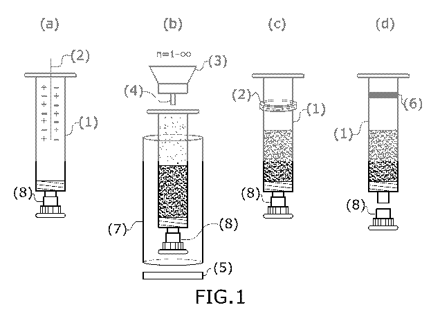
Figure 1: Figure 1 shows a particular embodiment of the aseptic filling and
sealing process
according to the present invention, wherein the pharmaceutical container
depicted is, in this case,
a male syringe (1) which remains capped with a nozzle cap (8) throughout the
process. The syringe
(1) is subjected to a first ionisation stage (a) with the aid of an ioniser
(2), with either a ring, rod,
gun, curtain, blade, barrel, needle or nozzle, or an ionising filter,
including isolators with an ioniser
on the top of the isolator, although in this case a needle ioniser is shown.
The male syringe (1) then
passes to the filling station (b), where the procedure of the invention may
comprise multiple filling
stations, in particular if there are multiple solids to be filled into the
syringe. In this station, the
syringe, which may optionally be inserted in a cylinder (7), is weighed by a
weighing cell (5)
during filling, which takes place by means of a hopper (3) and a nozzle or
dispensing needle (4).
After filling, the male syringe (1) is subjected to another ionisation stage
(c) by means of an ioniser
Date Recue/Date Received 2021-04-28
CA 03118038 2021-04-28
14
(2) provided at this stage either by a ring, rod, gun, curtain, blades,
barrels, needle or nozzle, or an
ionising filter, among which isolators with an ioniser on the top of the
isolator can also be found,
although in this case a ring ioniser is shown. Finally, the male syringe (1)
is transferred to a sealing
station (d) where it is hermetically sealed at the top with a stopper (6).
Figure 2: Shows another particular embodiment of the process of the present
invention, where the
male syringe of Figure 1 has been replaced by a female syringe as the
pharmaceutical container
(1).
Figure 3: Shows a particular embodiment of the process of the present
invention, where the syringe
has been replaced as the pharmaceutical container (1) by an Eppendorf0 tube,
which is subjected
to an ionisation stage (a) thanks to the presence in said stage of an ioniser
(2) whether it be a ring,
rod, gun, curtain, blades, barrels, needle or nozzle, or an ionising filter,
among which can also be
found isolators with an ioniser on the top of said isolator, in this case a
needle ioniser. It is then
transferred to the filling station (b) (there may be multiple filling
stations) where there is an ioniser
(2) with a ring, bar, gun, curtain, blades, barrel, needle or nozzle, or an
ionising filter, among which
there may also be isolators with an ioniser on the top of the isolator, in
this case an ionising filter.
In addition to the ioniser, this stage contains a weighing cell (5), a hopper
(3), and a nozzle or
dispensing needle (4). Finally, after filling, the Eppendorf0 tube is
subjected to an ionisation
process by means of a ring, rod, gun, curtain, blades, barrel, needle or
nozzle, or an ionising filter,
which may also include isolators with an ioniser on the top of the isolator,
in this case a rod ioniser
(2).
Figure 4: Shows a particular embodiment of the procedure of the present
invention in which the
container represented is, in this case, a syringe with needle (1) pre-capped
with the nozzle cap (8)
throughout the sealing process, which is subjected to a first ionisation
process (a) with the aid of
an ioniser (2) which may be in the form of a ring, bar, gun, curtain, blades,
barrel, needle or nozzle,
or an ionising filter, among which can also be found isolators with an ioniser
on the top of said
isolator, although in this case a needle ioniser is shown. The syringe with
needle (1) then passes
to the filling station (b), where in the procedure described in the present
invention there may be
multiple filling stations, in particular if there are multiple solids to be
filled into the syringe. In
said station, the syringe with needle, which may optionally be inserted in a
cylinder (7), is weighed
by a weighing cell (5) during filling, which takes place by means of a hopper
(3) and a nozzle or
dispensing needle (4). After filling, the syringe with needle (1) is subjected
to a further ionisation
Date Recue/Date Received 2021-04-28
CA 03118038 2021-04-28
step (c) by means of an ioniser (2), with either a ring, rod, gun, curtain,
blade, barrel, needle or
nozzle, or an ionising filter, including isolators with an ioniser on the top
of the isolator, although
in this case a ring ioniser is shown. Finally, the syringe with needle (1) is
transferred to a sealing
station (d) where it is hermetically sealed at the top with a stopper (6),
while it is subjected to an
5 .. additional ionisation stage by means of an ioniser (2) provided at this
step, with either a ring, rod,
gun, curtain, blades, barrels, needle or nozzle, or an ionising filter, among
which isolators with an
ioniser on the top of said isolator can also be found, in this case a rod
ioniser.
Figure 5: Shows another particular embodiment of the procedure of the present
invention in which
10 the container depicted is, in this case, a female syringe (1) capped
throughout the process with a
nozzle cap (8), which is subjected to a first ionisation process (a) with the
aid of an ioniser (2) with
either a ring, rod, gun, curtain, blade, barrel, needle or nozzle, or an
ionising filter. Next, the female
syringe (1) passes to the filling station (b), where in the procedure
described in the present
invention there may be multiple filling stations, in particular if there are
multiple solids to be filled
15 .. into the syringe. In said station, the syringe, which may optionally be
inserted in a cylinder (7), is
weighed by a weighing cell (5) during filling, which takes place by means of a
hopper (3) and a
nozzle or dispensing needle (4). After filling, the syringe undergoes an
ionisation process (c) by
means of an ioniser (2) in the form of a ring, rod, gun, curtain, blades,
barrels, needle or nozzle, or
an ionising filter, including isolators with an ioniser on the top of the
isolator, although in this case
a needle ioniser is shown. Finally, the female syringe (1) is transferred to a
sealing station (d)
where it is hermetically sealed at the top with a stopper (6) while it is
subjected to an additional
deionisation phase by means of an ioniser (2), provided at this stage, with
either a ring, rod, gun,
curtain, blade, barrel, needle or nozzle, or a filter ioniser, among which
there may also be isolators
with an ioniser on the top of the isolator, in this case, a rod ioniser.
Figure 6: Shows another particular embodiment of the procedure of the present
invention in which
the container represented is, on this occasion, a cathidge (1), is subjected
to a first ionisation
process (a) with the aid of an ioniser (2) with either a ring, rod, gun,
curtain, blades, barrel, needle
or nozzle, or an ionising filter, among which can also be found isolators with
an ioniser on the top
______________________________________________________________________ of said
isolator, although in the present case a needle ioniser is represented. The
cal ft idge (1) then
passes to the filling station (b), where in the procedure described in the
present invention there
may be multiple filling stations, particularly if there are multiple solids to
be filled into the
cartridge. In this station, the call" _______________________________________
idge is weighed by a weighing cell (5) during filling, which takes
place by means of a hopper (3) and a nozzle or dispensing needle (4). Finally,
the caftlidge (1),
Date Recue/Date Received 2021-04-28
CA 03118038 2021-04-28
16
which may optionally be inserted in a cylinder (7), is transferred to an
ionisation station where an
ioniser (2) will act, with either a ring, rod, gun, curtain, blades, barrel,
needle or nozzle, or an
ionising filter, or an isolator with an ioniser on the top of the isolator,
where in this case a rod
ioniser is shown.
Figure 7: Shows a particular embodiment of the process of the present
invention in which the
container represented is, in this case, a pre-filled female syringe (1) which
is first subjected to an
ionisation process (a) with the aid of an ioniser (2) with a ring, rod, gun,
curtain, blades, barrels,
needle or nozzle, or an ionising filter, among which can also be found
isolators with an ioniser on
the top of said isolator, although in the present case one with a ring is
represented. After this the
syringe, which is filled at its threaded end, is located in the filling
station (b), where in the process
described in the present invention there may be multiple filling stations,
particularly if there are
multiple solids to be filled into the syringe. In this station, the syringe,
which may optionally be
inserted in a cylinder (7), is weighed by a weighing cell (5) during filling,
which takes place by
means of a hopper (3) and a nozzle or dispensing needle (4). After filling,
the female syringe (1)
is subjected to a further ionisation phase (c) by means of an ioniser (2) with
either a ring, rod, gun,
curtain, blades, barrels, needle or nozzle, or an ionising filter, which may
also include isolators
with an ioniser on the top of the isolator (in this case a rod ioniser).
Detailed description of the invention
Filling of solid substances either by volumetric or gravimetric filling such
as powder, granules,
pellets, nanoparticles or microparticles in small pharmaceutical containers
such as vials, capsules,
ampoules, single-dose devices, inhalers, bottles, blister cartridges, sachets,
bags, test tubes,
Eppendorf0 type tubes and syringes (with male or female, threaded or non-
threaded nozzles) and
of different materials, such as plastics of different composition, such as
polyolefins and
cyclopolyolefins, polypropylene, polybutadiene, polyethylene, polystyrene,
polyvinyl chloride,
polyacrylonitrile, polyamides, etc., polyesters (containing the ester
functional group in its main
chain), poly(ethylene terephthalate), polycarbonate), acrylic polymers
(poly(methyl methacry late),
polyacrylonitrile), thermoplastic resins (polyacetals and polyhaloethylenes),
polyurethanes,
formaldehyde resins (phenol resin, urea resin), phenoplasts, aminoplasts,
thioplasts, duroplastic
resins (unsaturated polyester, polyurethanes), polyvinylidene silicones,
cellulose derivatives,
polycarbonates, and mixtures thereof, etc., where also alternatively the
container can be made of
metal, e.g. steel or titanium suitable for drug administration, or glass,
among others, is currently a
Date Recue/Date Received 2021-04-28
CA 03118038 2021-04-28
17
serious problem for the pharmaceutical industry due to the great drawback of
adherence of these
substances to the walls of the sealing area of the containers used. This
adherence results in
significant inconveniences for the cited industry, as it must comply with the
regulations indicated
in the various international Pharmacopoeias, in addition to complying with
good manufacturing
practices (GMP). The present invention addresses the drawbacks related to the
adhesion of said
solid substances to the walls of containers used for filling, as this adhesion
hinders both the filling
and the aseptic sealing processes. For the aseptic filling and sealing process
referred to in the
present invention, only solid substances such as those mentioned above are
used.
The international Pharmacopoeias require for aseptic filling and sealing the
presence of large air
flow streams (unidirectional or turbulent regime) to ensure the removal of any
extraneous particles
that may contaminate the final product. The use of these airflow streams makes
filling with solids
quite difficult, as a disturbance is generated that causes the solid to adhere
to the walls of the
container used for filling.
As the solid substances dispensed adhere to the walls of the container sealing
area, they are not
able to coalesce in the mouth area of the container, thus preventing the
necessary sealing from
being achieved. This lack of sealing leads to two serious problems: the loss
of doses of the solid
substance dispensed and the contamination of the container used for filling.
The loss of doses leads to inaccuracy in the administration of the
pharmaceutical product, as the
solid substances adhering to the walls of the container sealing area will be
measured by the
weighing cell indicating the precise amount of product to be administered to
the patient, but when
it is administered to the patient, they will receive a lower dose than
indicated, as the solid
substances adhering to the sides of the container will not be administered and
will remain stuck to
the sides of the container.
With regard to the contamination of the container that has been used for
filling, this is perhaps the
most serious of the drawbacks that can result from the lack of airtightness
caused by substance
adhering to the walls of the sealing area, as it affects the integrity of the
medicinal product and has
an impact on the health of the patient receiving the pharmaceutical product.
When sealing the
container with the stopper, if the walls of the container have solid
substances adhered to the sealing
area, these substances will remain in this area after the container is sealed,
which means that the
stopper cannot ensure the integrity of the sealed product, as any kind of
substance from the
Date Recue/Date Received 2021-04-28
CA 03118038 2021-04-28
18
environment could enter the product after the capping stage. Microbial
contamination is a very
serious issue for pharmaceutical companies, as their products are ideal
breeding grounds for micro-
organisms such as bacteria, fungi or yeasts. A theoretically sterile but
contaminated product can
lead to deterioration of the product, loss of the product's potential,
pyrogenic reactions after
administration to the patient, particularly in parenteral administration,
infection and colonisation
of micro-organisms in the patient, with the risk of secondary infection. Any
micro-organism,
whether pathogenic or non-pathogenic, found in a supposedly sterile
pharmaceutical product is a
hazard.
In view of the significant problems caused by the lack of sealing, the present
invention offers a
solution to the adherence of solid substances to the sides of the sealing area
of the pharmaceutical
container by achieving the sealing of said substance. Two methods are used to
promote the sealing
of the solid substances, namely the control of the height of the dispensing
needle and the ionisation
of both the pharmaceutical container used for filling and the solid substance
to be dispensed, as
well as the ionisation of the elements of the dispensing and capping equipment
that come into
contact with the syringe and/or the powder.
As mentioned in the section on the prior art, there are a number of factors
that affect the adhesion
of solids to the inner walls of the container, among which is the length of
the nozzle. The longer
the nozzle and the closer it is to the top level of powder in the container,
the less kinetic energy it
will have. In addition, the nozzle carries the powder away from the surface of
the sealing walls.
The inventors of the present invention have found that the ideal distance
between the powder and
the nozzle tip depends on the dosage, dispensing rate and density of the
powder, although typically
it is between 1 and 3 mm, more preferably around 2mm. The present invention
proposes several
options regarding the height of the nozzle:
-The first of these is based on having a nozzle with an exact height (h) of
the nozzle measured
from the bottom of the container. In this case, the filling process is carried
out at the rear of the
container, i.e. when the container is a syringe, at the mouth or end with the
largest diameter. A
minimum height h between the solid to be dispensed and the nozzle must always
be kept,
specifically 2 mm.
-The second option is to always keep the nozzle at a minimum distance of h = 2
mm from the solid
substance being dispensed into the container. This method would mean that the
nozzle would not
Date Recue/Date Received 2021-04-28
CA 03118038 2021-04-28
19
be a fixed element, but instead be mobile and could be raised and lowered as
the filling process
takes place, always maintaining a distance of 2 mm from the solid substance.
-An alternative to the above could be that the nozzle be provided with a
containment element to
prevent the powder from dispersing, during filling, above the area being
filled.
With regard to the ionisation, the approach relies on the solution for
preventing electrostatic
charges contained in both the pharmaceutical container to be filled and in the
solid substance that
will be used to fill it. The container walls and the solid have static
charges. If these charges are of
opposite signs, the solid will adhere to the inner walls of the container. For
this reason, both the
container and the solid are ionised.
There are two types of electrostatic charges, negative charges which are
electrons of the atoms of
the chemical elements, and positive charges which are equivalent to the action
of the protons of
the atomic nucleus deprived of the electrons of the last shell. Electrons on
the surface of an
insulating material cannot be easily dissipated unless they have a conductive
path to ground, which
is why the cylinder is a conductive element as mentioned above. As they cannot
circulate easily,
they give rise to what is known as static electricity. Electrons are free to
move from molecule to
molecule in conductors, but protons are inseparable from the atom and cannot
move unless the
atom itself moves. The amount of electrostatic charge depends on the position
or distance relative
to each other of the materials in the series and its sign is determined by the
propensity of a material
to give up or gain electrons, which is what the series actually indicates.
The present invention uses any type of ioniser, such as a ring, rod, gun,
curtain, blade, barrel,
needle or nozzle, or an ionising filter, including isolators with an ioniser
on the top of the isolator.
For example, a rod can be used to ionise and neutralise both the environment
and the air flow, thus
eliminating static charges. The ioniser can be implemented in practice by
means of a sterile carrier
gas stream, such as compressed air or nitrogen N2, preferably using a nitrogen
stream, which has
the following functions and/or advantages:
-This nitrogen current serves as a vehicle for displacing the ions generated
at the electrodes of the
ionisation elements that ionise the surrounding air, producing ions that are
carried away by the N2
current. These positive and negative ions are generated by supplying
alternating current which, via
a transformer, reaches values of up to 8,000 volts with an almost negligible
current (4mA).
Date Recue/Date Received 2021-04-28
CA 03118038 2021-04-28
Surfaces treated in this way end up having a neutral charge due to the
recombination of charges of
different signs and repulsion of charges of like sign.
-Generation of an inert atmosphere inside the containers by displacing the
oxygen inside the
5 containers, thus preserving the product from the oxidative effect
thereof. The introduction of an
inert gas into a vessel, known as inerting, is based on the reduction of the
percentage of oxygen
below the limiting oxygen concentration (LOC),
-Carrying means in the sweeping effect inside the containers. Alternating ion
generation eliminates
10 the static forces that adhere the powder to the container walls. This
makes the solid remain in its
position without adhering to the container or between the solid particles
themselves. Then a slight
air flow (0.1-0.8 1/min) performs a sweeping effect with the now disaggregated
solid.
With respect to the ionisation phenomenon, the present invention proposes
different methods for
15 carrying it out, shown in the accompanying figures 1-7, in which the
pharmaceutical container is
represented in a non-limiting manner as a male or female syringe, a syringe
with needle, a cal tlidge
or carpule, or an Eppendorf0 tube. Ionisers can be used with any type of
ioniser (whether or not
accompanied by a stream of sterile carrier gas), such as a ring, rod, gun,
curtain, blade, barrel,
needle or nozzle, or an ionising filter, including isolators with an ioniser
on the top of the isolator,
20 such as a rod, to ionise and neutralise both the environment and the
airflow, thus eliminating static
charges. In the case of isolators, and according to a preferred embodiment,
prior to the dosing
operation described in the present invention, sterilisation with nebulised or
vaporised hydrogen
peroxide or a mixture of hydrogen peroxide with peracetic acid is required.
When the pharmaceutical container is removed from the tray, it has a very high
electrostatic charge
(more than 30,000 Volts). This is due to the constant friction between the
container and the tray.
That is why, as shown in the various figures, both before the container is
inserted into the cylinder
and after it has been inserted, the containers are preferably exposed to an
ioniser of any type and
to a stream of sterile carrier gas. This gas can be nitrogen, which carries
ionised air molecules, or
compressed air, which hits the inside of the container as well as the sealing
area in order to suppress
the electrostatic charge they have.
Figure 1 shows a general procedure for aseptic filling of a container
comprising several steps:
Date Recue/Date Received 2021-04-28
CA 03118038 2021-04-28
21
The container (1), optionally inserted in a supporting cylinder (7) and capped
with a nozzle cap
(8), is subjected to an ionisation stage (a) by means of an ioniser (2), of
any type, e.g. ring, rod,
gun, curtain, blades, barrel, needle or nozzle, or an ionising filter, which
may also include isolators
with an ioniser on the top of the isolator, or any other type of ioniser. The
ioniser (2) is used to
remove the electrostatic charge from the container both on the inside walls
and in the sealing area.
This ioniser may or may not be applied together with a sterile stream of a
carrier gas such as
nitrogen, carrying ionised air molecules, or compressed air carrying ionised
air molecules,
although more preferably a nitrogen stream carrying ionised air molecules is
used. The nitrogen
stream carrying ionised air molecules that is used reaches both the inside of
the container and the
sealing area. By these two ionisation processes (ionisation with ioniser and
the optional application
of a sterile gas stream), the electrostatic charges in the container are
removed so that the container
can be filled.
After the ionisation process (a), the syringe (1) passes to the aseptic
filling station (b). In this stage
the aseptic filling of the container (1) with the solid substance is carried
out. This process requires
the use of a hopper (3) containing the solid substance to be dispensed and a
dispensing needle or
nozzle (4) through which the solid substance is dispensed. A weighing cell (5)
is also required to
measure accurately the amount of solid substance that is dispensed. This
station may or may not
have a stream of a sterile carrier gas, such as compressed air or nitrogen,
that carries ionised air
molecules, preferably nitrogen carrying ionised air molecules to provide a
vehicle for the ions.
There are as many filling stations as products or combinations thereof will be
filled.
After filling the container (1) with the solid, it is subjected to a
deionisation stage (c) by means of
a deioniser (2), which may be a ring, rod, gun, curtain, blades, barrels,
needle or nozzle, or an
ionising filter, including isolators with an ioniser on the top of the
isolator. Together with the
ioniser, a stream of a sterile carrier gas such as compressed air or nitrogen
carrying ionised air
molecules may or may not be applied; preferably, nitrogen carrying ionised air
molecules is used
to prevent the solid from adhering to the walls of the sealing area of the
container (1).
Finally, there is the aseptic sealing station (d), where the stopper (6) is
inserted to seal the container.
The latter station may or may not use a stream of a sterile carrier gas such
as compressed air or
nitrogen, preferably carrying ionised air molecules.
Figure 2 shows another embodiment of the ionisation process consisting of four
stages:
Date Recue/Date Received 2021-04-28
CA 03118038 2021-04-28
22
The first stage consists in an ionisation process (a) similar to that shown in
figure 1, in which a
stream of a sterile carrier gas, such as nitrogen carrying ionised air
molecules or compressed air
carrying ionised air molecules, may or may not be introduced into the
container (1), the syringe
having been previously capped with the nozzle cap (8) and optionally
introduced into the carrier
cylinder (7). This sterile carrier gas stream is used in conjunction with an
ioniser (2), whether in
the form of a ring, rod, gun, curtain, blade, barrel, needle or nozzle, or an
ionising filter, which
may also include isolators with an ioniser on the top of the isolator. The
stream and ioniser (2)
reach both the bottom of the container (1) and the sealing zone; in the
present figure, the sterile
carrier gas stream used is preferably a nitrogen stream carrying ionised air
molecules. After
applying this stream, the container is free of electrostatic charges in order
to start filling.
In the second stage of the described process, the container (1) passes to the
aseptic filling station
(b) where aseptic filling with the solid is carried out. In this station there
are several elements such
as: a hopper (3) in which the solid substance to be dispensed is located, a
dispensing needle or
nozzle (4) in charge of dispensing the solid, and a weighing cell (5) to
control the exact amount of
solid that is dispensed. There are as many filling stations as products or
combinations thereof will
be filled. In order to ensure the cleanliness of the sealing zone, a third
stage is used which consists
in an ionisation stage (c) where an ioniser (2) is used, which may be a ring,
rod, gun, curtain, blade,
barrel, needle or nozzle, or an ionising filter, among which there may also be
isolators with an
ioniser on the top of the isolator, where a stream of sterile carrier gas such
as nitrogen carrying
ionised air molecules or compressed air may or may not be applied as well in
order to break the
adhesion of the solid to the sides of the container in the sealing zone.
Preferably, a nitrogen stream
carrying ionised air molecules is used to serve as a vehicle for ion
displacement and as a carrier
means in the sweeping effect, thus obtaining the desired sealing phenomenon in
this station. There
will be different numbers of ionisation stations according to the needs of
each product.
Finally, the last stage consists in a sealing stage (d) in which the container
is sealed with a stopper
(6). A sterile carrier gas stream such as nitrogen, preferably carrying
ionised air molecules, may
or may not be used at this stage, because although the sealing area is clean
of solids, it is necessary
to ensure that the container is completely clean and that none of the
dispensed solids adhere to the
stopper used for sealing and to the container walls due to the electrostatic
charges created by the
friction when the container is placed in the sealer.
Date Recue/Date Received 2021-04-28
CA 03118038 2021-04-28
23
Figure 3 shows another particular realisation of the ionisation process,
comprising the following
steps:
The container (1) is subjected to an ionisation process (a), by means of an
ioniser (2) which can
.. be a ring, rod, gun, curtain, blade, barrel, needle or nozzle, or an
ionising filter, including isolators
with an ioniser on the top of the isolator. This ioniser may or may not be
applied together with a
sterile carrier gas stream such as nitrogen carrying ionised air molecules or
compressed air carrying
ionised air molecules, although more preferably a nitrogen stream carrying
ionised air molecules
is used. The ioniser (2) is used to remove the electrostatic charge from the
container both on the
inside walls and in the sealing area. In addition, the nitrogen stream
carrying ionised air molecules
used reaches both the inside of the container and the sealing area; with these
two ionisation
processes, the electrostatic charges on the container are eliminated so that
it can then be filled.
Subsequently, after this ionisation phase (a), the container (1) passes to the
aseptic filling station
(b) where it is aseptically filled with the solid. In this station there are
several elements such as a
hopper (3) where the solid substance to be dispensed is located, a dispensing
needle or nozzle (4)
in charge of dispensing the solid, a weighing cell (5) to control the exact
amount of solid that is
dispensed and an ioniser (2) which can be a ring, bar, gun, curtain, blades,
barrel, needle or nozzle,
or an ionising filter, among which there can also be isolators with an ioniser
on the top of the
isolator. This station may or may not have a stream of a sterile carrier gas,
such as compressed air
or nitrogen, that carries ionised air molecules, preferably nitrogen carrying
ionised air molecules
to provide a vehicle for the ions. This ensures that the dispensed solid does
not remain in the
sealing zone. There will be as many filling stations as there are products or
combinations thereof
to be filled, as well as as many ionisation stages as necessary.
After the container (1) has been filled with the solid in the filling station
(b), in order to ensure the
cleanliness of the sealing area of the container the last stage is carried
out, which is an ionisation
process (c) using an ioniser (2) either in the form of a ring, rod, gun,
curtain, blades, barrel, needle
or nozzle, or an ionising filter, including isolators with an ioniser on the
top of the isolator which
may or may not act in conjunction with a stream of sterile carrier gas such as
nitrogen carrying
ionised air molecules or compressed air in order to break the adhesion of the
solid to the sides of
the container in the sealing zone. Preferably, a nitrogen stream carrying
ionised air molecules is
used to serve as a vehicle for ion displacement and as a carrier means in the
sweeping effect, thus
obtaining the desired sealing phenomenon in this station. There will be
different numbers of
Date Recue/Date Received 2021-04-28
CA 03118038 2021-04-28
24
ionisation stations according to the needs of each product.
Figure 4 shows another particular embodiment of the procedure described in the
present invention:
The container (1), optionally inserted in a supporting cylinder (7) and capped
with the nozzle cap
(8), is subjected to an ionisation process (a) by means of an ioniser (2), of
any type in the form of
a ring, rod, gun, curtain, blades, barrel, needle or nozzle, or an ionising
filter, which may also
include isolators with an ioniser on the top of the isolator, or any other
type of ioniser. This ioniser
may or may not be applied together with a sterile carrier gas stream such as
nitrogen carrying
ionised air molecules or compressed air carrying ionised air molecules,
although more preferably
a nitrogen stream carrying ionised air molecules is used. The ioniser (2) is
used to remove the
electrostatic charge from the container both on the inside walls and in the
sealing area. In addition,
the nitrogen stream carrying ionised air molecules used reaches both the
inside of the container
and the sealing area; with these two ionisation processes, the electrostatic
charges on the container
are eliminated so that it can then be filled.
After this ionisation phase (a), the container (1) passes to the aseptic
filling station (b) where it is
aseptically filled with the solid. This process requires the use of a hopper
(3) containing the solid
substance to be dispensed and a dispensing needle or nozzle (4) through which
the solid substance
is dispensed. A weighing cell (5) is also required to measure accurately the
amount of solid
substance that is dispensed. This station may or may not have a stream of a
sterile carrier gas, such
as compressed air or nitrogen, that carries ionised air molecules, preferably
nitrogen carrying
ionised air molecules to provide a vehicle for the ions. There are as many
filling stations as
products or combinations thereof will be filled.
After the container (1) has been filled with the solid in the filling station
(b), in order to ensure that
the sealing area of the container is clean, a third stage is carried out,
which is an ionisation process
(c) in which an ioniser (2) is used, either in the form of a ring, rod, gun,
curtain, blades, barrel,
needle or nozzle, or an ionising filter, among which isolators with an ioniser
on the top of the
isolator can also be found. This ioniser may or may not act together with a
stream of a sterile
carrier gas such as nitrogen carrying ionised air molecules or compressed air,
in order to break the
adhesion of the solid to the sides of the container in the sealing area.
Preferably, a nitrogen stream
carrying ionised air molecules is used to serve as a vehicle for ion
displacement and as a carrier
means in the sweeping effect, thus obtaining the desired sealing phenomenon in
this station. There
Date Recue/Date Received 2021-04-28
CA 03118038 2021-04-28
will be different numbers of ionisation stations according to the needs of
each product.
Finally, the container (1) passes to the sealing station (d) where it is
sealed with a stopper (6). In
this stage an ioniser (2) is used which may be in the form of a ring, rod,
gun, curtain, blade, barrel,
5 needle or nozzle, or an ionising filter, among which there may also be
isolators with an ioniser on
the top of the isolator which may or may not act together with a stream of
sterile carrier gas such
as nitrogen, preferably carrying ionised air molecules, because, although the
sealing area is clean
of solid substances, it is necessary to ensure that the container is
completely clean and that none
of the dispensed solid substances adheres to the stopper used for sealing and
to the walls of the
10 container due to the electrostatic charges created by friction when the
container is placed in the
sealing machine.
Figure 5 shows another particular embodiment of the procedure described in the
present invention.
15 The container (1) which has been capped with the nozzle cap (8) and
optionally inserted into a
support cylinder (7) is subjected to an ionisation process (a) by means of an
ioniser (2), whether
in the form of a ring, rod, gun, curtain, blade, barrel, needle or nozzle, or
an ionising filter,
including isolators with an ioniser on the top of the isolator, which may or
may not be in
conjunction with a sterile carrier gas stream such as nitrogen carrying
ionised air molecules or
20 compressed air carrying ionised air molecules, but more preferably
nitrogen carrying ionised air
molecules. The ioniser (2) is used to remove the electrostatic charge from the
container both on
the inside walls and in the sealing area. In addition, the nitrogen stream
carrying ionised air
molecules used reaches both the inside of the container and the sealing area;
with these two
ionisation processes, the electrostatic charges on the container are
eliminated so that it can then be
25 filled.
After this ionisation process (a), the container (1) passes to the aseptic
filling station (b) where it
is aseptically filled with the solid. In this station it is necessary to use
several elements such as a
hopper (3) where the solid substance to be dispensed is located, a dispensing
needle or nozzle (4)
in charge of dispensing the solid, and a weighing cell (5) to control the
exact amount of solid that
is dispensed. This station may or may not have a stream of a sterile carrier
gas, such as compressed
air or nitrogen, that carries ionised air molecules, preferably nitrogen
carrying ionised air
molecules to provide a vehicle for the ions. This ensures that the dispensed
solid does not remain
in the sealing zone. There are as many filling stations as products or
combinations thereof will be
Date Recue/Date Received 2021-04-28
CA 03118038 2021-04-28
26
filled.
After this filling stage (b), the container is subjected to an ionisation
stage (c) in which the ioniser
(2) may be in the form of a ring, rod, gun, curtain, blades, barrel, needle or
nozzle, or an ionising
filter, which may also include isolators with an ioniser on the top of the
isolator, which may or
may not be in conjunction with a sterile carrier gas stream such as nitrogen
carrying ionised air
molecules or compressed air carrying ionised air molecules, although more
preferably the nitrogen
stream carrying ionised air molecules is used.
Finally, the container (1) passes to the sealing station (d) where it is
sealed with a stopper (6). In
this stage an ioniser (2) is also used which may be in the form of a ring,
rod, gun, curtain, blade,
barrel, needle or nozzle, or an ionising filter, among which there may also be
isolators with an
ioniser on the top of the isolator which may or may not act together with a
stream of sterile carrier
gas such as compressed air or preferably nitrogen carrying ionised air
molecules, because, although
the sealing area is clean of solid substances, it is necessary to ensure that
the container is
completely clean and that none of the dispensed solid substances adheres to
the stopper used for
sealing and to the walls of the container due to the electrostatic charges
created by friction when
the container is placed in the sealing machine.
Figure 6 shows three stages:
In the first stage the container (1) is subjected to an ionisation process (a)
by means of an ioniser
(2), whether in the form of a ring, rod, gun, curtain, blade, barrel, needle
or nozzle, or an ionising
filter, including isolators with an ioniser on the top of the isolator, which
may or may not be in
conjunction with a sterile carrier gas stream such as nitrogen carrying
ionised air molecules or
compressed air carrying ionised air molecules, although more preferably
nitrogen carrying ionised
air molecules is used. The ioniser (2) is used to remove the electrostatic
charge from the container
both on the inside walls and in the sealing area. In addition, the nitrogen
stream carrying ionised
air molecules used reaches both the inside of the container and the sealing
area; with these two
ionisation processes, the electrostatic charges on the container are
eliminated so that it can then be
filled.
After this ionisation process (a), the container (1) passes to the aseptic
filling station (b) where it
is aseptically filled with the solid. This process requires the use of a
hopper (3) containing the solid
Date Recue/Date Received 2021-04-28
CA 03118038 2021-04-28
27
substance to be dispensed and a dispensing needle or nozzle (4) through which
the solid substance
is dispensed. A weighing cell (5) is also required to measure accurately the
amount of solid
substance that is dispensed. This station may or may not have a stream of a
sterile carrier gas, such
as compressed air or nitrogen, that carries ionised air molecules, preferably
nitrogen carrying
ionised air molecules to provide a vehicle for the ions. There are as many
filling stations as
products or combinations thereof will be filled.
Lastly, the container (1) passes to the ionisation station. In this stage an
ioniser (2) is used which
may be in the form of a ring, rod, gun, curtain, blade, barrel, needle or
nozzle, or an ionising filter,
among which there may also be isolators with an ioniser on the top of the
isolator which may or
may not act together with a stream of sterile carrier gas such as nitrogen,
preferably carrying
ionised air molecules, because, although the sealing area is clean of solid
substances, it is necessary
to ensure that the container is completely clean and that none of the
dispensed solid substances
adheres to the stopper and to the walls of the container due to the
electrostatic charges created by
friction when the container is placed in the sealing machine.
Figure 7 shows a particular embodiment of the procedure described in the
present invention:
The container (1) already capped with a stopper (6) and optionally inserted in
a cylinder (7) is
ionised in an ionisation stage (a) by means of an ioniser (2) in the form of a
ring, rod, gun, curtain,
blade, barrel, needle or nozzle, or an ionising filter, among which can also
be isolaters with an
ioniser on the top of said isolator. This station may or may not have a stream
of a sterile carrier
gas, such as compressed air or nitrogen, that carries ionised air molecules,
preferably nitrogen
carrying ionised air molecules to provide a vehicle for the ions.
The container is then placed in the aseptic filling station (b), where it is
aseptically filled with the
desired solid with the nozzle part. In this station it is necessary to use
several elements, such as a
hopper (3) where the solid substance to be dispensed is located, a dispensing
needle or nozzle (4)
in charge of dispensing the solid, and a weighing cell (5) to control the
exact amount of solid that
is dispensed. There may or may not be a stream of a sterile carrier gas, such
as compressed air or
nitrogen, that carries ionised air molecules, preferably nitrogen carrying
ionised air molecules to
provide a vehicle for the ions. This ensures that the dispensed solid does not
remain in the sealing
zone. There are as many filling stations as products or combinations thereof
will be filled.
Date Recue/Date Received 2021-04-28
CA 03118038 2021-04-28
28
After the container (1) has been filled with the solid in the filling station
(b), in order to ensure that
the sealing area of the container is clean, a final stage is carried out,
which is an ionisation process
(c) in which an ioniser (2) is used, either in the form of a ring, rod, gun,
curtain, blades, barrel,
needle or nozzle, or an ionising filter, among which isolators with an ioniser
on the top of the
isolator can also be found. This ioniser may or may not be next to a stream of
a sterile carrier gas
such as nitrogen carrying ionised air molecules or compressed air, in order to
break the adhesion
of the solid to the sides of the container in the sealing area. Preferably, a
nitrogen stream carrying
ionised air molecules is used to serve as a vehicle for ion displacement and
as a carrier means in
the sweeping effect, thus obtaining the desired sealing phenomenon in this
station. There will be
different numbers of ionisation stations according to the needs of each
product.
In the preferred embodiments shown in the figures, an additional ionisation
stage of the container
can be executed after filling with the solid substance and immediately prior
to sealing with the
stopper. Preferably, the ionisation must be performed also when the container
is empty, before it
is filled with the solid substance, and more preferably every station of the
filling and sealing station
must include ionisers to ionise both the container and the solid substance,
thereby preventing
adherence of the latter to the inner walls and ensuring the cleanliness of the
container. These
ionisers may be of any type, such as ring, rod, gun, curtain, blade, barrel,
needle or nozzle, or an
ionising filter, among which can also be isolators with an ioniser on the top
of said isolator. To aid
the dosing, a stream can be used of a sterile carrier gas such as compressed
air or nitrogen, carrying
ionised air molecules, as it provides a vehicle for displacement of the ions,
generates an inert
atmosphere, and provides a carrier means in the sweeping effect. This nitrogen
current carrying
ionised air molecules is used in the ionisation stations together with an
ioniser. More preferably,
it is used in all the stations of the aseptic filling and sealing process.
Examples
The following specific examples are provided to illustrate the nature of the
present invention.
These examples are included for purposes of illustration only and should not
be understood as
limiting the invention claimed herein.
These examples use as containers cal tlidges or carpules, syringes with a
needle or with a catheter
cone, Luer cone, or Luer lock cone; all of them with a male tip or female tip
and Eppendorf0
tubes, as excipients biocompatible polymers of the PLGA (lactic or glycolic
acid) and PLA
Date Recue/Date Received 2021-04-28
CA 03118038 2021-04-28
29
(poly(lactic acid)) type, and as active ingredients Risperidone and Letrozole
respectively.
Example 1: Filling of a 50 mg dose of Risperidone in a syringe with a male
nozzle or male syringe.
In this example, two products must be filled in a pharmaceutical container,
specifically in a glass
syringe with a male nozzle that has been precapped with the nozzle cap (8).
The products to be
filled are the excipient PLA and the active ingredient Letrozol, specifically
a 50 mg dose. It should
be noted that the filling process takes place inside a rigid-walled aseptic
isolator. Before starting
the filling process, all the equipment must be clean and sterile. For this
purpose the equipment is
previously sterilised with nebulised or vaporised hydrogen peroxide, or with a
mixture of hydrogen
peroxide and peracetic acid.
The isolator comprises two main sections: (i) the transfer chamber (TC), which
is a chamber that
facilitates loading sterile materials to and from the working chamber of the
isolator, as all the
materials and tools loaded in the sterile isolator must be previously
sterilised; and (ii) the working
chamber (MC), which contains filling equipment for the excipient and the
active ingredient, and a
syringe capping or sealing unit.
To start the filling the male syringes (1) and the caps (6) are taken, both
sterile, delivering said
caps to the operator in the capping or sealing station (d) so that they are
inserted in the syringe
sealing machine. There are as many filling stations as products or
combinations thereof will be
filled.
Both the PLA used as excipient and the Letrozole used as active ingredient are
delivered to the
operators at the filling station (b), who load them in their respective
hoppers (3). The male syringes
(1) that will be used for filling undergo an ionisation process from the rear
part of the syringes or
from the collar of the syringes using a needle ioniser (2). In this way the
male syringes (1) are
ionised (a) to eliminate the electrostatic charge inside them and in the
sealing area of the syringe
body. The male syringe (1) is then placed upside down inside a cylinder (7).
The cylinder (7) containing the ionised male syringe (1) is directed towards
the filling station (b)
to fill with PLA. The male syringe (1) is placed in the weighing cell (5),
taring its weight to zero.
After this, the male syringe (1) is filled at the end proximal to the collar
with 90 mg 30% of PLA.
Filling is carried out with a dispensing needle or nozzle (4), both made from
a non-conducting
Date Recue/Date Received 2021-04-28
CA 03118038 2021-04-28
material. The male syringe (1) is continuously weighed during filling so that
the system can be
controlled to stop filling when the desired weight is precisely reached, in
this case between 90 mg
30%.
5 After this process, the electrostatic charge inside the inner walls of
the container (1) is measured
and the measurement obtained is 1075 volts.
After the filling station (b) with the PLA excipient, the male syringe (1) is
subjected to an ionisation
process (c) using a ring ioniser located on the outside of the syringe to
facilitate sealing by
10 preventing the PLA from adhering to the walls of the male syringe (1).
During this process, the
presence of a stream of nitrogen or sterile carrier gas with ionised air
molecules is necessary to
displace the ions and act as a carrier for the powder sweeping effect.
After this process, the electrostatic charge inside the inner walls of the
container (1) is measured
15 and the measurement obtained is 775 volts.
Once the excipient has been filled and ionised, the cylinder (7) with the male
syringe (1) filled
with PLA is placed in the filling station (b) in order to fill it with 50 mg
30% of Letrozole. The
cylinder with the male syringe (1) is placed in the weighing cell (5) where it
is tared before filling
20 with the active product. The male syringe (1) is continuously weighed
during filling so that filling
can be stopped once the desired weight has been reached.
After this filling process of the male syringe (1), it is subjected to another
ionisation process (c)
with the help of a ring ioniser (2) to prevent both the excipient and the
active ingredient with which
25 the male syringe (1) has been filled from adhering to the walls of the
male syringe (1). This process
requires the presence of a stream of nitrogen or sterile carrier gas with
ionised air molecules to
displace the ions and act as a carrier for the powder sweeping effect.
After this process, the electrostatic charge inside the inner walls of the
container (1) is measured
30 and the measurement obtained is 645 volts.
After filling with the active ingredient and subsequent ionisation, the
cylinder (7) with the male
syringe (1) passes to the sealing station (d) where the stopper (6) is fitted.
This process requires
the presence of a stream of nitrogen or sterile carrier gas carrying ionised
air molecules to displace
Date Recue/Date Received 2021-04-28
CA 03118038 2021-04-28
31
the ions and act as a carrier.
After this process, the electrostatic charge inside the inner walls of the
container (1) is measured
and the measurement obtained is 375 volts.
In this way the desired sealing phenomenon is achieved and the cleanliness of
the sealing area
inside the syringe body at the distal end of the nozzle thereof is ensured. It
also prevents both PLA
and Letrozole from sticking to the stopper (6) used for sealing and to the
walls of the container
due to the electrostatic charges created by the friction created when the
container is placed in the
sealer.
Once the male syringe has been filled and sealed, it can be placed on a tray
with the rest of the
filled and sealed syringes.
or female syringe of plastic material.
In this second example, PLA is also used as excipient and Letrozole as active
ingredient for a dose
of 400 mg, and the filling process also takes place inside a rigid-walled
aseptic isolator in the same
way as in example 1.
Both the PLA used as excipient and the Letrozole used as active ingredient are
delivered to the
operators at the filling station (b), who load them into their respective
hoppers (3), in this case
without the hoppers being made of insulating material. The female syringes
(1), pre-capped with
the nozzle cap (8), that will be used for filling are arranged under a stream
of nitrogen or sterile
carrier gas carrying ionised air molecules; a needle ioniser (2) is added to
this process, such that
the female syringes are ionised (a) to eliminate the electrostatic charge
inside them and in the
sealing zone.
The cylinder (7) containing the ionised female syringe (1) is directed towards
the filling station (b)
with PLA. The female syringe (1) is placed in the weighing cell (5), taring
its weight to zero. After
this, the syringe (1) is filled from the back of the syringes or from the
collar part of the syringes
with an amount of 500 mg + 30% PLA, this filling is done by means of a nozzle
(4) or dispensing
needle, which is not made of insulating material. The syringe (1) is
continuously weighed during
filling, so that the system can be controlled to stop filling when the desired
weight, in this case
Date Recue/Date Received 2021-04-28
CA 03118038 2021-04-28
32
between 500 mg + 30%, is reached. During this process the presence of a stream
of nitrogen or
sterile carrier gas with ionised air molecules is required to displace the
ions and provide a carrier
in the sweeping effect.
After this process, the electrostatic charge inside the inner walls of the
container (1) is measured
and the measurement obtained is 1770 volts.
Subsequently, the cylinder (7) with the female syringe (1) filled with PLA
undergoes an ionisation
process (c) before being filled in a second filling station (b) with the
active ingredient Letrozole.
For the ionisation, a ring ioniser (2) is used to ionise the PLA adhering to
the walls of the sealing
area of the syringe (1). A stream of nitrogen or sterile carrier gas carrying
ionised air molecules is
also used to serve as a vehicle for the displacement of the ions and as a
carrier in the sweeping
effect, thus achieving the desired sealing phenomenon in this ionisation
process.
After this process, the electrostatic charge inside the inner walls of the
container (1) is measured
and the measurement obtained is 975 volts.
After ionisation, the cylinder (7) with the female syringe (1) filled with PLA
is placed in the filling
station (b) with 400 mg 30% of the active ingredient Letrozole. The cylinder
(7) with the female
syringe (1) is placed in the weighing cell (5) where it is tared before
filling with the active
ingredient, and then filling with Letrozole begins. The syringe (1) is
continuously weighed during
filling so that filling can be stopped once the desired weight has been
reached.
It is then transferred to an ionisation station (c) in which a ring ioniser
(2) is used to prevent
adherence of both the excipient and the active substance to its walls.
After this process, the electrostatic charge inside the inner walls of the
container (1) is measured
and the measurement obtained is 895 volts, as both the dispensing needle and
the hopper are not
insulating materials.
After filling with the active ingredient and subsequent ionisation, the
cylinder (7) with the female
syringe (1) (d) is filled with the active ingredient and a stopper (6) is
fitted in it. This process
requires the presence of a stream of nitrogen or sterile carrier gas carrying
ionised air molecules
to displace the ions and act as a carrier for the powder. By this means, the
desired sealing
Date Recue/Date Received 2021-04-28
CA 03118038 2021-04-28
33
phenomenon is achieved and the cleaning of the sealing area inside the syringe
body is ensured to
leave a clean area in which the stopper is inserted. Furthermore, it prevents
both PLA and Letrozole
from adhering to the stopper (6) used for sealing and to the walls of the
container due to the
electrostatic charges created by friction when the container is placed in the
sealer.
At this point, the electrostatic charge inside the inner walls of the
container (1) is measured and
the measurement obtained is 495 volts.
Once the syringe filling process is completed and it has been sealed, the
syringe can be placed on
a tray with the rest of the filled and sealed syringes.
Example 3: Filling of a 50 mg dose of Letrozole in Eppendorf0 tubes.
In this example PLA is used as excipient and Letrozole as active ingredient,
for a dose of 50 mg.
It should be noted that the filling process takes place inside a rigid-walled
aseptic isolator, as in
the previous examples.
Both the PLA used as excipient and the Letrozole used as active ingredient are
delivered to the
operators at the filling station (b), who load them in their respective
hoppers (3). The Eppendorf0
tubes (1) to be used for filling are arranged under a stream of nitrogen or
sterile carrier gas carrying
ionised air molecules; a needle ioniser (2) is added to this process and the
Eppendorf0 tubes (1)
are ionised to remove the electrostatic charge inside them and in the sealing
zone.
At this point the electrostatic charge inside the inner walls of the container
(1) is measured and the
measurement obtained is 695 volts, as the tube is made of insulating material
and the dimensions
of the tube are significantly different from the syringes, as they are wider
and shorter than the
syringes of examples 1 and 2.
The ionised Eppendorf0 tube (1) is led to the filling station with 50 mg 30%
Letrozole. The
Eppendorf0 tube (1) is placed in the weighing cell (5), taring its weight to
zero. The Eppendorf0
tube (1) is then filled with the active ingredient by means of a nozzle (4)
made of insulating
material. The Eppendorf0 tube (1) is continuously weighed during filling, so
that the system can
be controlled to stop filling when the desired weight is reached. While
filling with Letrozole, it is
necessary to use an ionisation filter (2) to prevent it from sticking to the
walls of the sealing area.
Date Recue/Date Received 2021-04-28
CA 03118038 2021-04-28
34
After the filling stage (b), the Eppendorf0 tube (1) is again subjected to an
ionisation process (c)
with the aid of a rod ioniser (2), to ensure that no active ingredient remains
adhering to the walls
of the container (1).
Again, the electrostatic charge inside the inner walls of the container (1) is
measured and the
measurement obtained is 700 volts.
After filling with the active ingredient, the Eppendorf0 tube (1) filled with
Letrozole is placed in
the second filling station (b), this time with 90 30% of the excipient PLA.
The Eppendorf0 tube
(1) is placed in the weighing cell (5) where it is tared before filling with
the excipient, after which
filling with PLA begins. The Eppendorf0 tube (1) is continuously weighed
during filling, so that
filling can be stopped once the desired weight has been reached. During this
process, the use of an
ionisation filter (2) is necessary to prevent both Letrozole and PLA from
adhering to the sealing
area.
After this filling process of the Eppendorf0 tube (1), the tube is subjected
to another ionisation
process (c) with the aid of a rod ioniser (2) to prevent both the excipient
and the active ingredient
with which the Eppendorf0 tube (1) has been filled from adhering to the walls
of the container
(1). The presence of a stream of nitrogen or sterile carrier gas carrying
ionised air molecules is
also necessary to displace ions and act as a carrier. These two means ensure
that the electrostatic
charge on the inside of the inner walls of the container (1) is about 595
volts, thus achieving the
desired sealing phenomenon and ensuring the cleanliness of the sealing area,
as well as preventing
both PLA and Letrozole from adhering to the stopper (6) used for sealing and
to the walls of the
container due to the electrostatic charges created by friction when the
container is placed in the
sealing machine.
Example 4. Filling of a 75 mg dose of Risperidone in a syringe with needle or
syringe with needle
made of plastic material.
In this example, PLGA is used as excipient and Risperidone as active
ingredient, for a dose of 75
mg. The filling process also takes place inside a rigid-walled aseptic
isolator using the same
material sterilisation operation as in the previous examples.
Date Recue/Date Received 2021-04-28
CA 03118038 2021-04-28
The syringes with needle (1) to be used for filling are closed with the nozzle
cap (8) and are
subjected to an ionisation process with a needle ioniser (2), thereby ionising
(a) the syringes (1) in
order to eliminate the electrostatic charge inside them and in the sealing
area. The cylinder (7)
containing the syringe with the ionised needle (1) is made in this case of an
insulating material.
5 The syringe (1) is placed in the weighing cell (5), taring its weight to
zero. After this, the male
syringe (1) is filled with 75 mg 30% of PLGA by means of a nozzle (4) made
of insulating
material. The syringe (1) is continuously weighed during filling so that the
system can be
controlled to stop filling when the desired weight, in this case between 75 mg
30%, is reached.
10 After this process, the electrostatic charge inside the inner walls of
the container (1) is measured
and the measurement obtained is 775 volts.
After filling the needle syringe (1) with the excipient, it is subjected to an
ionisation process (c)
by means of a ring ioniser (2), thus preventing the PLGA from adhering to the
walls of the sealing
15 area of the container (1).
After this process, the electrostatic charge inside the inner walls of the
container (1) is measured
and the measurement obtained is 550 volts.
20 After filling with the excipient and subsequent ionisation, the cylinder
(7) with the syringe (1)
filled with PLGA is placed in the next filling station (b) with the active
ingredient Risperidone.
The cylinder (7) with the syringe (1) is placed in the weighing cell (5),
where it is tared before
filling with the active ingredient, and then filling with Risperidone begins.
The syringe (1) is
continuously weighed during filling so that filling can be stopped once the
desired weight has been
25 reached.
After filling with the active ingredient, the cylinder (7) with the needle
syringe (1) is again
subjected to an ionisation process, where with the aid of a ring ioniser (2),
both the active
ingredient and the excipient are prevented from adhering to the walls of the
sealing area of the
30 male syringe (1). After this process, the electrostatic charge inside
the inner walls of the container
(1) is measured and the measurement obtained is 470 volts.
After this ionisation process, the male syringe (1) passes to the sealing
station (d) where it is fitted
with a stopper (6) and undergoes a further ionisation process. This process
requires a rod ioniser
Date Recue/Date Received 2021-04-28
CA 03118038 2021-04-28
36
(2) to ionise the PLGA and Risperidone that are adhered to the walls of the
sealing area.
After this process, the electrostatic charge inside the inner walls of the
container (1) is measured
and the measurement obtained is 199 volts.
The ionisation process ensures an optimum sealing and the total cleanliness of
the sealing area, as
well as preventing both PLGA and Risperidone from adhering to the stopper (6)
used for sealing
and to the walls of the container due to the electrostatic charges created by
the friction created
when the container is placed in the sealer.
Example 5: Filling of a 100 mg dose of Risperidone in a syringe with a female
nozzle or a female
syringe made of plastic material.
In this example, PLGA is used as excipient and Risperidone as active
ingredient, for a dose of 100
mg. The filling process also takes place inside a rigid-walled aseptic
isolator using the same
material sterilisation operation as in the previous examples.
The female syringes (1) pre-capped with the nozzle cap (8) to be used for
filling are subjected to
an ionisation process by a ring ioniser (2), thus ionising (a) the syringes
(1) to remove the
electrostatic charge inside them and in the sealing area. The cylinder (7)
containing the ionised
syringe (1) in this case is made of an insulating material. The syringe (1) is
placed in the weighing
cell (5), taring its weight to zero. Then the syringe (1) is filled with 100
mg 30% of PLGA by
means of a nozzle (4) made of insulating material. The syringe (1) is
continuously weighed during
filling so that the system can be controlled to stop filling when the desired
weight, in this case
between 100 mg 30%, is reached.
After this process, the electrostatic charge inside the inner walls of the
container (1) is measured
and the measurement obtained is 785 volts.
After filling the female syringe (1) with the excipient, it is subjected to an
ionisation process (c)
using a needle ioniser (2), thus preventing the PLGA from adhering to the
walls of the sealing area
of the container (1).
After this process, the electrostatic charge inside the inner walls of the
container (1) is measured
Date Recue/Date Received 2021-04-28
CA 03118038 2021-04-28
37
and the measurement obtained is 580 volts.
After filling with the excipient and subsequent ionisation, the cylinder (7)
with the syringe (1)
filled with PLGA is placed in the next filling station (b) with the active
ingredient Risperidone.
The cylinder (7) with the syringe (1) is placed in the weighing cell (5),
where it is tared before
filling with the active ingredient, and then filling with Risperidone begins.
The syringe (1) is
continuously weighed during filling so that filling can be stopped once the
desired weight has been
reached.
After filling with the active ingredient, the cylinder (7) with the syringe
(1) is again subjected to
an ionisation process, where with the help of a needle ioniser (2), both the
active ingredient and
the excipient are prevented from adhering to the walls of the sealing area of
the syringe (1). After
this process, the electrostatic charge inside the inner walls of the container
(1) is measured and the
measurement obtained is 440 volts.
After this ionisation process, the syringe (1) passes to the sealing station
(d) to be fitted with the
stopper (6) and undergoes a further ionisation process. This process requires
a rod ioniser (2) to
ionise the PLGA and Risperidone that are adhered to the walls of the sealing
area. After this
process, the electrostatic charge inside the inner walls of the container (1)
is measured and the
measurement obtained is 197 volts.
The ionisation process ensures an optimum sealing and the total cleanliness of
the sealing area, as
well as preventing both PLGA and Risperidone from adhering to the stopper (6)
used for sealing
and to the walls of the container due to the electrostatic charges created by
the friction created
when the container is placed in the sealer.
Example 6: Filling of a 75 mg dose of Risperidone in cal nidges or
carpules.
In this other example, PLGA is used as excipient and Risperidone as active
ingredient, for a dose
of 75 mg. The filling process also takes place inside a rigid-walled aseptic
isolator using the same
material sterilisation operation as in the previous examples.
Both the PLGA used as excipient and the Risperidone used as active ingredient,
as well as the
cartridges, are delivered to the operators at the filling station (b) and
loaded into their respective
Date Recue/Date Received 2021-04-28
CA 03118038 2021-04-28
38
hoppers (3). The cathidges or carpules (1) to be used for filling are arranged
under a stream of
nitrogen or sterile carrier gas carrying ionised air molecules, a needle
ioniser (2) is added to this
process, and the cal ________________________________________________________
tlidges or carpules (1) are ionised to eliminate the electrostatic charge
inside
them.
After this process, the electrostatic charge inside the inner walls of the
container (1) is measured
and the measurement obtained is 1285 volts.
The ionised cartridge or carpule (1) is directed to the filling station (b)
with 75 mg 30%
__________________________________________________________________________
Risperidone. The cartridge (1) is placed in the weighing cell (5) face up,
taring its weight to zero.
Then the cal __ tlidge (1) is filled with Risperidone through the nozzle of
the cal Li idge using a nozzle
(4) or dispensing needle made of insulating material. The cal _______________
tlidge (1) is continuously weighed
during filling so that the system can be controlled to stop filling when the
desired weight is reached.
__________________________________________________________________________
Once the cartridge (1) has been filled with the active ingredient, it is
placed in the second filling
station (b), this time with 100 mg 30% of the excipient PLGA. The cal _____
tlidge (1) is placed in the
weighing cell (5) where it is tared before being filled with this active
ingredient, after which the
filling with PLGA also starts from the nozzle. The cal ______________________
tlidge (1) is continuously weighed during
filling, so that filling can be stopped once the desired weight has been
reached.
After filling with the PLGA excipient, the cathidge (1) undergoes a further
ionisation process
using a rod ioniser (2) and a stream of nitrogen or sterile carrier gas
carrying ionised air molecules
to displace the ions and act as a carrier for the insertion of the cal ______
tlidge nozzle cover. These two
processes prevent both the excipient and the active ingredient from adhering
to the walls, thus
achieving the sealing phenomenon.
After this process, the electrostatic charge inside the inner walls of the
container (1) is measured
and the measurement obtained is 1085 volts.
Example 7. Filling of a 400 mg dose of Risperidone in a pre-capped female
syringe.
In this example, PLGA is used as excipient and Risperidone as active
ingredient, for a dose of 400
mg. The filling process also takes place inside a rigid-walled aseptic
isolator using the same
material sterilisation operation as in the previous examples.
Date Recue/Date Received 2021-04-28
CA 03118038 2021-04-28
39
The female syringes (1) to be used for filling are subjected to an ionisation
process by means of a
ring ioniser (2), so that the syringes (1) are ionised (a) to eliminate the
electrostatic charge inside
them and in the sealing area. The cylinder (7) containing the ionised syringe
(1) in this case is
made of an insulating material. The syringe (1) is placed in the weighing cell
(5) upside down
since it is previously closed with a stopper (6), taring its weight to zero.
After this, the syringe (1)
is filled through the nozzle with 100 mg + 30% PLGA, using a nozzle (4) made
of insulating
material. The syringe (1) is continuously weighed during filling so that the
system can be
controlled to stop filling when the desired weight, in this case between 100
mg 30%, is reached.
After this process, the electrostatic charge inside the inner walls of the
container (1) is measured
and the measurement obtained is 735 volts.
After filling the female syringe (1) with the excipient, it is subjected to an
ionisation process (c)
using a rod ioniser (2), thus preventing the PLGA from adhering to the walls
of the container (1)
near the nozzle.
After this process, the electrostatic charge inside the inner walls of the
container (1) is measured
and the measurement obtained is 530 volts.
After filling with the excipient and subsequent ionisation, the cylinder (7)
with the syringe (1)
filled with PLGA is placed in the next filling station (b) with the active
ingredient Risperidone.
The cylinder (7) with the syringe (1) is placed in the weighing cell (5),
where it is tared before
filling with the active ingredient, and then filling with Risperidone begins.
The syringe (1) is
continuously weighed during filling so that filling can be stopped once the
desired weight has been
reached.
After filling with the active ingredient, the cylinder with the syringe (1) is
again subjected to an
ionisation process, where, with the help of a rod ioniser (2), both the active
ingredient and the
excipient are prevented from adhering to the walls of the syringe (1). After
this process, the
electrostatic charge inside the inner walls of the container (1) is measured
and the measurement
obtained is 215 volts.
The ionisation process provides an optimum sealing and the precise dosage
required.
Date Recue/Date Received 2021-04-28