Note: Descriptions are shown in the official language in which they were submitted.
1
A Cylinder Lock Unit and an Associated Key
FIELD OF THE INVENTION
[0001] The present invention relates to a cylinder lock unit.
[0002] The
invention also relates to a cylinder lock unit of the above-defined kind, in
combination of a key for unlocking the cylinder lock unit, said key comprising
a grip portion and a
key blade.
[0003]
Moreover, the invention relates to a key for unlocking such a cylinder lock
unit
having a rotatable cylindrical key plug with a keyway and at least one side
locking mechanism con-
fined to a front region thereof.
BACKGROUND OF THE INVENTION
[0004] Such
lock and key systems, cylinder lock units, and keys are frequently used in
locking systems with a large number of lock units serving e.g. as door locks.
[0005]
However, in general, there are no really high security cylinder lock units on
the
market, with a compact structure and with sufficient room for possibly
accommodating an extra
lock component in the back region of the key plug. Indeed, there is a desire
to make room for such
extra lock components, e.g. a part of a torque transferring mechanism, a
blocking mechanism for
preventing a non-authorized key blade to be fully inserted into the keyway, or
some electronic com-
ponent which facilitates the utility of the cylinder lock core.
[0006]
Because of the extra lock component possibly being located in the back region
of the key plug, there is no room for a conventional side bar or other kinds
of side tumbler mecha-
nisms which normally requires a longitudinal extension along the full length
of the key plug.
[0007] In a
prior art lock construction of similar design, disclosed in the US patent
6,981,396 (Kim) and also disclosed in a service manual "CX5 HIGH SECURITY
CYLINDERS ¨ small for-
mat interchangeable core service manual", there is a key plug with a side
locking mechanism includ-
ing a side bar which interacts with a number of side locking tumblers. The
side bar also interacts
with a retainer sleeve (a "tubular operation body") which extends along the
full length of the key
plug. Accordingly, on the side provided with the side bar, the key plug will
be solid virtually all the
way to its rear end, and the associated prong in the associated lock unit will
have to be sheared in
order to accommodate the key plug and its security full length sidebar. With
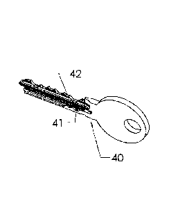
this construction, the
torque to be transferred to the lock unit, by rotating the key plug by means
of an inserted key, will
be effected by means of a single prong, situated on the opposite side of the
key plug.
[0008]
Another similar prior art document is the published US patent application US
2002/0056301 Al (Theriault), where the cylinder lock core includes two side
bars, one on each
CPST Doc: 390726.1
Date recue / Date received 2021-11-22
2
lateral side of the keyway, and also a locking segment which is movable
relative to the side bar and
the lock shell in response to the insertion of a key blade having a uniquely
configured camming
projection. In this prior art embodiment, the side bars extend along
substantially the whole length
of the key plug.
OBJECT OF THE INVENTION
[0009] There
is always a need for further improvement, and the main object of the
present invention is to further increase the security and provide a cylinder
lock unit with a high
security side locking mechanism which is very difficult to manipulate so as to
open the lock without
using a properly cut key and which will also permit the key plug to possibly
accommodate an extra
lock component in the back region of the key plug, e.g. a part of a torque
transferring connection, a
blocking mechanism for blocking full insertion of a key blade which is not
correctly cut, or an elec-
tronic component which facilitates the functioning of the lock core being
mounted in a housing.
SUMMARY OF THE INVENTION
[0010] Actually, the
present invention is a further development of an invention for
which a US application and an international patent application
(PCT/EP2018/062713), have already
been filed, but these pending patent applications have not yet been published
as of the filing date
of the present application. The present invention is different from the one
disclosed in the earlier
applications, the novelty being that the "shell" of the lock unit (with the
terminology used in the
earlier applications) is integrated with or is permanently retained in the
housing of the lock unit, and
there is no division into an external housing and an internal, exchangeable
lock "core". Rather, the
housing and general structure is more like a lock unit as disclosed in the US
patent specification
8,720,241 (Widen), the housing being divided into an upper part with locking
pins and a lower part
with a bore accommodating a rotatable key plug. Another different
distinguishing feature of the
present invention is that the key plug has a back part where a respective side
portion of the
key plug, at a lateral side of the keyway, is either massive or contains at
least one additional
lock component, such as a part of a torque transferring connection (e.g. a
screw being en-
gaged with a threaded bore in the side portion), a blocking device preventing
a full insertion
of an incorrectly cut key into the keyway, or an electronic device for
assisting in the proper
functioning of the cylinder lock unit.
[0011] The
object stated above is achieved by providing a cylinder lock unit of the kind
described herein.
CPST Doc: 390726.1
Date recue / Date received 2021-11-22
3
[0012] In
contrast to some prior art structures, there is a direct contact between the
side locking tumblers and an associated key, without the intermediary of any
other moving part. In
this way, the structure will be relatively simple and reliable. Because of the
different code positions
for each side locking tumbler in the row, the number of possible combinations
will be very large, so
the security will be high. Even so, there is room for possibly accommodating
an extra lock compo-
nent, separate from the coded locking pins and tumblers, on each lateral side
of the keyway in the
relatively long back region of the key plug.
[0013] On
the other hand, the relatively short front region of key plug is rather
compact
and preferably substantially solid, except for the keyway, the cavities for
the locking pins and any
recesses and holes for accommodating the side locking mechanism or mechanisms.
[0014]
Thanks to the above-defined structure of the cylinder lock core, with a
relatively
short front region of the rotatable key plug, having a maximum length or 50%
of the total length of
the key plug, there will be a secure and distinct interaction between the key
plug and the surround-
ing housing, by way of the side locking mechanism which is located in its
entirety within the front
75 region of
the key plug, and yet leaving room for possibly accommodating an extra lock
component
in the back region of the rotatable key plug.
[0015]
Preferably, there is one relatively short (in the axial direction) side
locking mech-
anism on each side of the keyway in the front region of the key plug. Then, it
is possible to accom-
modate at least four (two or more on each side) independently movable locking
tumblers being
separate and independent from the conventional central locking pins. However,
it is also possible
to arrange only one side locking mechanism arranged on one lateral side of the
keyway.
[0016] The
length of the front region of the key plug, where the at least one side
locking
mechanism is located in its entirety, is thus rather short, e.g. 50%, about
40% or about 30% of the
total length of the key plug. Nevertheless, thanks to the compact structure of
the side locking mech-
anism, it can still provide a very large number of code combinations and a
high security for the cyl-
inder lock core.
[0017] It
has turned out that each longitudinal row of side locking tumblers, on one or
both lateral sides of the key plug, may comprise at least two and preferably
at least three (or even
more) side locking tumblers.
[0018] Preferably, the
additional lock component possibly accommodated in the back
region of the key plug, on each lateral side of the keyway, may form a part of
the torque transferring
connection, e.g. a threaded hole for engaging with a fastening screw being
connected to a door
locking mechanism in the associated lock unit, or a blocking device for
preventing the full insertion
CPST Doc: 390726.1
Date recue / Date received 2021-11-22
4
of an incorrectly cut key blade, or an electronic device for assisting in the
proper functioning of the
cylinder lock core in relation to the lock unit.
[0019] Also, according to the present invention, the cylinder lock
unit as defined above
may be provided in combination with a key for unlocking the cylinder lock
unit, the key comprising
a grip portion and a key blade, wherein
[0020] said key blade, on at least one side thereof, has a wave-
like side code pattern
consisting of a row of at least two side code portions being substantially
confined to the longitudinal
half of the key blade located closest to said grip portion, said wave-like
code pattern adjoining to a
straight profile groove extending towards the free end of the key blade.
[0021] Moreover, the present invention relates to a key, as such, for
unlocking a cyl-
inder lock unit of the kind referred to above, the key blade, on at least one
side thereof, having a
wave-like side code pattern consisting of a row of at least two side code
portions being substantially
confined to the longitudinal half of the key blade located closest to the grip
portion, said wave-like
side code pattern adjoining to a straight profile groove extending to the free
end of the key blade,
75 and the wave-like side code pattern being preferably located at a ridge
portion of an undercut pro-
file groove in at least one side surface of the key blade.
[0022] Further advantageous features of the present invention are
stated in the ap-
pended claims and will also appear from the detailed description of some
preferred embodiments,
reference being made to the attached drawings.
BRIEF DESCRIPTION OF THE DRAWINGS
[0023] Fig. 1 shows, in a perspective view, a lock unit according
to the present inven-
tion, and a key which is insertable into a key plug forming part of the lock
unit;
[0024] Fig. 2a shows an exploded view of the various parts of the
lock unit of fig. 1;
[0025] Fig. 2b shows the key of fig. 1, in a perspective view from the
other side;
[0026] Fig. 3c shows a longitudinal section through the lock unit
of fig. 1 with the key
being inserted into the key plug;
[0027] Fig. 4 shows a cross-section through the lock unit of fig. 1
and 2a, at the location
of a side locking tumbler;
[0028] Figs. 5a, 5b, 5c and 5d show the key plug of fig. 2a, in views from
below, from
the front end, from above and in a longitudinal section, respectively;
[0029] Fig. 6 shows a key plug of a similar embodiment as in Fig.
5d, but with four side
locking tumbler holes in a row;
CPST Doc: 390726.1
Date recue / Date received 2021-11-22
5
[0030] Figs.
7a, 7b, 7c and 7d show a key plug of a second embodiment which is similar
to the one of Figs. 5a to 5d, but with a shorter side locking mechanism on
each side of the key plug,
with two locking tumblers in each side locking mechanism;
[0031] Figs.
8a, 8b, 8c and 8d show a key plug of a modified embodiment which is sim-
ilar to the one of Figs. 5a to 5d, but with only six locking pins (instead of
seven locking pins in the
previous embodiments) and two side locking tumblers on each side of the key
plug;
[0032] Figs.
9a, 9b, 9c, 9d, 9e, 9f, 9g and 9h show, in various views, a third embodiment
having a side locking mechanism provided with a side bar which cooperates with
two side locking
tumblers on one lateral side of the keyway;
[0033] Fig. 10 shows a
modified embodiment of the side locking mechanism having a
side bar interacting with side locking tumblers which are movable up and down
and also rotatable
around their own axes;
[0034] Fig.
11 shows another modified embodiment where the side locking tumblers
are each provided with a longitudinally displaced finger;
[0035] Figs. 12a, 12b,
12c and 12d show, in views corresponding to Figs. 5a, 5b, 5c and
5d, respectively, an embodiment having three side locking tumblers interacting
with a side bar, on
one lateral side of the keyway;
[0036] Figs.
13a and 13b show, in perspective and sectional views, a fourth embodi-
ment with two side bars, one on each lateral side of the keyway of the key
plug;
[0037] Fig. 13c shows
a modified embodiment with a massive back region of the key
plug, and two short side bars in the front region of the key plug; and
[0038] Figs.
14a and 14b show a modified embodiment of the key with two different
side code patterns on each side of the key blade.
DETAILED DESCRIPTION OF PREFERRED EMBODIMENTS
[0039] A
first embodiment of the lock unit 100 of the invention is shown in Figs. 1,
2a,
2b, 3, 4, 5a, 5b, 5c and 5d, including a cylindrical housing 200 with a
rotatable key plug 300, and an
associated key 40.
[0040] The
cylindrical housing 200 has a threaded rear end portion and a slightly coni-
cal front end flange.
[0041] The
torque transferring mechanism may be formed differently, as is known per
se by those skilled in the art.
CPST Doc: 390726.1
Date recue / Date received 2021-11-22
6
[0042] The
lock unit 100 is normally permanently mounted in a door or the like in order
to cooperate with a door locking mechanism, as is well known per se. The
cylindrical housing 200
includes an upper, solid part 220 and a lower part 240 forming a cylindrical
bore accommodating a
rotatable key plug 300.
[0043] The rotatable
key plug 300 is formed in one piece and is adapted to transfer a
torque to a locking mechanism when the plug Is rotated. In this embodiment, as
will be seen in fig.
2a, this is achieved by a torque transferring connection including a cam
member 151 which is se-
cured to the key plug 300 by means of two fastening screws 152a, 152b, which
engage with threaded
holes in a back region L1 of the key plug, on each side of a keyway 320.
[0044] It should be
pointed out that the torque transferring connection may be formed
by other mechanical means, e.g. with a recess in the rear end of the key plug
being coupled to a
mating member forming a part of a locking mechanism in a door or some other
object to be locked
in a closed position. If so, the back region L1 of the key plug may be used
for some other lock com-
ponent, as indicated above. It is also possible to leave the back region of
the key plug as a massive
75 material portion, on each lateral side of the key way, as indicated in
fig. 13c.
[0045] The
upper, solid part 220 of the housing 200 (see Fig. 2a), has a central row of
parallel cavities or holes 221a, 221b, 221c, 221d, 221e, 221f and 221g, the
number of cavities being
seven in this particular embodiment. As will be shown below, other normal
embodiments are pro-
vided with six such cavities in a central row. At the upper side, a
longitudinal cover plate 222 will
normally cover the holes 221a, etc. from above and keep a corresponding number
of upper and
lower locking pins 231a, etc., 232a, etc. and associated springs 235a, etc. in
place.
[0046] The
key plug can also be seen in Figs. 3,4, 5a, 5b, 5c and 5d. The outer diameter
of the cylindrical key plug is slightly smaller than the inside diameter of
the bore in the lower part
240 of the housing, so that the key plug can rotate in relation to the housing
200. However, the
possible rotary motion of the key plug is dependent on the positions of lower
locking pins 231a,
231b, 231c, 231d, 231e, 231f, 231g shown in Fig. 2a and being movable in
corresponding vertical
cavities or holes 331a, 331b, 331c, 331d, 331e, 331f, 331g arranged in a
central longitudinal row in
the upper part of the key plug 300. These vertical holes 331a, etc. are
located above the central
keyway 320. The lower locking pins 231a etc. are held in place by associated
top or upper pins 232a,
232b, 232c, 232d, 232e, 332f, 232g (collectively denoted 232a - 232g in Fig.
2a) and corresponding
helical springs 235a, 235b, 235c, 235d, 235e, 235f, 235g (collectively denoted
235a-235g in Fig. 2a).
[0047]
Accordingly, In the key plug 300, the central row of corresponding cavities
331a,
331b, 331c, 331d, 331e, 331f, 331g will accommodate the lower locking pins
231a, 231b, 231c, 231d,
231e, 231f, 231g.
CPST Doc: 390726.1
Date recue / Date received 2021-11-22
7
[0048] In
the normal operation of the cylinder lock, a correctly cut key 40 will operate
the cylinder lock unit so as to rotate the key plug 300 and turn the rear cam
151.
[0049] In
accordance with the present invention, the back region (L1 in fig. 5d) of the
key plug 300 is relatively long, viz, at least 50% of the total length (L1
+FR1) of the key plug, measured
from the back end up to a the front end flange 310, whereas the front region
(FR1 in fig. 5 d) of the
key plug is relatively short, viz, at most 50 % of the full length thereof.
Yet, the front region FR1
should be long enough to accommodate a side locking mechanism including a
longitudinal row of at
least two side locking tumblers.
[0050] As
indicated above, the back region (L1) of the key plug serves to accommodate
the rear part of the central row of holes 331a ¨ 331g above the keyway 320,
possibly also an addi-
tional lock component, which may be a part of the torque transferring
connection, such as the fas-
tening screws 152b on either side of the keyway, or a blocking mechanism which
will prevent the
full insertion of an incorrectly cut key blade, or an electronic component
which will facilitate or assist
in the proper functioning of the lock unit. Thus, the additional lock
component is not a coded locking
75 pin or
tumbler serving primarily to permit rotation of the key plug only when being
positioned by a
properly cut key blade upon full insertion thereof into the keyway.
[0051]
Importantly, the key plug 300 is provided with a side locking mechanism which
is located on at least one lateral side of the keyway 320 and which is
confined entirely within the
front region FR1 located longitudinally in front of the back region L1.
Preferably, this front region
FR1 is substantially solid, except for the keyway, the cavities for the lower
locking pins and any re-
cesses and holes for accommodating the side locking mechanism itself.
According to the invention,
the side locking mechanism comprises at least two independently movable side
locking tumblers
providing a high security mechanism with at least three different code
positions for each locking
tumbler and a plurality of different code combinations for the side locking
tumblers.
[0052] In the
embodiment described above, see Fig. 3, 4, 5a, 5b, Sc, and 5d, the side
locking mechanism includes three coded side locking tumblers 351a, 351b, 351c
(figs. 2a and 5a)
which are arranged in a row at one side of the keyway 320 of the key plug 300,
in the solid front
region thereof. The three locking tumblers are located entirely within this
front region and also ra-
dially inside lower part 240 of the housing. This location of the side locking
mechanism 351a, 351b,
351c has the advantage that it will interact mainly with the lower part 240 of
the housing in associ-
ated recesses or holes 242 (fig. 2a and fig. 4), next to the front end flange
310 of the key plug 300.
Other embodiments are possible, as will be described below.
[0053] The
three side locking tumblers 351a, 351b, 351c are biased by springs 361a,
361b, 361c (collectively denoted 361a ¨ 361c in Fig. 2a) in associated
vertical cavities or holes 371a,
CPST Doc: 390726.1
Date recue / Date received 2021-11-22
8
371b, 371c (collectively denoted 371a-371c in Fig. 4a) at some lateral
distance from the keyway 320
so as to project into the keyway with a projecting finger (visible in Fig. 5b)
which will cooperate with
a wave-like side code pattern 41 on the key blade of the associated key 40
(fig. 2b). When the key
40 is inserted into the keyway 320, the locking tumblers 351a, etc. will move
up and down in re-
sponse to their contact with the side code pattern 41. The lower ends of the
coded side locking
tumblers 351a, etc. will then interact with the associated recesses or holes
242 in the lower part 240
of the housing 200. At the same time, a number of V-shaped bittings at the
upper edge portion 42
of the key 40 will interact with the central row of locking pins 231a, etc.
Only when all of the lower
and upper locking pins 231a, etc. and 232a, etc. and the three side locking
tumblers 351a, etc. are
correctly positioned within the circumference of the key plug 300, will it be
possible to turn the key
40 so as to rotate the key plug 300 and unlock the cylinder lock unit.
[0054] It is
important that the side tumblers 351a, etc. are movable independently of
the central locking pins 231a, etc. Thus, if the cylinder lock is manipulated
with a so called "bumping"
technique, it may be possible to position all the locking pins 231a, but it
will be much more difficult
to simultaneously manipulate also the coded side locking tumblers 351a, etc.
into their respective
coded positions. Thus, the side locking mechanism 351 will provide a high
security for the cylinder
lock core.
[0055] The
interaction between the side locking tumbler 351b of the key plug 300 and
the surrounding lower part 240 of the housing is illustrated further in Figure
4 showing the embod-
iment of Fig. 2a in cross-section.
[0056] In
Fig. 4, the side locking tumbler 351b is located in its totally retracted
position
within the key plug, where both of its ends are located at the shear line
between the key plug 300
and the surrounding lower part 240 of the housing, and the central pin 231f is
also located with its
upper end being located flush with the shear line. In this position, the key
plug can be rotated or
turned, provided that all other central pins and coded side locking tumblers
are also confined within
the key plug.
[0057] In
Figs. 5a, 5b, Sc, 5d, the basic (first) embodiment is shown, with the three
side
locking tumblers 351a, 351b, 351c in a longitudinal row in associated holes
371a, 371b, 371c on one
lateral side of the keyway 320, as described above. Since each side locking
tumbler 351a, 351b, 351c
has three possible codes, in this example, the total number of codes for the
side locking mechanism
will be 3x3x3 = 27 in this case.
[0058] In a
modified version of the first embodiment, as shown in Fig. 6, there are four
side locking tumblers in a longitudinal row, in associated holes 371a, 371b,
371c, 371d. The back
region L1 and the front region FR1 of the key plug are just as long as in the
previous embodiment.
CPST Doc: 390726.1
Date recue / Date received 2021-11-22
9
[0059] In a
second embodiment, illustrated in Figs. 7a, 7b, 7c and 7d, the structure is
similar to the first embodiment (all the reference numerals starting with the
digit 4 instead of 3),
but here there is a row of coded side locking tumblers on each side of the
keyway 420, each such
row consisting of two independently movable side locking tumblers 451a, 451b
and 461a, 461b,
respectively. Each side locking tumbler will interact with the surrounding
lower part of the housing
in the same way as shown in Fig. 4. Thus, there are four side locking tumblers
which are movable
independently of each other, each in at least three elevational positions. So,
the number of possible
code combinations will be even higher in this embodiment (at least 3 x 3 x 3x
3 = 81).
[0060] The
back region L2 of the key plug 400 is somewhat longer in this second em-
bodiment, and the front region FR2 is shorter (the total length L2 + FR2 being
the same as in Fig. 5d.
[0061] In a
modified version of the second embodiment, shown in Figs. 8a, 8b, 8c and
8d, the structure is exactly the same as in the one shown in Figs. 7a, etc.,
except that the number of
central locking pins 231a', ...231f (Fig. 8c) in the key plug 400' is six
rather than seven and the total
length of the key plug is a little shorter. Still, the length of the back
region L2' is slightly more than
75 half of the length of the key plug.
[0062] In a
third embodiment, shown in Figs. 9a, 9b, 9c, 9d, 9e, 9f, 9g, 9h and Fig. 10,
the number of central locking pins is again seven, like in most of the
previous embodiments, but the
side locking mechanism is different, with only two side locking tumblers on
one side of the key plug
500 only, these two side locking tumblers 551a, 551b cooperating with a
relatively short side bar
580 (Fig. 9d). Such a side locking mechanism with a side bar is known per se,
but not in the context
of cylinder lock unit having a key plug with a back region being reserved for
a possible extra lock
component, e.g. two relatively long fastening screws for securing a cam member
or the like in the
back region of the key plug. The side bar 580 is normally held in a
longitudinal recess or groove 243
(see Fig. 9a) by a spring 581 (see Fig. 9d), located between the two side
locking tumblers to save
longitudinal space, in a position where it projects sideways outside the
contour of the key plug 500.
In this position, the side bar will register with the corresponding groove 243
in the lower part 240
of the housing 200 and thereby effectively lock the key plug against rotation.
However, when the
side locking tumblers 551a and 551b are positioned in certain vertical
positions, by means of the
properly cut key 40, the side bar 580 can be moved sideways, against the
action of the spring 581,
into a retracted position where it is no longer seated in the groove 243.
Thus, by turning the key 40,
the side bar 580 will be retracted and permit rotation of the key plug 500.
Then, a projecting lug
580a of the sidebar will find its way into a coded recess 555 in the
cylindrical surface of the side
locking tumbler 551b. This interaction will be seen clearly in the enlarged
view in Fig. 9c, which also
shows how the transverse finger 554 of the side locking tumbler 551b will be
lifted to the right
CPST Doc: 390726.1
Date recue / Date received 2021-11-22
10
position by the side code pattern on the key 40. By way of the side bar, the
side locking mechanism
will provide a high degree of security, since it is difficult to manipulate
the side locking tumblers
551a, 551b so as to release the lock. In this embodiment, with only two side
locking tumblers in a
row, the back region of the key plug 500 may have a greater length L3, as
shown in Fig. 9h, leaving
only a relatively short front region FR3.
[0063] As
shown in Figs. 10 and 11, each side locking tumbler can interact in different
ways with the side bar, either by way of rotating along its axis or being non-
rotatable and having a
longitudinally displaced finger. In Fig. 10, the side locking tumbler 651b can
rotate between two
rotary end positions, as indicated by the arrow R. A material portion 655,
between two adjacent
recesses 656,657 in the cylindrical surface of the side locking tumbler can
fit into a corresponding
slot 680a in the side bar 680. With two or three rotary positions and three or
more levels of the
coded recesses 656, 657, the code combinations for each locking tumbler 651b
will be 6 or higher.
In this case, the code pattern at the side of the key must be configured to
accommodate for two or
three different pivotal positions of the transverse finger 654.
[0064] Similarly, in
Fig. 11, the transverse finger 754 of the side locking tumbler 751b,
is longitudinally displaced (along the longitudinal axis of the keyway of the
key plug) into one of
three coded positions. Accordingly, with several possible levels of the
recesses 755 at the cylindrical
surface of the tumbler, there will also be a large number of code combinations
for each side locking
tumbler, e.g. 9 or higher.
[0065] In a modified
version of the third embodiment, shown in Figs. 12a, 12b, 12c,
12d, there are three side locking tumblers 951a, 951b, 951c (on one side of
the keyway 920 of the
key plug 900) which interact with a somewhat longer side bar 980, biased by
springs 981.
[0066] In a
fourth embodiment, shown in Figs. 13c, there are two relatively short side
locking mechanisms, one on each side of the keyway 820 and each having a side
bar 880, adjacent
to the front end flange of the key plug 800. This is a favorable embodiment
with a very high number
of code combinations and yet a very compact structure confined within a rather
small part (less than
20%) of the total length of the key plug. The back region has a relatively
long length L2, being massive
except for the rear part of the central row of holes or cavities, and the
front region FR2 is relatively
short, but if necessary, the front region of the key plug may be just as short
as in the embodiment
shown in Fig. 9h (FR3).
[0067]
Finally, a fifth embodiment is shown in Figs. 13a and 13b where the key plug
800', in its solid front end region FR1, is provided, on each lateral side of
the keyway, with a row of
four side locking tumblers 851a', 851b', 851c', 851d' cooperating with an
associated side bar 880'.
CPST Doc: 390726.1
Date recue / Date received 2021-11-22
11
Here, since the side locking mechanisms are arranged on both lateral sides of
the keyway, each with
four side locking tumblers in a row, the result will be a very large number of
code combinations.
[0068] Figs.
14b shows also the housing for the fifth embodiment. It is similar to the
one shown in Fig. 2a, although it is adapted to the arrangement with two side
bars 880'. Here, each
side bar 880' is seated, in its locking position, in a respective groove 243"
in the lower part of the
housing.
[0069] The
side bars shown in Figs. 9a to 9h, 10, 11, 12d, 13a, 13b, 13c are very favor-
able in that the springs (e.g. 581 in Fig. 9d), which push the side bar
radially outwardly, are each
located between a pair of side locking tumblers, so that the end of the side
bar can be positioned
very close to the front end of the key plug, thereby saving space. Preferably,
one of the springs
should be positioned between the two neighboring side locking tumblers being
located closest to
the front end flange of the key plug and cooperate with the side bar. When
there are only two side
locking tumblers cooperating with the side bar, as shown in figs. 9h and 13c,
there is only a single
spring, making the side locking mechanism very compact.
75 [0070] Also, in
all embodiments, the hole (e.g. 371c) for the side locking tumbler (e.g.
351c) being located closest to the front end of the key plug is located closer
to the front end flange
than all the central holes (e.g. 331a ¨ 331g), whereby the space for the side
locking mechanism is
utilized efficiently, and there is consequently room for at least two and
possibly three or four side
locking tumblers in a row in the front region FR1, FR2, FR3 which is at the
most half of the total
length of the key plug and possibly much shorter.
[0071] The
associated key 40, having a wave-like side code pattern 41 (see Fig. 4b) with
code portions interacting with the side locking tumblers, will have the entire
side code pattern 41
located substantially within the half of the key blade being located closest
to the grip portion of the
key. Furthermore, the side code portion of this pattern 41 located closest to
the grip portion will be
located closer to the grip portion than all the V-shaped bittings 42 on the
edge of the key, the latter
bittings interacting with the central row of locking pins of the cylinder
lock. In this way, these keys
40 will be distinguished from all prior art keys.
[0100] The
key, see fig. 2b, may alternatively have a wave-like side code pattern 41 on
only one side of the key blade. The other side may be just flat or provided
with some other code
pattern or configuration.
[0101] An
example of different code patterns 141 and 141' on the two sides of the key
blade is shown in figs. 14a and fig. 14b.
[0102] In
fig. 14a, the side code pattern 141' on one side of the key blade is formed by
two parallel upper and lower wall surfaces of a profile groove having a first
part with two side code
CPST Doc: 390726.1
Date recue / Date received 2021-11-22
12
portions confined to the longitudinal half of the key blade, located closest
to the grip portion of the
key, and a second part forming a straight profile groove without any side code
portions.
[0103] The
other side of the key, shown in fig. 14b, also has a first part with side code
portions confined to the longitudinal half of the key blade located closest to
the grip portion, and a
second part forming a straight profile groove without any side code portions.
On this side of the key
blade, however, the profile groove is undercut and provided with a ridge
portion where the side
code portions are located. The upper wall surface of the profile groove is
straight all the way, so the
side code tumblers of the lock unit interacting with the lower wave-like
guiding surface of the profile
groove must be biased downwardly, e.g. by springs, in order to follow the wave-
like guiding surface.
[0104] As is known per
se in this kind of technology, the side code portions may be
formed by concavities in the wave-like guiding surface of the undercut profile
groove.
[0105] In
principle, it is possible to use a key which is only provided with a side code
pattern, on one or both sides of the key blade, and no bittings at the upper
edge of the key blade. If
so, a local lock smith can form an edge code on such a key at a later stage,
if desired.
[0106] As is also
known in this kind of technology, the V-shaped bittings of the upper
edge code pattern, if any, may be skew cut at different angles.
[0107] Also,
it is of course possible to provide a key where the wave-like side code pat-
tern is selected from a group of possible code positions, the possible code
position including, at
different vertical levels:
[0108] ¨ a central
position, corresponding to the position of an axis of a side locking
tumbler of the associated cylinder lock unit, when the key is fully inserted
in the keyway,
[0109] ¨ a
forwardly displaced position being displaced longitudinally at an incremen-
tal distance from the central position towards the free end of the key blade,
[0110] ¨ a
rearwardly displaced position being displaced longitudinally at an incremen-
tal distance from the central position towards the grip portion of the key,
[0111] ¨
said central position, said forwardly displaced position and said rearwardly
displaced position each corresponding to a particular position of a transverse
finger, such as the
finger 654 or the finger 754 described above, on said side locking tumbler of
the associated lock unit
when the key is fully inserted into the keyway of the rotatable key plug.
CPST Doc: 390726.1
Date recue / Date received 2021-11-22