Language selection

Search

Patent 3120078 Summary

Third-party information liability

Some of the information on this Web page has been provided by external sources. The Government of Canada is not responsible for the accuracy, reliability or currency of the information supplied by external sources. Users wishing to rely upon this information should consult directly with the source of the information. Content provided by external sources is not subject to official languages, privacy and accessibility requirements.

Claims and Abstract availability

Any discrepancies in the text and image of the Claims and Abstract are due to differing posting times. Text of the Claims and Abstract are posted:

  • At the time the application is open to public inspection;
  • At the time of issue of the patent (grant).
(12) Patent Application: (11) CA 3120078
(54) English Title: ROADWAY BARRIER APPARATUS
(54) French Title: APPAREIL DU TYPE BARRIERE ROUTIERE
Status: Examination
Bibliographic Data
(51) International Patent Classification (IPC):
  • E05D 11/10 (2006.01)
(72) Inventors :
  • LIM, JASON T. (United States of America)
  • THOMPSON, JEFFREY M. (United States of America)
  • BOSTON, RICHARD (United States of America)
(73) Owners :
  • LINDSAY TRANSPORTATION SOLUTIONS, LLC
(71) Applicants :
  • LINDSAY TRANSPORTATION SOLUTIONS, LLC (United States of America)
(74) Agent: ROBIC AGENCE PI S.E.C./ROBIC IP AGENCY LP
(74) Associate agent:
(45) Issued:
(86) PCT Filing Date: 2019-10-22
(87) Open to Public Inspection: 2020-05-22
Examination requested: 2022-09-29
Availability of licence: N/A
Dedicated to the Public: N/A
(25) Language of filing: English

Patent Cooperation Treaty (PCT): Yes
(86) PCT Filing Number: PCT/US2019/057334
(87) International Publication Number: US2019057334
(85) National Entry: 2021-05-14

(30) Application Priority Data:
Application No. Country/Territory Date
16/190,498 (United States of America) 2018-11-14

Abstracts

English Abstract

Roadway barrier apparatus including roadway barrier modules disposed end to end and pivotally connected together by a pivot pin positioned in aligned apertures of connector brackets at the ends of the modules, the pivot pin having a groove and a spring biased hinge pusher member positionable in the groove to limit upward movement of the pivot pin.


French Abstract

La présente invention concerne un appareil du type barrière routière comprenant des modules de barrière routière disposés bout à bout et raccordés pivotants les uns aux autres par une broche de pivot positionnée dans des ouvertures alignées de supports de raccord au niveau des extrémités des modules, la broche de pivot présentant une rainure et un élément poussoir de charnière sollicité par ressort pouvant être positionné dans la rainure pour limiter un mouvement vers le haut de la broche de pivot.

Claims

Note: Claims are shown in the official language in which they were submitted.

6
The Invention Claimed Is:
1. Roadway
barrier apparatus comprising, in
combination:
a first roadway barrier module having a double-
ended first module body and upper and lower first module
connector brackets extending from each end thereof, said
upper and lower first module connector brackets spaced a
fixed vertical distance from one another and defining
aligned first module bracket apertures;
a second roadway barrier module having a double-
ended second module body and upper and lower second module
connector brackets extending from each end thereof, said
upper and lower second module connector brackets spaced
from one another and defining aligned second module bracket
apertures, the first module body and the second module body
being disposed with opposed ends thereof spaced from one
another and the upper first and second module connector
brackets thereof in overlapping relationship and the lower
first and second module connector brackets in overlapping
relationship with the first module bracket apertures and
the second module bracket apertures aligned;
a spring biased hinge pusher member slidably
connected to the first module body and extending toward the
second module body; and
a pivot pin positioned between said first module
body and said second module body in said aligned apertures
of said first and second module body connector brackets and
extending through said upper and lower first and second
module connector brackets, said pivot pin having a
circumferentially extending groove, said pivot pin
including a pivot pin top portion above the topmost upper
module connector bracket and= said spring biased hinge
pusher member positioned in said circumferentially
extending groove to limit upward movement of said pivot pin
and prevent disengagement of said pivot pin from said
overlapping upper and lower connector brackets due to
ratcheting effect caused by relative motion between the

7
first and second roadway barrier modules.
2. The roadway barrier apparatus of Claim 1
wherein said pivot pin groove is defined by upper and lower
circular chamfered surfaces.
3. The roadway barrier apparatus of Claim 2
wherein said hinge pusher member and said spring are
positioned in a guide structure disposed in a cavity of
said first module body.
4. The roadway barrier apparatus of Claim 3
wherein said pusher member has a pin contact surface
engaging said pin between said upper and lower circular
chamfered surfaces.
5. The roadway barrier apparatus according to
Claim 3 including a guide projection attached to the hinge
pusher member slidable in a slot in the guide structure.

Description

Note: Descriptions are shown in the official language in which they were submitted.


CA 03120078 2021-05-14
WO 2020/101840
PCT/US2019/057334
1
ROADWAY BARRIER APPARATUS
TECHNICAL FIELD
This invention relates to roadway barrier
apparatus and more particularly to an improved apparatus
incorporating pivotally connected roadway barrier modules.
BACKGROUND OF THE INVENTION
Pivotally connected roadway barrier modules are
well known and interconnection between the modules is
commonly accomplished by use of connector pins hingedly
connecting the roadway barrier modules.
Under certain conditions a connector pin of
conventional type is subject to a ratcheting load that can
push the pin up and out of position during pickup and
placement of the barrier. It is known to put a retaining
clip on the pin but it is cumbersome and difficult to apply
and remove. Further, such an approach has challenges with
forces. In some cases special tools are required to place
or remove the connector pin.
The following patent documents disclose
arrangements which are believed to be representative of the
current state of the art in this field: U.S. Patent No.
9,068,382, issued June 30, 2015, U.S. Patent No. 8,939,675,
issued January 27, 2015, U.S. Patent No. 7,708,492, issued
May 4, 2010, U.S. Patent No. 6,837,647, issued January 4,
2005, U.S. Patent No. 5,412842, issued May 9, 1995, U.S.
Patent No. 5,040,268, issued August 20, 1991, U.S. Patent
No. 4,828,425, issued May 9, 1989, U.S. Patent No.
4,806,044, issued February 21, 1989, U.S. Patent No.
3,874,029, issued April 1, 1975, U.S. Patent No. 7,393,154,
issued July 1, 2008, U.S. Patent No. 6,632,044, issued
October 14, 2003, and French Patent No. FR2826024, dated
October 29, 2004.
BRIEF SUMMARY OF THE INVENTION
The roadway barrier apparatus of this invention
includes a first roadway barrier module having a double-

CA 03120078 2021-05-14
WO 2020/101840 PCT/US2019/057334
2
ended first module body and upper and lower first module
connector brackets extending from each end thereof. The
upper and lower first module connector brackets are spaced
a fixed vertical distance from one another and define
aligned first module bracket apertures.
The apparatus also includes a second roadway
barrier module having a double-ended second module body and
upper and lower second module connector brackets extending
from each end thereof. The upper and lower second module
connector brackets are spaced a fixed vertical distance
from one another and define aligned second module bracket
apertures.
The first module body and the second module body
are disposed with opposed ends thereof spaced from one
another. The upper first and second module connector
brackets thereof are in overlapping relationship and the
lower first and second module connector brackets are in
overlapping relationship with the first module bracket
apertures and the second module bracket apertures being
aligned.
A spring biased hinge pusher member is slidably
connected to the first module body and extends toward the
second module body.
A pivot pin is positioned between the first
module body and the second module body in the aligned
apertures of the first and second module bar connector
brackets and extends through said upper and lower first and
second module connector brackets..
The pivot pin has a circumferentially extending
groove. The pivot pin includes a pivot pin top portion
above the topmost upper module connector bracket and the
spring biased hinge pusher member is positioned in the
circumferentially extending groove to limit upward movement
of the pivot pin and prevent disengagement of said pivot
'pin from the overlapping upper and lower connector brackets
due to ratcheting effect caused by relative motion between
the first and second roadway barrier modules.

CA 03120078 2021-05-14
WO 2020/101840
PCT/US2019/057334
3
Other features, advantages and objects of the
present invention will become apparent with reference to
the following description and accompanying drawings.
BRIEF DESCRIPTION OF DRAWINGS
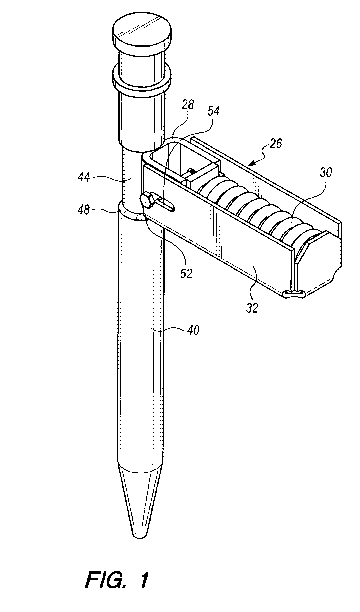
Fig. 1 is a perspective view of an assembly
including a pivot pin constructed in accordance with the
teachings of the present invention in operative association
with a spring biased hinge pusher member positioned in a
guide structure;
Fig. 2 shows two roadway barrier modules
connected by the pivot pin of the present invention
extending through connector brackets of the modules, the
assembly illustrated in Fig. 1 located in a cavity of the
roadway barrier modules;
Fig. 3 is a front, elevational view illustrating
one of the roadway barrier modules having the pivot pin
positioned in and extending through the upper and lower
connector brackets thereof;
Fig. 4 is an enlarged, elevational view of the
drawing portion indicated in Fig. 2 by reference numeral 4;
and
Fig. 5 is an enlarged, perspective view of the
assembly hinge pusher member and spring, the guide
structure shown in dash lines.
DETAILED DESCRIPTION OF THE INVENTION
The present invention is directed to roadway
barrier apparatus comprising a plurality of pivotally
connected roadway barrier modules, the roadway barrier
modules interconnected by structure of the present
invention. Two such roadway barrier modules 10 and 12 are
shown, but it is of course to be understood that they
typically are utilized in a longer string of roadway
barrier modules.
The illustrated arrangement includes roadway
barrier modules 10, 12 of like construction. Each roadway
barrier module has a double-ended module body 14. In the
illustrated embodiment the roadway barrier module bodies

CA 03120078 2021-05-14
WO 2020/101840
PCT/US2019/057334
4
are of steel reinforced concrete but the principles of this
invention apply to other module body constructions. Each
roadway barrier module has an elongated upper module
connector bracket 16 extending from both ends thereof.
Lower module connector brackets 18 of the barrier modules
also extend from both ends of the module body, the upper
and lower module connector brackets spaced from one another
and defining aligned module bracket apertures 20.
The module bodies 14 of the roadway barrier
modules 10, 12 are disposed with opposed ends thereof
spaced from one another and the upper first and second
module connector brackets 16, 18 thereof in overlapping
relationship. The module bracket apertures thereof are
aligned, as is conventional.
In the drawings an assembly 26 is shown
positioned in a cavity of module bodies 14. The assembly 26
includes a hinge pusher member 28, a spring 30 and a guide
structure 32 which accommodates the hinge pusher member 28
and spring 30. The pusher member 28 in the assembly in
second module 12 is urged in the direction of the module
body 14 of roadway barrier module 10.
A pivot pin 40 is positioned between the module
bodies 14 of roadway barrier modules 10, 12. The pivot pin
40 is in the aligned apertures 20 at the ends of the module
body connector brackets 16, 18 and extends through both the
overlapped upper and lower module connector brackets.
The pivot pin 40 has the circumferentially
extending groove 44 defined by upper circular chamfered
surface 46 and lower circular chamfered surface 48. The
hinge pusher member 28 is positioned in the groove 44 to
limit upward movement of the pivot pin and prevent
disengagement of the pivot pin from the overlapping upper
and lower connector brackets due to ratcheting effect
caused by relative motion between the first and second
roadway barrier modules. The pin contact surface 50 of the
hinge pusher member engages the pin between the upper and
lower chamfered surfaces. The path and placement of the

CA 03120078 2021-05-14
WO 2020/101840
PCT/US2019/057334
hinge pusher member 28 is controlled by a guide projection
52 attached to the hinge pusher member 28 and positioned in
a slot 54 of the guide structure.
The chamfered circular surfaces facilitate
removal of the pin from the module connector brackets when
desired.

Representative Drawing
A single figure which represents the drawing illustrating the invention.
Administrative Status

2024-08-01:As part of the Next Generation Patents (NGP) transition, the Canadian Patents Database (CPD) now contains a more detailed Event History, which replicates the Event Log of our new back-office solution.

Please note that "Inactive:" events refers to events no longer in use in our new back-office solution.

For a clearer understanding of the status of the application/patent presented on this page, the site Disclaimer , as well as the definitions for Patent , Event History , Maintenance Fee  and Payment History  should be consulted.

Event History

Description Date
Amendment Received - Response to Examiner's Requisition 2024-05-17
Amendment Received - Voluntary Amendment 2024-05-17
Examiner's Report 2024-03-06
Inactive: Report - No QC 2024-03-06
Letter Sent 2022-12-16
Request for Examination Received 2022-09-29
Request for Examination Requirements Determined Compliant 2022-09-29
All Requirements for Examination Determined Compliant 2022-09-29
Common Representative Appointed 2021-11-13
Inactive: Cover page published 2021-06-23
Letter sent 2021-06-10
Letter Sent 2021-06-03
Application Received - PCT 2021-06-03
Request for Priority Received 2021-06-03
Inactive: IPC assigned 2021-06-03
Inactive: First IPC assigned 2021-06-03
Priority Claim Requirements Determined Compliant 2021-06-03
National Entry Requirements Determined Compliant 2021-05-14
Application Published (Open to Public Inspection) 2020-05-22

Abandonment History

There is no abandonment history.

Maintenance Fee

The last payment was received on 2023-10-13

Note : If the full payment has not been received on or before the date indicated, a further fee may be required which may be one of the following

  • the reinstatement fee;
  • the late payment fee; or
  • additional fee to reverse deemed expiry.

Patent fees are adjusted on the 1st of January every year. The amounts above are the current amounts if received by December 31 of the current year.
Please refer to the CIPO Patent Fees web page to see all current fee amounts.

Fee History

Fee Type Anniversary Year Due Date Paid Date
Basic national fee - standard 2021-05-14 2021-05-14
Registration of a document 2021-05-14 2021-05-14
MF (application, 2nd anniv.) - standard 02 2021-10-22 2021-05-14
Request for examination - standard 2024-10-22 2022-09-29
MF (application, 3rd anniv.) - standard 03 2022-10-24 2022-10-14
MF (application, 4th anniv.) - standard 04 2023-10-23 2023-10-13
Owners on Record

Note: Records showing the ownership history in alphabetical order.

Current Owners on Record
LINDSAY TRANSPORTATION SOLUTIONS, LLC
Past Owners on Record
JASON T. LIM
JEFFREY M. THOMPSON
RICHARD BOSTON
Past Owners that do not appear in the "Owners on Record" listing will appear in other documentation within the application.
Documents

To view selected files, please enter reCAPTCHA code :


To view images, click a link in the Document Description column. To download the documents, select one or more checkboxes in the first column and then click the "Download Selected in PDF format (Zip Archive)" or the "Download Selected as Single PDF" button.

List of published and non-published patent-specific documents on the CPD .

If you have any difficulty accessing content, you can call the Client Service Centre at 1-866-997-1936 or send them an e-mail at CIPO Client Service Centre.


Document
Description 
Date
(yyyy-mm-dd) 
Number of pages   Size of Image (KB) 
Claims 2024-05-16 2 113
Description 2024-05-16 6 437
Claims 2021-05-13 2 70
Abstract 2021-05-13 1 55
Drawings 2021-05-13 3 52
Description 2021-05-13 5 198
Representative drawing 2021-05-13 1 12
Examiner requisition 2024-03-05 3 147
Amendment / response to report 2024-05-16 11 363
Courtesy - Letter Acknowledging PCT National Phase Entry 2021-06-09 1 587
Courtesy - Certificate of registration (related document(s)) 2021-06-02 1 367
Courtesy - Acknowledgement of Request for Examination 2022-12-15 1 431
National entry request 2021-05-13 13 609
Patent cooperation treaty (PCT) 2021-05-13 2 82
International search report 2021-05-13 1 48
Patent cooperation treaty (PCT) 2021-05-13 1 42
Request for examination 2022-09-28 3 88