Note: Descriptions are shown in the official language in which they were submitted.
CA 03120361 2021-05-18
WO 2020/112983
PCT/US2019/063584
Universal Plug and Play Perforating Gun Tandem
RELATED APPLICATIONS
111 This application claims priority to U.S. Provisional Application No.
62/773,044, filed
November 29, 2018.
BACKGROUND OF THE INVENTION
[2] Generally, when completing a subterranean well for the production of
fluids, minerals, or
gases from underground reservoirs, several types of tubulars are placed
downhole as part of the
drilling, exploration, and completions process. These tubulars can include
casing, tubing, pipes,
liners, and devices conveyed downhole by tubulars of various types. Each well
is unique, so
combinations of different tubulars may be lowered into a well for a multitude
of purposes.
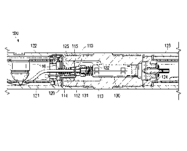
131 A subsurface or subterranean well transits one or more formations.
The formation is a body
of rock or strata that contains one or more compositions. The foimation is
treated as a continuous
body. Within the formation hydrocarbon deposits may exist. Typically, a
wellbore will be drilled
.. from a surface location, placing a hole into a formation of interest.
Completion equipment will be
put into place, including casing, tubing, and other downhole equipment as
needed. Perforating the
casing and the formation with a perforating gun is a well-known method in the
art for accessing
hydrocarbon deposits within a formation from a wellbore.
[4] Explosively perforating the formation using a shaped charge is a
widely known method for
completing an oil well. A shaped charge is a term of art for a device that
when detonated generates
a focused output, high energy output, and/or high velocity jet. This is
achieved in part by the
geometry of the explosive in conjunction with an adjacent liner. Generally, a
shaped charge
includes a metal case that contains an explosive material with a concave
shape, which has a thin
metal liner on the inner surface. Many materials are used for the liner; some
of the more common
metals include brass, copper, tungsten, and lead. When the explosive
detonates, the liner metal is
compressed into a super-heated, super pressurized jet that can penetrate
metal, concrete, and rock.
Perforating charges are typically used in groups. These groups of perforating
charges are typically
held together in an assembly called a perforating gun. Perforating guns come
in many styles, such
as strip guns, capsule guns, port plug guns, and expendable hollow carrier
guns.
1
CA 03120361 2021-05-18
WO 2020/112983
PCT/US2019/063584
151 Perforating charges are typically detonated by detonating cord in
proximity to a priming
hole at the apex of each charge case. Typically, the detonating cord
terminates proximate to the
ends of the perforating gun. In this arrangement, an initiator at one end of
the perforating gun can
detonate all of the perforating charges in the gun and continue a ballistic
transfer to the opposite
end of the gun. In this fashion, numerous perforating guns can be connected
end to end with a
single initiator detonating all of them.
[6] The detonating cord is typically detonated by an initiator triggered
by a firing head. The
firing head can be actuated in many ways, including but not limited to
electronically, hydraulically,
and mechanically.
171 Expendable hollow carrier perforating guns are typically
manufactured from standard sizes
.. of steel pipe with a box end having internal/female threads at each end.
Pin ended adapters, or
subs, having male/external threads are threaded one or both ends of the gun.
These subs can
connect perforating guns together, connect perforating guns to other tools
such as setting tools and
collar locators, and connect firing heads to perforating guns. Subs often
house electronic,
mechanical, or ballistic components used to activate or otherwise control
perforating guns and
.. other components.
[8] Perforating guns typically have a cylindrical gun body and a charge
tube, or loading tube
that holds the perforating charges. The gun body typically is composed of
metal and is cylindrical
in shape. Charge tubes can be formed as tubes, strips, or chains. The charge
tubes will contain
cutouts called charge holes to house the shaped charges.
[9] It is generally preferable to reduce the total length of any tools to
be introduced into a
wellbore. Among other potential benefits, reduced tool length reduces the
length of the lubricator
necessary to introduce the tools into a wellbore under pressure. Additionally,
reduced tool length
is also desirable to accommodate turns in a highly deviated or horizontal
well. It is also generally
preferable to reduce the tool assembly that must be performed at the well site
because the well site
is often a harsh environment with numerous distractions and demands on the
workers on site.
[10] Electric initiators are commonly used in the oil and gas industry
for initiating different
energetic devices down hole. Most commonly, 50-ohm resistor initiators are
used. Other initiators
and electronic switch configurations are common.
2
CA 03120361 2021-05-18
WO 2020/112983
PCT/US2019/063584
SUMMARY OF EXAMPLE EMBODIMENTS
[11] An example embodiment may include a tandem sub for connecting one or more
perforating
guns comprising a cylindrical body with a first end, a second end, and a
hollow inner bore, wherein
the first end is a pinned end adapted to couple to a box end of a First
perforating gun housing,
wherein the second end is a pinned end adapted to couple to a box end of a
second perforating gun
housing, wherein the inner bore is adapted to contain a plug and play
cartridge detonator assembly
that can detonate a detonating cord upon receiving an electrical command from
a wire.
[12] A variation of the example embodiment may include the tandem sub further
comprising a
cartridge detonator assembly disposed within the hollow inner bore, the
cartridge detonator further
comprising a cylindrical body housing an electrical switch and circuit board,
a distal end having a
detonator, and a contact spring for electrically coupling the detonator
assembly to a signal wire. It
may include a feed thru puck coupled to a feed thru body, disposed within the
hollow inner core.
It may include the feed thru puck having a that hole for an electrical wire.
The feed that body may
have a means for coupling the electrical wire to the puck, thereby
electrically coupling the
electrical wire with the feed that body. The contact spring may be coupled to
the feed that body.
The feed that body may have a hollow that bore adapted for containing a
booster and the detonator
adjacent to each other. The means for electrically coupling the electrical
wire with the feed thru
body may be a radial wire groove on the feed that body that an exposed end of
the wire is wrapped
around. The means for electrically coupling the electrical wire with the feed
that body may be a
tangential that hole that an exposed end of the wire is wrapped through and
around. The means for
electrically coupling the electrical wire with the feed that body may be a
metal screw that clamps
an exposed end of the wire against a metal insert that is further coupled to
the contact spring.
[13] An example embodiment further may include a perforating gun string
comprising a first
perforating gun with an uphole box end, a downhole box end, a plurality of
shaped charges
connected together with a detonating cord, and a wire disposed therein,
traveling from the uphole
end to the downhole end, a first tandem sub for connecting one or more
perforating guns coupled
to the downhole end of the first perforating gun further comprising a
cylindrical body with a first
end, a second end, and a hollow inner bore, wherein the first end is a pinned
end adapted to couple
to a box end of the first perforating gun housing, wherein the second end is a
pinned end adapted
to couple to a box end of a second perforating gun housing, and wherein the
inner bore is adapted
3
CA 03120361 2021-05-18
WO 2020/112983
PCT/US2019/063584
to contain a plug and play cartridge detonator assembly that can detonate the
detonating cord of
the first perforating gun upon receiving an electrical command from the wire.
1141 A variation of the example embodiment may include the tandem sub having a
cartridge
detonator assembly disposed within the hollow inner bore, the cartridge
detonator further
comprising a cylindrical body housing, an electrical switch and circuit board,
a distal end having
a detonator, and a contact spring for electrically coupling the detonator
assembly to a signal wire.
It may include a feed thru puck coupled to a feed thru body, disposed within
the hollow inner core.
The feed thru puck may have a thru hole for an electrical wire. The feed thru
body may have a
means for coupling the electrical wire to the puck, thereby electrically
coupling the electrical wire
with the feed thru body. The contact spring may be coupled to the feed thru
body. The feed thru
body may have a hollow thru bore adapted for containing a booster and the
detonator adjacent to
each other. The means for electrically coupling the electrical wire with the
feed thru body may be
a radial wire groove on the feed thru body that an exposed end of the wire
wraps around. The
means for electrically coupling the electrical wire with the feed thru body
may be a tangential thru
hole that an exposed end of the wire is wrapped through and around. The means
for electrically
coupling the electrical wire with the feed thru body may be a metal screw that
clamps an exposed
end of the wire against a metal insert that is further coupled to the contact
spring. The perforating
gun string may include a second perforating gun having an uphole box end, a
downhole box end,
a plurality of shaped charges connected together with a second detonating
cord, and a second wire
disposed therein, traveling from the uphole end to the downhole end. It may
include a second
tandem sub coupled to the downhole end of the second perforating gun, the
second tandem sub
further comprising a cylindrical body with a first end, a second end, and a
hollow inner bore,
wherein the first end is a pinned end adapted to couple to the box end of the
second perforating
gun housing, wherein the second end is a pinned end adapted to couple to a box
end of a third
perforating gun housing, and wherein the inner bore is adapted to contain a
plug and play cartridge
detonator assembly that can detonate a detonating cord upon receiving an
electrical command from
the second wire.
4
[16] An example embodiment may include a method for detonating a perforating
gun including coupling
a first perforating gun to a tandem sub, wherein the tandem sub contains a
plug and play cartridge detonator,
connecting a signal wire from the first perforating gun to the tandem sub,
placing the first perforating gun
at a predetennined location downhole to perforate a desired location of a
wellbore, detonating the first
perforating gun by sending a firing command to the tandem sub, and removing
the first perforating gun
from the wellbore.
[17] It may include coupling a second perforating gun to the tandem sub. It
may include coupling a
second tandem sub to the second perforating gun and connecting a second signal
wire from the second
perforating gun to the second tandem sub. It may include placing the second
perforating gun at a second
predetermined location downhole in the wellbore. It may include detonating the
second perforating gun by
sending a fixing command to the second tandem sub.
[17A] In a broad aspect, the present invention pertains to a tandem sub for
connecting one or more
perforating guns, comprising a cylindrical body with a first end, a second
end, and a hollow inner bore, the
first end being a pinned end adapted to couple to a box end of a first
perforating gun housing, and the second
end is a pinned end adapted to couple to a box end of a second perforating gun
housing. The inner bore is
adapted to contain a plug and play cartridge detonator assembly that can
detonate a detonating cord upon
receiving an electrical command from a wire. There is a cartridge detonator
assembly disposed within the
hollow inner bore, the cartridge detonator further comprising a cylindrical
body housing, an electrical
switch and circuit board a distal end having a detonator, and a contact spring
for electrically coupling the
.. detonator assembly to a signal wire.
117B] In a further aspect, the present invention provides a perforating gun
string comprising a first
perforating gun with an uphole box end, a downhole box end, a plurality of
shaped charges connected
together with a detonating cord, and a wire disposed therein, traveling from
the uphole end to the downhole
end. Their is provided a first tandem sub for connecting one or more
perforating guns coupled to the
downhole end of the first perforating gun and further comprising a cylindrical
body with a first end, a
second end, and a hollow inner bore. The first end is a pinned end adapted to
couple to a box end of the
first perforating gun housing, the second end is a pinned end adapted to
couple to a box end of a second
perforating gun housing, and the inner bore is adapted to contain a plug and
play cartridge detonator
4a
Date Recue/Date Received 2023-02-27
assembly that can detonate the detonating cord of the first perforating gun
upon receiving an electrical
command from the wire. A cartridge detonator assembly is disposed within the
hollow inner bore, the
cartridge detonator further comprising a cylindrical body housing, an
electrical switch and circuit board, a
distal end having a detonator, and a contact spring for electrically coupling
the detonator assembly to a
signal wire.
[17C] In a still further aspect, the present invention embodies a method for
detonating a perforating gun
comprising coupling a first perforating gun to a tandem sub, the tandem sub
containing a plug and play
cartridge detonator, connecting a signal wire from the first perforating gun
to the tandem sub, placing the
first perforating gun at a predetermined location downhole to perforate a
desired location of a wellbore, and
detonating the first perforating gun by sending a firing command to the tandem
sub, and removing the first
perforating gun from the wellbore.
[17D] In another aspect, the present invention depicts a tandem sub for
connecting one or more perforating
guns comprising a body with a first end, a second end, and a hollow inner
bore. The first end is a pinned
edge adapted to couple to a box end of a first perforating gun housing, the
second end being a pinned end
adapted to couple to a box end of a second perforating gun housing. The inner
bore is adapted to contain a
plug and play cartridge detonator assembly that can detonate a detonating cord
upon receiving an electrical
command from a wire, and a cartridge detonator assembly is disposed within the
hollow inner bore. The
cartridge detonator further comprises a body housing, an electrical switch and
circuit board, a distal end
having a detonator, and an electrical contact for electrically coupling the
detonator assembly to a signal
wire.
[17E] hi a yet further aspect, the present invention sets forth a perforating
gun string comprising a first
perforating gun with an uphole box end, a downhole box end, a plurality of
shaped charges connected
together with a detonating cord, and a wire disposed therein, traveling from
the uphole end to the downhole
end. There is a first tandem sub for connecting one or more perforating guns
coupled to the downhole end
of the first perforating gun further comprising a body with a first end, a
second end, and a hollow inner
bore. The first end is a pinned end adapted to couple to a box end of a second
perforating gun housing, the
inner bore being adapted to contain a plug and play cartridge detonator
assembly that can detonate the
detonating cord ofthe first perforating gun upon receiving an electrical
command from the wire. A cartridge
detonator assembly is disposed within the hollow inner bore, the cartridge
detonator further comprising a
.. body housing, an electrical switch and circuit board, a distal end having a
detonator, and an electrical contact
for electrically coupling the detonator assembly to a signal wire.
4b
Date Recue/Date Received 2023-02-27
BRIEF DESCRIPTION OF THE DRAWINGS
118] For a thorough understanding of the present invention, reference is
made to the following detailed
description of the preferred embodiments, taken in conjunction with the
accompanying drawings in which
reference numbers designate like or similar elements throughout the several
figures of the drawing. Briefly:
FIG, lA shows an example embodiment of a side view cross-section of a
universal tandem adaptor
with a cartridge based ignition system coupled between two perforating gun
assemblies.
FIG. 1B shows an example embodiment of a side view cross-section of a
universal tandem adaptor
with a cartridge based ignition system.
FIG. 2 shows an example embodiment of a side view cross-section of a universal
tandem adaptor
with a cartridge based ignition system coupled between two perforating gun
assemblies.
FIG. 3 shows an example embodiment of a side view cross-section of a universal
tandem adaptor
with a cartridge based ignition system coupled between two perforating gun
assemblies.
FIG. 4 shows an example embodiment of aside view cross-section of a top end
fitting.
FIG. 5 shows an example embodiment of a side view cross-section of a universal
tandem adaptor
with a cartridge based ignition system coupled between two perforating gun
assemblies.
FIG. 6 shows an example embodiment of a side view cross-section of a feed thni
puck assembly.
25
5
Date Recue/Date Received 2023-02-27
CA 03120361 2021-05-18
WO 2020/112983
PCT/US2019/063584
DETAILED DESCRIPTION OF EXAMPLES OF THE INVENTION
[19] In the following description, certain terms have been used for
brevity, clarity, and
examples. No unnecessary limitations are to be implied therefrom and such
terms are used for
descriptive purposes only and are intended to be broadly construed. The
different apparatus,
systems and method steps described herein may be used alone or in combination
with other
apparatus, systems and method steps. It is to be expected that various
equivalents, alternatives,
and modifications are possible within the scope of the appended claims.
[20] An example embodiment is shown in FIG.' s 1A and 1B of an assembly 100
including a
first perforating gun assembly 122 and a second perforating gun assembly 123
coupled together
via tandem sub 110. The first perforating gun assembly 122 and the second
perforating gun
assembly 123 in this example are box-by-box ends, meaning that both connection
ends of each
assembly have female threaded connections.
[21] The first perforating gun assembly 122 includes a detonating cord 121
coupled to shaped
charges and a pass thru electrical wire 120. The second perforating gun
assembly 123 includes a
feed thru assembly 124 coupled to the charge tube and in proximate contact
with the tandem sub
110.
[22] Tandem sub 110 has a pin-by-pin connection, meaning it has male threads
on both
connection ends. The tandem sub 110 includes an inner bore containing a
cartridge detonator
assembly 130 disposed therein. The cartridge detonator assembly 130 includes
the detonator 131
disposed within the contact spring 132. The distal end of the detonator 131 is
located within the
feed thru body 111. The feed thru body 111 is threaded into and engaged with
the feed thru puck
body 115. The feed thru body 111 includes a radial wire groove 112 where the
exposed end 113
of wire 120 wraps around. The wire 120 is fed through the puck body 115 via
wire thru hole 114.
As the feed thru body 111 is threaded into the puck body 115 the exposed end
of the wire is caught
and secured. Detonating cord retention grommet 116 is coupled to the booster
on the end of
detonating cord 121 and disposed within the feed thru puck body 115 and
located proximate to the
feed thru body 111, The puck body 115 may include a keyed broach 125 for
aligning the puck
body 115 correctly with the adjacent end fitting coupled to the charge tube of
the gun assembly
122.
[23] An example embodiment is shown in FIG. 2 of an assembly 200. Top sub 201
is coupled
to a perforating gun 202 having box-by-box connections. A top end fitting 204
is coupled to the
6
CA 03120361 2021-05-18
WO 2020/112983
PCT/US2019/063584
uphole end of charge tube 203 and is held in place with snap ring 205. A
contact pin 206 and
compression spring 207 are disposed within the top end fitting 204. Retainer
ring 208 holds the
wire tube 209 in place and the wire tube 209 couples the wire 211 to the
contact pin 206. Wire 211
is held in place within the charge tube 203 by one or more wire clips 212. A
detonating cord 216
is located within the charge tube 203, it is connected to the end of each
shaped charge 213 and is
further coupled to a booster 217 that is disposed within the bottom end
fitting 210. The wire 211
passes through the bottom end fitting and is then electrically terminated at
screw 220 against
contact insert 221 Contact insert 223 is in electrically contact with contact
spring 221, which is in
electrical contact with the cartridge detonator assembly 215. Cartridge
detonator assembly 215 is
disposed within a hollow bore of tandem sub 214 and includes a distal end
having a detonator 222
located proximately to the booster 217 enabling the cartridge detonator
assembly 215 to ignite the
detonating cord 216 and thus fire the shaped charges 213 upon an appropriate
electrical signal via
wire 211.
1241 An example embodiment is shown in FIG.' s 3 and 4 of an assembly 300. Top
sub 301 is
coupled to a perforating gun 302 having box-by-box connections. A top end
fitting 304 is coupled
to the uphole end of charge tube 303 and is held in place with snap ring 305.
A contact pin 306
and compression spring 307 are disposed within the top end fitting 304.
Retainer ring 308 holds
the wire tube 309 in place and the wire tube 309 couples with the wire 311 to
the contact pin 306.
Wire 311 is held in place within the charge tube 303 by one or more wire clips
312. A detonating
cord 316 is located within the charge tube 303, it is connected to the end of
each shaped charge
313 and is further coupled to a booster 317 that is disposed within the bottom
end fitting 310. The
wire 311 passes through the bottom end fitting 310 and is then electrically
terminated at screw 320
against contact insert 323. Contact insert 323 is in electrically contact with
contact spring 321,
which is in electrical contact with the cartridge detonator assembly 315.
Cartridge detonator
assembly 315 is disposed within a hollow bore of tandem sub 314 and includes a
distal end having
a detonator 322 located proximately to the booster 317 enabling the cartridge
detonator assembly
315 to ignite the detonating cord 316 and thus fire the shaped charges 313
upon an appropriate
electrical signal via wire 311.
1251 An example embodiment is shown in FIG.'s 5 and 6 of an assembly 400. A
perforating gun
401 having box-by-box connections contains a charge tube 402 containing a
plurality of shaped
charges 412 connected by a detonating cord 408. A top end fitting 403 is
coupled to the top end of
7
CA 03120361 2021-05-18
WO 2020/112983
PCT/US2019/063584
the charge tube 402 via screw 405. A wire 420 connected to top end fitting 403
extends the length
of the perforating gun 401, passes through the bottom end fitting 404, and has
an exposed end 419
that is coupled to a feed thru body 415. Feed thru body 415 is threaded, via
threads 421 in FIG. 6,
into feed thru puck 409. Feed thru puck 409 is coupled with the bottom end
fitting 404. The
detonating cord 408 is coupled to a booster 411. The booster 411 is disposed
within the feed thru
body 415. A detonator 417 is partially disposed within the feed thru body 415
such that the
detonator 417 is located proximate to the booster 411. The exposed striped
wire 419 is wrapped
through, and coupled with, a thru hole 418. The wire 420, the feed thru body
415, and the contact
spring 416 are in electrical contact with the cartridge detonator assembly
414. The cartridge
detonator assembly 414 is disposed within the tandem 410.
[26] Terms such as booster may include a small metal tube containing secondary
high
explosives that are crimped onto the end of detonating cord. The explosive
component is designed
to provide reliable detonation transfer between perforating guns or other
explosive devices, and
often serves as an auxiliary explosive charge to ensure detonation.
[27] Detonating cord is a cord containing high-explosive material sheathed in
a flexible outer
case, which is used to connect the detonator to the main high explosive, such
as a shaped charge.
This provides an extremely rapid initiation sequence that can be used to fire
several shaped charges
simultaneously.
[28] A detonator or initiation device may include a device containing primary
high-explosive
material that is used to initiate an explosive sequence, including one or more
shaped charges. Two
common types may include electrical detonators and percussion detonators.
Detonators may be
referred to as initiators. Electrical detonators have a fuse material that
burns when high voltage is
applied to initiate the primary high explosive. Percussion detonators contain
abrasive grit and
primary high explosive in a sealed container that is activated by a firing
pin. The impact of the
firing pin is sufficient to initiate the ballistic sequence that is then
transmitted to the detonating
cord.
1291 Although the invention has been described in terms of embodiments which
are set forth in
detail, it should be understood that this is by illustration only and that the
invention is not
necessarily limited thereto. For example, terms such as upper and lower or top
and bottom can be
substituted with uphole and downhole, respectfully. Top and bottom could be
left and right,
respectively. Uphole and downhole could be shown in figures as left and right,
respectively, or top
8
CA 03120361 2021-05-18
WO 2020/112983
PCT/US2019/063584
and bottom, respectively. Generally downhole tools initially enter the
borehole in a vertical
orientation, but since some boreholes end up horizontal, the orientation of
the tool may change. In
that case downhole, lower, or bottom is generally a component in the tool
string that enters the
borehole before a component referred to as uphole, upper, or top, relatively
speaking. The first
housing and second housing may be top housing and bottom housing,
respectfully. In a gun string
such as described herein, the first gun may be the uphole gun or the downhole
gun, same for the
second gun, and the uphole or downhole references can be swapped as they are
merely used to
describe the location relationship of the various components. Terms like
wellbore, borehole, well,
bore, oil well, and other alternatives may be used synonymously. Terms like
tool string, tool,
perforating gun string, gun string, or downhole tools, and other alternatives
may be used
synonymously. The alternative embodiments and operating techniques will become
apparent to
those of ordinary skill in the art in view of the present disclosure.
Accordingly, modifications of
the invention are contemplated which may be made without departing from the
spirit of the claimed
invention.
9