Note: Descriptions are shown in the official language in which they were submitted.
REVERSE FLOW GAS SEPARATOR
TECHNICAL FIELD
The present disclosure relates generally to production operations, and more
particularly, to
the use of a reverse flow gas separator to prevent a gas or gas slug from
reaching a pump intake
and to also provide a reservoir of fluid so that the pump may still operate
when high concentrations
of gas or a gas slug is present.
BACKGROUND
Producing wells may make use of pumps to lift a production fluid up the
production tubing.
During production, gas may travel with the liquid components of the production
fluid as bubbles
dispersed therein, or the gas may travel through the wellbore as a gas slug. A
gas slug is a large
volume of gas with little or no liquid. For example, deviated or horizontal
wells may have gas
pockets form in high spots or rises in the casing. These gas pockets may be
flushed by pressure or
liquid traveling downstream and they may be forced into upstream pumps. When a
gas enters the
pump it can impede the performance of the pump which may be detrimental to
wellbore operations.
Separation of the gas from the liquid components of the fluid and/or
mitigation of a gas
slug from impeding performance are both important considerations when
operating a pump in the
wellbore. Provided are improvements to wellbore operations, through the use of
a reverse flow gas
separator to prevent a gas or gas slug from reaching a pump intake and to also
provide a reservoir
of fluid so that the pump may still operate when high concentrations of gas or
a gas slug is present.
BRIEF DESCRIPTION OF THE DRAWINGS
Illustrative examples of the present disclosure are described in detail below
with reference
to the attached drawing figures, which are incorporated by reference herein,
and wherein:
Figure 1 is a cross-sectional illustration of an example reverse flow gas
separator in
accordance with one or more examples described herein;
Figure 2 is cross-sectional illustration of the housing of the example reverse
flow gas
separator of Figure 1 in accordance with one or more examples described
herein;
Figure 3 is cross-sectional illustration of the driveshaft of the example
reverse flow gas
separator of Figure 1 in accordance with one or more examples described
herein;
1
Date Recue/Date Received 2021-06-01
Figure 4 is a cross-sectional illustration of an example use of a reverse flow
gas separator
in accordance with one or more examples described herein; and
Figure 5 is a cross-sectional illustration of another example use of a reverse
flow gas
separator in accordance with one or more examples described herein.
The illustrated figures are only exemplary and are not intended to assert or
imply any
limitation with regard to the environment, architecture, design, or process in
which different
examples may be implemented.
DETAILED DESCRIPTION
The present disclosure relates generally to production operations, and more
particularly, to
the use of a reverse flow gas separator to prevent a gas or gas slug from
reaching a pump intake
and to also provide a reservoir of fluid so that the pump may still operate
when high concentrations
of gas or a gas slug is present.
In the following detailed description of several illustrative examples,
reference is made to
the accompanying drawings that form a part hereof, and in which is shown by
way of illustration,
examples that may be practiced. These examples are described in sufficient
detail to enable those
skilled in the art to practice them, and it is to be understood that other
examples may be utilized,
and that logical structural, mechanical, electrical, and chemical changes may
be made without
departing from the spirit or scope of the disclosed examples. To avoid detail
not necessary to
enable those skilled in the art to practice the examples described herein, the
description may omit
certain information known to those skilled in the art. The following detailed
description is,
therefore, not to be taken in a limiting sense, and the scope of the
illustrative examples is defined
only by the appended claims.
Unless otherwise indicated, all numbers expressing quantities of ingredients,
properties
such as molecular weight, reaction conditions, and so forth used in the
present specification and
associated claims are to be understood as being modified in all instances by
the term "about."
Accordingly, unless indicated to the contrary, the numerical parameters set
forth in the following
specification and attached claims are approximations that may vary depending
upon the desired
properties sought to be obtained by the examples of the present disclosure. At
the very least, and
not as an attempt to limit the application of the doctrine of equivalents to
the scope of the claim,
each numerical parameter should at least be construed in light of the number
of reported significant
2
Date Recue/Date Received 2021-06-01
digits and by applying ordinary rounding techniques. It should be noted that
when "about" is at
the beginning of a numerical list, "about" modifies each number of the
numerical list. Further, in
some numerical listings of ranges some lower limits listed may be greater than
some upper limits
listed. One skilled in the art will recognize that the selected subset will
require the selection of an
upper limit in excess of the selected lower limit.
Unless otherwise specified, any use of any form of the terms "connect,"
"engage,"
"couple," "attach," or any other term describing an interaction between
elements is not meant to
limit the interaction to direct interaction between the elements and may also
include indirect
interaction between the elements described. Further, any use of any form of
the terms "connect,"
"engage," "couple," "attach," or any other term describing an interaction
between elements
includes items integrally formed together without the aid of extraneous
fasteners or joining
devices. In the following discussion and in the claims, the terms "including"
and "comprising" are
used in an open-ended fashion, and thus should be interpreted to mean
"including, but not limited
to." Unless otherwise indicated, as used throughout this document, "or" does
not require mutual
exclusivity.
The terms uphole and downhole may be used to refer to the location of various
components
relative to the bottom or end of a well. For example, a first component
described as uphole from a
second component may be further away from the end of the well than the second
component.
Similarly, a first component described as being downhole from a second
component may be
located closer to the end of the well than the second component.
As used herein, the term "formation" encompasses the term "reservoir,"
referring to a
portion of the formation which has sufficient porosity and permeability to
store or transmit fluids
(e.g., hydrocarbons). As used herein, the term "fracturing fluid" refers
generally to any fluid that
may be used in a subterranean application in conjunction with a desired
function and/or for a
.. desired purpose. The term "fracturing fluid" does not imply any particular
action by the fluid or
any component thereof.
The examples described herein relate to the use of a reverse flow gas
separator to separate
gas from liquid before the gas is able to reach a pump intake and to also
provide a reservoir of
fluid so that the pump may still operate when high concentrations of gas or a
gas slug are present.
The reverse flow gas separator reverses the flow of a production fluid before
it reaches the pump
intake. As the flow of fluid reverses, any gas dispersed in the fluid rises
due to its inherent
3
Date Recue/Date Received 2021-06-01
buoyancy and the liquid portion of the fluid flows downward in the reverse
flow gas separator due
to gravity. Thus, the gas portion and liquid portion of the production fluid
may be separated.
Advantageously, the liquid portion flowing downward may be circulated into the
hollow driveshaft
to be flowed to the pump while the separated gas portion does not enter the
hollow drive shaft and
consequently does not reach the pump intake. As a further advantage, the use
of a hollow driveshaft
as a separate fluid channel increases the area available for fluid flow in the
separation space outside
the drive shaft. As the dimensions of the reverse flow gas separator are
limited by the surrounding
dimensions of the wellbore, the increased flow area outside of the driveshaft
allows for slower
fluid flow in said area. Decreased fluid flow results in additional residence
time for the fluid in
this separation area, and the increased residence time results in increased
separation of the gas
from the liquid portion of the production fluid. Additionally, the rotational
influence of the
driveshaft in the separation area promotes rotation of the fluid in said area.
This rotation creates a
centrifugal force that further increases separation of the liquid and gas
portions of the fluid.
Another advantage is that the intakes in the housing of the reverse flow gas
separator are angled
inward at a direction and grade that is not perpendicular with the housing.
The angled intakes
further promote rotation of the fluid as it enters the housing of the reverse
flow gas separator.
Additionally, the gas exit port(s) located in the upper portion of the
separation area is angled
towards the driveshaft to provide an exit path for the gas accumulating near
the rotating driveshaft.
Another advantage is that the reverse flow gas separator may be provided with
a length sufficient
to store a reservoir of liquid towards the base of the reverse gas flow
separator. The volume of
liquid stored is determined by the dimensions of the reverse flow gas
separator. The stored liquid
may allow the reverse flow gas separator to continue pumping should the
reverse flow gas
separator encounter a gas slug.
Figure 1 illustrates a cross-sectional view of a reverse flow gas separator 5.
The reverse
flow gas separator 5 comprises a housing 10, a driveshaft 20, a head 45, and a
base 50. The reverse
flow separator 5 may be installed in a production string within a wellbore.
The reverse flow gas
separator 5 may separate the gas portion of a production fluid from the liquid
portion of the
production fluid. The gas may be separated from the production fluid prior to
the production fluid
reaching an upstream pump that is also disposed along the production tubing.
As the flow of the
production fluid is reversed, any gas dispersed in the production fluid rises
due to its inherent
buoyancy and the liquid portion of the production fluid flows downward in the
reverse flow gas
4
Date Recue/Date Received 2021-06-01
separator 5 due to gravity. The liquid portion is then flowed upward through
the hollow driveshaft
20 and to an upstream pump (not illustrated). The pump creates a pressure
differential downstream
which assists in pulling the downstream liquid portion into the pump so that
it may enter the pump
and be lifted upstream of the pump.
The housing 10 may comprise any sufficient material for use in a wellbore.
General
examples may include, but are not limited to, metal, metal alloys, and polymer-
based materials.
Specific examples may include, but are not limited to, steel. The housing 10
comprises at least one
housing intake 15. Housing intake 15 extends in the axial direction along the
housing 10 and may
be placed along any portion of the housing 10 and extend any desired length.
Housing intake 15
comprises at least one side that is angled inward at a direction and grade
that is not perpendicular
with the housing 10. The angling of the housing intake 15 is illustrated in
Figure 2 and discussed
in more detail below. The angling of the housing intake 15 promotes rotation
of the production
fluid as it enters the housing 10. The direction of the angling is coordinated
with the rotational
direction of the driveshaft 20. If the driveshaft 20 is designed to rotate
clockwise, then the angling
of the housing intake 15 will be as illustrated in the cross-section of Figure
2. If the driveshaft 20
is designed to rotate counter-clockwise, then the angling of the housing
intake 15 will be reversed
from the illustration in Figure 2. In some examples, multiple housing intakes
15 may be deployed
along the circumference of the housing 10 at regular or irregular intervals.
In some examples,
multiple housing intakes 15 may be deployed along the length of the housing 10
at regular or
irregular intervals.
With continued reference to Figure 1, a first void space 25 is located within
the interior of
the housing 10. The driveshaft 20 is disposed adjacent to and partially
defines the dimensions of
the first void space 25 located within the interior of the housing 10. The
first void space 25 is
defined by the volume of space between the interior of the housing 10 and the
exterior of the
driveshaft 20. The first void space 25 is the separation area for the
production fluid. In the first
void space 25, the gas portion of the production fluid rises to the gas exit
port 40 and the liquid
portion of the production fluid sinks to the bottom of the reverse flow gas
separator 5 where it is
pulled into the driveshaft intake 30 and flowed upstream within the hollow
driveshaft 20 to the
pump (not illustrated). The first void space 25 does not comprise any
additional separation barriers
or compaiiments and is a singular continuous area. As such, the separated
fluid is removed from
the first void space 25 by flowing into the hollow driveshaft 20 which
functions as a separate fluid
5
Date Recue/Date Received 2021-06-01
channel to maintain separation of the gas and fluid portions as well as
provide a flow channel for
the liquid portion of the production fluid to travel to the pump. Utilization
of a hollow driveshaft
20 as a distinct fluid channel allows for the first void space 25 to have a
larger separation area
relative to a design with a solid driveshaft and divided first void space 25.
The larger separation
area of the first void space 25 allows for increased residence time and
reduced fluid velocity.
Increased residence time and reduced fluid velocity results in increased gas
separation while the
production fluid resides within the first void space 25.
The driveshaft 20 is disposed within the interior of the housing 10 and is
adjacent to the
first void space 25. The driveshaft 20 may comprise any sufficient material
for use in a wellbore.
General examples may include, but are not limited to, metal, metal alloys, and
polymer-based
materials. Specific examples may include, but are not limited to, steel. The
driveshaft 20 comprises
at least one driveshaft intake 30. Driveshaft intake 30 extends in the axial
direction along the
driveshaft 20 and may be placed along any portion of the driveshaft 20 and
extend any desired
length. Driveshaft intake 30 comprises at least one side that is angled inward
at a direction and
grade that is not perpendicular with the driveshaft 20. The angling of the
driveshaft intake 30 is
illustrated in Figure 3 and discussed in more detail below. In some examples,
multiple driveshaft
intakes 30 may be deployed along the circumference of the driveshaft 20 at
regular or irregular
intervals. In some examples, multiple driveshaft intakes 30 may be deployed
along the length of
the driveshaft 20 at regular or irregular intervals.
The driveshaft 20 rotates within the first void space 25 in a clockwise or
counter-clockwise
direction as desired. The driveshaft 20 should rotate in the direction in
which the housing intakes
15 are angled in order to promote rotation of the production fluid while
within the first void space
and induce centrifugal flow. As the production fluid rotates with the first
void space 25, the
residence time of the production fluid within the first void space 25 is
increased providing
25
additional separation of the gas portion from the liquid portion of the
production fluid. Further, the
centrifugal force creates radial downward flow that may further aid in
separation as the gas portion
rises within the first void space 25 due to its buoyancy. Additionally, in
some examples, the gas
portion may accumulate near the driveshaft 20 as the driveshaft 20 rotates due
to the centrifugal
force created by rotation of the driveshaft 20.
The liquid portion of the production fluid may flow through the driveshaft
intakes 30 into
the second void space 35 within the interior of the hollow driveshaft 20. As
the pump continues to
6
Date Recue/Date Received 2021-06-01
pump fluid upstream, it creates a pressure differential that may assist in
pulling the liquid portion
from within the second void space 35 upstream and into the pump where it may
be pumped
upstream of the pump. As such, the driveshaft 20 functions as the distinct
fluid path for the pump
intake thus allowing the first void space 25 to provide an increased area for
fluid separation.
The head 45 couples to the housing 10 and may comprise any sufficient material
for use in
a wellbore. General examples may include, but are not limited to, metal, metal
alloys, and polymer-
based materials. Specific examples may include, but are not limited to, steel.
The head 45 may
also couple to the pump upstream. The head 45 comprises at least one gas exit
port 40. The gas
exit port 40 is fluidically connected to the first void space 25 and the
surrounding wellbore. As
discussed above, the gas exit port 40 is angled within the head 45 such that a
first opening of the
gas exit port 40 is positioned proximate the drive shaft 20 and further such
that a second opening
of the gas exit port 40 opens to the wellbore. The angling of the gas exit
port 40 towards the
driveshaft 20 allows the gas that accumulates near the driveshaft 20 to exit
to the wellbore through
the gas exit port 40.
The base 50 couples to the housing 10 and may comprise any sufficient material
for use in
a wellbore. General examples may include, but are not limited to, metal, metal
alloys, and polymer-
based materials. Specific examples may include, but are not limited to, steel.
The base 50 may
further couple to a seal/motor downstream of the reverse flow gas separator 5.
Optionally, augers 55 may be disposed within the second void space 35 on the
interior of
the driveshaft 20. Although two augers 55 are illustrated, less than two or
more than two augers
55 may be provided in some examples. Augers 55 may be used to direct and
promote fluid flow
within the second void space 35. Augers 55 are optional and may not be present
in all examples.
Figure 2 illustrates a cross-sectional view of the housing 10, the driveshaft
20, the first void
space 25, and the second void space 35 taken along line AA as illustrated in
Figure 1. As illustrated,
the individual housing intakes 15 comprise at least one side 60 that is angled
inward at a direction
and grade that is not perpendicular with the housing 10. The angling of the
side 60 of the housing
intake 15 promotes rotation of the production fluid as it enters the housing
10. The direction of the
angling is coordinated with the rotational direction of the driveshaft 20. If
the driveshaft 20 is
designed to rotate clockwise, then the angling of the housing intake 15 will
be as illustrated. If the
driveshaft 20 is designed to rotate counter-clockwise, then the angling of the
housing intake 15
will be reversed. Although the angling of only one side 60 is discussed, it is
to be understood that
7
Date Recue/Date Received 2021-06-01
multiple sides of an individual housing intake 15 may be angled at an angle
that is not
perpendicular with the housing 10. In the illustrated example, six housing
intakes 15 are deployed
along the circumference of the housing 10 at regular intervals. It is to be
understood that less than
or more than six housing intakes 15 may be provided along the circumference of
the housing 10
in alternative examples. Further, although the housing intakes 15 are
illustrated at regular intervals
along the circumference of the housing 10, in other examples, the housing
intakes 15 may be
provided at irregular intervals. In some examples, additional housing intakes
15 may be deployed
along the length of the housing 10 at regular or irregular intervals that
would not be illustrated
along line AA and would not be viewable in the illustration of Figure 2. These
additional housing
intakes 15 may be uphole or downhole of the housing intakes 15 illustrated in
Figure 2. In some
additional examples, intakes may be placed in the head 45 in addition to or as
alternatives to the
housing intakes 15. In these additional examples, the intakes within the head
45 would function
analogously to the housing intakes 15 and would comprise the same angling
function to promote
rotation of the fluid as it enters the reverse flow gas separator 5.
Figure 3 illustrates a cross-sectional view of the driveshaft 20, the
driveshaft intakes 30,
and the second void space 35 taken along line BB as illustrated in Figure 1.
As illustrated,
driveshaft intakes 30 comprise at least one side 65 that is angled inward at a
direction and grade
that is not perpendicular with the driveshaft 20. The angling of the side 65
of the driveshaft intake
30 promotes acceleration of the production fluid as it enters the second void
space 35 within the
driveshaft 20. The direction of the angling is coordinated with the rotational
direction of the
driveshaft 20. If the driveshaft 20 is designed to rotate clockwise, then the
angling of the driveshaft
intakes 30 will be as illustrated. If the driveshaft 20 is designed to rotate
counter-clockwise, then
the angling of the driveshaft intakes 30 will be reversed. Although the
angling of only one side 65
is discussed, it is to be understood that multiple sides of an individual
driveshaft intake 30 may be
angled at an angle that is not perpendicular with the driveshaft 20. In the
illustrated example, two
driveshaft intakes 30 are deployed along the circumference of the driveshaft
20 at regular intervals.
It is to be understood that less than or more than two driveshaft intakes 30
may be provided along
the circumference of the driveshaft 20 in alternative examples. Further,
although the driveshaft
intakes 30 are illustrated at regular intervals along the circumference of the
driveshaft 20, in other
examples, the driveshaft intakes 30 may be provided at irregular intervals. In
some examples,
additional driveshaft intakes 30 may be deployed along the length of the
driveshaft 20 at regular
8
Date Recue/Date Received 2021-06-01
or irregular intervals that would not be illustrated along line BB and would
not be viewable in the
illustration of Figure 3. These additional driveshaft intakes 30 may be uphole
or downhole of the
driveshaft intakes 30 illustrated in Figure 3.
It is to be understood that the reverse flow gas separator 5 and its
components as depicted
in Figures 1-3 are only one possible configuration of a reverse flow gas
separator 5. The individual
pieces of the reverse flow gas separator 5 may be rearranged as would be
readily apparent to one
of ordinary skill in the art. As such, it is to be recognized that the reverse
flow gas separator 5 is
merely exemplary in nature, and various additional configurations may be used
that have not
necessarily been depicted in Figures 1-3 in the interest of clarity. Moreover,
non-limiting
additional components may be present, including, but not limited to, valves,
condensers, adapters,
joints, gauges, sensors, compressors, pressure controllers, pressure sensors,
flow rate controllers,
flow rate sensors, temperature sensors, and the like. As such, it should be
clearly understood that
the example illustrated by Figures 1-3 is merely a general application of the
principles of this
disclosure in practice, and a wide variety of other examples are possible.
Therefore, the scope of
this disclosure is not limited in any manner to the details of Figures 1-3 as
described herein.
The reverse flow gas separator 5 described herein may be used to separate a
gas from a
liquid in a production fluid before the gas may reach a pump upstream of the
reverse flow gas
separator 5.
Referring now to Figure 4, a cross-sectional view of the reverse flow gas
separator 5 is
illustrated as a production fluid 70 enters the reverse flow gas separator 5.
The reverse flow gas
separator 5 comprises a housing 10, a driveshaft 20, a head 45, and a base 50.
After installation in
a production string, the reverse flow gas separator 5 may be run in hole and
used to separate gas
from liquid in the wellbore. In the illustrated example, production fluid 70
flows uphole in the
annulus 85 between the well casing 90 and the production string comprising the
reverse flow gas
separator 5. The production fluid 70 enters into the first void space 25 of
the reverse flow gas
separator 5 by flowing into the housing intake 15 of the housing 10. As
discussed above, at least
one side of the housing intake 15 is angled to promote rotation of the
production fluid 70 as it
enters the first void space 25. Within the first void space 25, the flow of
the production fluid 70 is
reversed as it rotates and travels downward within the first void space 25.
Rotation of the
production fluid 70 is induced by rotation of the driveshaft 20. The residence
time within the first
void space 25 is increased as there are no separating or dividing fluid
channels within the first void
9
Date Recue/Date Received 2021-06-01
space 25. The only upstream fluid channel is within the driveshaft 20 itself.
The increased
residence time and the centrifugal flow created by the rotation of the
driveshaft 20 increases
separation of the gas portion 80 of the liquid production fluid 70. The gas
portion 80 may
accumulate near the driveshaft 20 as the buoyant gas portion 80 rises within
the first void space
25. Gas exit ports 40 may be angled toward the driveshaft 20 to allow for the
gas portion 80 to
travel out of the first void space 25 and then through the gas exit ports 40
within the head 45. Once
through the gas exit ports 40, the gas portion 80 will have exited out of the
reverse flow gas
separator 5 where it is dispersed into the annulus 85.
The remaining liquid portion 75 of the production fluid 70 continues to travel
downward
in the first void zone 25. Although, the liquid portion 75 has been separated
from the gas portion
80, it is to be understood that full separation may not be complete in all
examples and the liquid
portion 80 may still comprise a volume of gas, but at a much reduced
concentration from that of
the unseparated production fluid 70. Upon entering the driveshaft intakes 30,
the liquid portion 75
travels through the second void space 35 within the interior of the driveshaft
20. The liquid portion
75 is then flowed upward through the hollow driveshaft 20 and to an upstream
pump (not
illustrated). The pump creates a pressure differential downstream which
assists in pulling the
downstream liquid portion 75 into the pump so that it may enter the pump and
be lifted upstream
of the pump. In optional examples, augers such as those illustrated in Figure
1, may be provided
within the second void space 35 of the driveshaft 20 to assist in moving the
liquid portion 75 to
the upstream pump.
The reverse flow gas separator 5 described herein may be used to maintain
fluid separation
within the pump while a gas slug passes through the reverse flow gas separator
5.
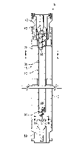
Referring now to Figure 5, a cross-sectional view of the reverse flow gas
separator 5 is
illustrated as a gas slug 100 enters the reverse flow gas separator 5. The gas
slug 100 is a large
volume of gas that is not dispersed in a liquid. The reverse flow gas
separator 5 comprises a
housing 10, a driveshaft 20, a head 45, and a base 50. In the illustrated
example, the gas slug 100
flows uphole in the annulus 85 between the well casing 90 and the production
string comprising
the reverse flow gas separator 5. The gas slug 100 enters into the first void
space 25 of the reverse
flow gas separator 5 by flowing into the housing intake 15 of the housing 10.
Gas exit ports 40
allow for the gas slug 100 to travel out of the first void space 25 and then
through the gas exit ports
Date Recue/Date Received 2021-06-01
40 within the head 45. Once through the gas exit ports 40, the gas slug 100
will have exited out of
the reverse flow gas separator 5 where it is dispersed back into the annulus
85.
A gas-free liquid portion 75 of a production fluid 70 remains in the first
void space 25 as
the gas slug passes. This liquid portion 75 was previously separated out of a
prior pumped
production fluid 70 (as described in Figure 4 above) which entered the reverse
flow gas separator
5 prior to the gas slug 100. The liquid level 105 in the first void space 25
drops as the gas slug 100
passes, thus allowing the remaining liquid portion 75 to function as a
reservoir which allows the
upstream pump to continue operation. The length of the reverse flow gas
separator 5 may be
extended to determine the volume of the supply reservoir provided. The longer
the reverse flow
gas separator 5, the larger the volume of fluid that may be kept in the
reservoir of the first void
space 25 in order to supply the pump in case a gas slug 100 is encountered.
After the gas slug 100
has passed, production fluid 70 may enter the reverse flow gas separator 5 as
described in the
example illustrated by Figure 4.
It is to be recognized that the reverse flow gas separator may also directly
or indirectly
affect the various downhole equipment and tools that may contact the reverse
flow gas separator
disclosed herein. Such equipment and tools may include, but are not limited
to, wellbore casing,
wellbore liner, completion string, insert strings, drill string, coiled
tubing, slickline, wireline, drill
pipe, drill collars, mud motors, downhole motors and/or pumps, surface-mounted
motors and/or
pumps, centralizers, turbolizers, scratchers, floats (e.g., shoes, collars,
valves, etc.), logging tools
and related telemetry equipment, actuators (e.g., electromechanical devices,
hydromechanical
devices, etc.), sliding sleeves, production sleeves, plugs, screens, filters,
flow control devices (e.g.,
inflow control devices, autonomous inflow control devices, outflow control
devices, etc.),
couplings (e.g., electro-hydraulic wet connect, dry connect, inductive
coupler, etc.), control lines
(e.g., electrical, fiber optic, hydraulic, etc.), surveillance lines, drill
bits and reamers, sensors or
distributed sensors, downhole heat exchangers, valves and corresponding
actuation devices, tool
seals, packers, cement plugs, bridge plugs, and other wellbore isolation
devices, or components,
and the like. Any of these components may be included in the apparatus,
methods, and systems
generally described above and depicted in Figures 1-5.
Provided are methods for separating gas from liquid in a wellbore. An example
method
comprises allowing a fluid to enter a reverse flow gas separator comprising a
housing, a first void
space within the housing, a driveshaft disposed adjacent to the first void
space, and a second void
11
Date Recue/Date Received 2021-06-01
space disposed within the interior of the drive shaft. The method further
comprises reversing the
flow of the fluid inside the reverse flow gas separator; wherein the fluid
comprises a liquid and a
gas. The method additionally comprises flowing the gas out of the first void
space and into the
wellbore; and flowing the liquid into the second void space.
Additionally or alternatively, the method may include one or more of the
following features
individually or in combination. The reverse flow gas separator may further
comprise a head
coupled to the housing. The head may comprise a gas exit port that is
fluidically connected to the
first void space and the wellbore. The gas exit port may be angled within the
head such that a first
opening of the gas exit port is positioned proximate the drive shaft and
further such that a second
opening of the gas exit port opens to the wellbore. The driveshaft intake may
comprise at least one
side that is angled inward at a direction and grade that is not perpendicular
with the driveshaft. The
housing intake may comprise at least one side that is angled inward at a
direction and grade that is
not perpendicular with the housing. The driveshaft may further comprise an
auger disposed within
the second void space. The first void space may be defined by the interior of
the housing and the
exterior of the driveshaft and further wherein the first void space is
continuous from the housing
intake to the driveshaft intake and is not divided within its dimensions. The
gas may be flowed out
of the first void space through a gas exit port that is fluidically connected
to the first void space
and the wellbore. The gas exit port may be disposed within a head and is
angled within the head
such that a first opening of the gas exit port is positioned proximate the
drive shaft and further such
that a second opening of the gas exit port opens to the wellbore. The
driveshaft may comprise a
driveshaft intake comprising at least one side that is angled inward at a
direction and grade that is
not perpendicular with the driveshaft. The second void space may be continuous
from the
driveshaft intake to an opening in a terminal end of the driveshaft. The
housing may comprise a
housing intake comprising at least one side that is angled inward at a
direction and grade that is
not perpendicular with the housing. The driveshaft may further comprise an
auger disposed within
the second void space. The first void space may be defined by the interior of
the housing and the
exterior of the driveshaft and further wherein the first void space is
continuous from the housing
intake to the driveshaft intake and is not divided within its dimensions.
Provided is a reverse flow gas separator. An example reverse flow gas
separator comprises
a housing having a housing intake; wherein there is a first void space within
the housing; and a
driveshaft disposed adjacent to the first void space; wherein the drive shaft
is hollow and comprises
12
Date Recue/Date Received 2021-06-01
a second void space disposed within the interior of the drive shaft; wherein
the second void space
is continuous from a driveshaft intake to an opening in a terminal end of the
driveshaft.
Additionally or alternatively, the reverse flow gas separator may include one
or more of
the following features individually or in combination. The reverse flow gas
separator may further
comprise a head coupled to the housing. The head may comprise a gas exit port
that is fluidically
connected to the first void space and the wellbore. The gas exit port may be
angled within the head
such that a first opening of the gas exit port is positioned proximate the
drive shaft and further such
that a second opening of the gas exit port opens to the wellbore. The
driveshaft intake may
comprise at least one side that is angled inward at a direction and grade that
is not perpendicular
with the driveshaft. The housing intake may comprise at least one side that is
angled inward at a
direction and grade that is not perpendicular with the housing. The driveshaft
may further comprise
an auger disposed within the second void space. The first void space may be
defined by the interior
of the housing and the exterior of the driveshaft and further wherein the
first void space is
continuous from the housing intake to the driveshaft intake and is not divided
within its
dimensions. The gas may be flowed out of the first void space through a gas
exit port that is
fluidically connected to the first void space and the wellbore. The gas exit
port may be disposed
within a head and is angled within the head such that a first opening of the
gas exit port is
positioned proximate the drive shaft and further such that a second opening of
the gas exit port
opens to the wellbore. The second void space may be continuous from the
driveshaft intake to an
opening in a terminal end of the driveshaft.
Provided are systems for separating gas from liquid in a wellbore. An example
system
comprises a reverse flow gas separator comprising a housing having a housing
intake; wherein
there is a first void space within the housing; and a driveshaft disposed
adjacent to the first void
space; wherein the drive shaft is hollow and comprises a second void space
disposed within the
interior of the drive shaft; wherein the second void space is continuous from
a driveshaft intake to
an opening in a terminal end of the driveshaft. The system further comprises a
pump upstream of
the reverse flow gas separator and fluidically connected to the second void
space.
Additionally or alternatively, the system may include one or more of the
following features
individually or in combination. Additionally or alternatively, the reverse
flow gas separator may
include one or more of the following features individually or in combination.
The reverse flow gas
separator may further comprise a head coupled to the housing. The head may
comprise a gas exit
13
Date Recue/Date Received 2021-06-01
port that is fluidically connected to the first void space and the wellbore.
The gas exit port may be
angled within the head such that a first opening of the gas exit port is
positioned proximate the
drive shaft and further such that a second opening of the gas exit port opens
to the wellbore. The
driveshaft intake may comprise at least one side that is angled inward at a
direction and grade that
is not perpendicular with the driveshaft. The housing intake may comprise at
least one side that is
angled inward at a direction and grade that is not perpendicular with the
housing. The driveshaft
may further comprise an auger disposed within the second void space. The first
void space may be
defined by the interior of the housing and the exterior of the driveshaft and
further wherein the
first void space is continuous from the housing intake to the driveshaft
intake and is not divided
within its dimensions. The gas may be flowed out of the first void space
through a gas exit port
that is fluidically connected to the first void space and the wellbore. The
gas exit port may be
disposed within a head and is angled within the head such that a first opening
of the gas exit port
is positioned proximate the drive shaft and further such that a second opening
of the gas exit port
opens to the wellbore. The second void space may be continuous from the
driveshaft intake to an
opening in a terminal end of the driveshaft.
The preceding description provides various examples of the systems and methods
of use
disclosed herein which may contain different method steps and alternative
combinations of
components. It should be understood that, although individual examples may be
discussed herein,
the present disclosure covers all combinations of the disclosed examples,
including, without
limitation, the different component combinations, method step combinations,
and properties of the
system. It should be understood that the compositions and methods are
described in terms of
"comprising," "containing," or "including" various components or steps. The
systems and methods
can also "consist essentially of' or "consist of the various components and
steps." Moreover, the
indefinite articles "a" or "an," as used in the claims, are defined herein to
mean one or more than
one of the element that it introduces.
For the sake of brevity, only certain ranges are explicitly disclosed herein.
However, ranges
from any lower limit may be combined with any upper limit to recite a range
not explicitly recited,
as well as ranges from any lower limit may be combined with any other lower
limit to recite a
range not explicitly recited. In the same way, ranges from any upper limit may
be combined with
any other upper limit to recite a range not explicitly recited. Additionally,
whenever a numerical
range with a lower limit and an upper limit is disclosed, any number and any
included range falling
14
Date Recue/Date Received 2021-06-01
within the range are specifically disclosed. In particular, every range of
values (of the form, "from
about a to about b," or, equivalently, "from approximately a to b," or,
equivalently, "from
approximately a-b") disclosed herein is to be understood to set forth every
number and range
encompassed within the broader range of values even if not explicitly recited.
Thus, every point
or individual value may serve as its own lower or upper limit combined with
any other point or
individual value or any other lower or upper limit, to recite a range not
explicitly recited.
One or more illustrative examples incorporating the examples disclosed herein
are
presented. Not all features of a physical implementation are described or
shown in this application
for the sake of clarity. Therefore, the disclosed systems and methods are well
adapted to attain the
ends and advantages mentioned, as well as those that are inherent therein. The
particular examples
disclosed above are illustrative only, as the teachings of the present
disclosure may be modified
and practiced in different but equivalent manners apparent to those skilled in
the art having the
benefit of the teachings herein. Furthermore, no limitations are intended to
the details of
construction or design herein shown other than as described in the claims
below. It is therefore
evident that the particular illustrative examples disclosed above may be
altered, combined, or
modified, and all such variations are considered within the scope of the
present disclosure. The
systems and methods illustratively disclosed herein may suitably be practiced
in the absence of
any element that is not specifically disclosed herein and/or any optional
element disclosed herein.
Although the present disclosure and its advantages have been described in
detail, it should
be understood that various changes, substitutions and alterations can be made
herein without
departing from the spirit and scope of the disclosure as defined by the
following claims.
Date Recue/Date Received 2021-06-01