Language selection

Search

Patent 3120759 Summary

Third-party information liability

Some of the information on this Web page has been provided by external sources. The Government of Canada is not responsible for the accuracy, reliability or currency of the information supplied by external sources. Users wishing to rely upon this information should consult directly with the source of the information. Content provided by external sources is not subject to official languages, privacy and accessibility requirements.

Claims and Abstract availability

Any discrepancies in the text and image of the Claims and Abstract are due to differing posting times. Text of the Claims and Abstract are posted:

  • At the time the application is open to public inspection;
  • At the time of issue of the patent (grant).
(12) Patent: (11) CA 3120759
(54) English Title: DETONATOR CONSTRUCTION
(54) French Title: CONSTRUCTION DE DETONATEUR
Status: Granted and Issued
Bibliographic Data
(51) International Patent Classification (IPC):
  • F42D 1/04 (2006.01)
(72) Inventors :
  • BIRKIN, CHRISTOPHER MALCOLM (South Africa)
  • KRUGER, MICHIEL JACOBUS (South Africa)
  • MICHNA, RICHARD JOSEPH (South Africa)
  • KOEKEMOER, ANDRE LOUIS (South Africa)
  • JURRAS III, MARK IVAN (South Africa)
(73) Owners :
  • DETNET SOUTH AFRICA (PTY) LTD
(71) Applicants :
  • DETNET SOUTH AFRICA (PTY) LTD (South Africa)
(74) Agent: OYEN WIGGS GREEN & MUTALA LLP
(74) Associate agent:
(45) Issued: 2023-07-11
(86) PCT Filing Date: 2020-01-24
(87) Open to Public Inspection: 2020-08-06
Examination requested: 2021-06-09
Availability of licence: N/A
Dedicated to the Public: N/A
(25) Language of filing: English

Patent Cooperation Treaty (PCT): Yes
(86) PCT Filing Number: PCT/ZA2020/050006
(87) International Publication Number: WO 2020160572
(85) National Entry: 2021-05-20

(30) Application Priority Data:
Application No. Country/Territory Date
2019/00554 (South Africa) 2019-01-28

Abstracts

English Abstract

A detonator which includes a tube with an open end, a shock tube, secured to a plug which is fixed to an open end of the tube, an electronic module inside the tube, the module including a substrate which carries electronic components, and sensing structure mounted to the substrate spaced from an opposing end of the shock tube.


French Abstract

L'invention concerne un détonateur qui comprend un tube ayant une extrémité ouverte, un tube à choc, fixé à un bouchon qui est fixé à une extrémité ouverte du tube, un module électronique à l'intérieur du tube, le module comprenant un substrat qui porte des composants électroniques, et une structure de détection montée sur le substrat espacée par rapport à une extrémité opposée du tube à choc.

Claims

Note: Claims are shown in the official language in which they were submitted.

7
CLAIMS
1.
A detonator (10) which includes a tubular casing (12) with a closed end (28)
and an
open end (30), a base charge (14) inside the casing (12) adjacent an inner
surface (38)
of the closed end (28), an electronic module (16) which is located inside the
casing (12),
the electronic module (16) including a body (50) of a plastics material (52),
an electronic
circuit which comprises a substrate (40) and electronic components (42), at
least a part
of the electronic circuit which includes the electronic components (42) being
embedded
in the plastics body (50) with a portion (58) of the substrate (40) projecting
from the
body (50), the body (50) including a first end (54) from which said portion
(58) of the
substrate (40) projects and a second end (56) which opposes the base charge
(14), a
housing (66) which is mounted to the projecting portion (58) of the substrate
(40) and
which is spaced from the first end (54) of the body (50), the housing (66)
including a
passage (84) which extends through the housing (66) from an inlet (86) to an
outlet
(88), a sensing structure (70) mounted to the substrate (40) opposing the
outlet (88)
from the housing (66), a plug (18) which is located at least partly in the
open end (30) of
the casing (12) and which is sealingly engaged with the casing (12), and a
shock tube
(20) with an end (92) which is secured to the plug (18) and which opposes the
inlet (86)
to the housing (66) thereby to direct a shock tube event emitted at the end
(92) of the
shock tube (20) upon ignition of the shock tube (20), through the passage (84)
onto the
sensing structure (70).

8
2. A detonator (10) according to claim 1 wherein the casing (12) is made
from any one of a
composite material, a plastics material, and a metal or alloy.
3. A detonator (10) according to claim 1 or 2 wherein the electronic
circuit includes a
sensing component (64) which is located at the first end (54) of the body (50)
positioned
in the plastics material (52) and wherein at least a portion (58) of the
plastics material
(52) which overlies the sensing component (64) is light transparent.
4. A detonator (10) according to claim 3 wherein the sensing component (64)
is a light
sensor (64).
5. A detonator (10) according to any one of claims 1 to 4 wherein the
plastics body (50) is
formed with a formation into which a part (98) of the tubular casing (12) is
crimped, in
an interengaging manner, thereby to ensure that the body (50) is correctly
positioned
inside the casing (12).
6. A detonator (10) according to claim 1 wherein the first end (54) of the
body (50)
opposing the outlet (88) from the housing (66) is tapered.

Description

Note: Descriptions are shown in the official language in which they were submitted.


CA 03120759 2021-05-20
WO 2020/160572
PCT/ZA2020/050006
1
DETONATOR CONSTRUCTION
BACKGROUND OF THE INVENTION
[0001] This invention relates to constructional details of a detonator which
is initiated by a
shock tube event. This type of arrangement is described for example in the
specification of
US patent number 8967048.
[0002] In a detonator of the kind referred to, it is important for the various
components of the
detonator to be arranged in a particular configuration to ensure optimum
reliability and safety.
Arduous conditions can exist at a blast site and the detonators which are to
be used must be
capable of functioning reliably after being handled, and installed in
demanding situations. In
that respect physical factors relating to constructional aspects of the
detonator are as important
as electronic techniques which are used to validate and subsequently to
implement a firing
signal in a reliable manner consistent with designed parameters.
[0003] An object of the present invention is to provide a detonator which
meets the
aforementioned requirements.
SUMMARY OF THE INVENTION
[0004] The invention provides a detonator which includes a tubular casing with
a closed end
and an open end, a base charge inside the casing adjacent an inner surface of
the closed end,
an electronic module which is located inside the casing, the electronic module
including a body
of a plastics material, an electronic circuit which comprises a substrate and
electronic
components, at least a part of the electronic circuit being embedded in the
plastics body with

CA 03120759 2021-05-20
WO 2020/160572
PCT/ZA2020/050006
2
a portion of the substrate projecting from the body, the body including a
first end which opposes
the base charge and a second end from which said portion of the substrate
projects, a housing
which is mounted to the projecting portion of the substrate and which is
spaced from the second
end of the body, a sensing structure mounted to the substrate at the housing,
a plug which is
located at least partly in the open end of the casing and which is sealingly
engaged with the
casing, and a shock tube with an end which is secured to the plug and which
opposes the
sensing structure thereby to direct a shock tube event emitted at the end of
the shock tube
upon ignition of the shock tube, onto the sensing structure.
[0005] The casing may be made from any appropriate material e.g. a composite
material, a
plastics material or an appropriate metal or alloy.
[0006] A sensing component included in the electronic circuit may be located
at the second
end of the body positioned in the plastics material. The sensing component may
be of any
suitable kind. If the sensing component is a light sensor then at least a
portion of the plastics
material which overlies the light sensor is light transparent.
[0007] The plastics body may be formed with a first formation into which a
part of the tubular
casing can be crimped, in an interengaging manner, thereby to ensure that the
body is correctly
positioned inside the casing.
BRIEF DESCRIPTION OF THE DRAWINGS
[0008] The invention is further described by way of example with reference to
the
.. accompanying drawings in which:

CA 03120759 2021-05-20
WO 2020/160572
PCT/ZA2020/050006
3
Figure 1 is a side view of a detonator according to the invention,
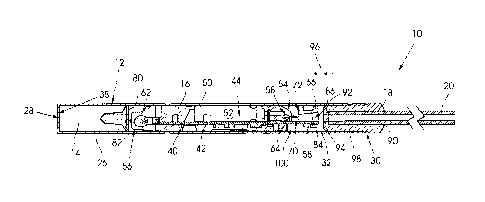
Figure 2 illustrates from one side and in cross section constructional details
of the detonator of
Figure 1; and
Figure 3 is a perspective view of a portion of an electronic module included
in the detonator.
DESCRIPTION OF PREFERRED EMBODIMENT
[0009] Figure 1 is a side view of a detonator 10 according to the invention.
Figure 2 illustrates
from one side and in cross section the detonator 10.
[0010] The detonator 10 includes a tubular casing 12 of any suitable material,
a base charge
14, an electronic module 16, a plug 18 and a shock tube 20.
[0011] In this example the tubular casing 12 includes a thin copper wall 26
and has a closed
end 28, an open end or mouth 30 and a bore 32.
[0012] The base charge 14 is of a known composition of a kind used in
detonators and is
placed in the bore 32 of the casing 12 and moved to abut an inner surface 38
at the closed end
28.
[0013] The electronic module 16 includes a substrate 40 which embodies a
printed circuit
board. Various electronic components 42 are mounted to the substrate 40 and
are
interconnected in a known manner. Also mounted to the substrate 40 is a
battery 44 which is
used to power the detonator 10. The module 16 further includes a body 50 which
is moulded
from a transparent plastics material 52 in which the components 42, 44 and a
greater portion
of the substrate are embedded. The body has a first end 54 and a second end
56. A portion

CA 03120759 2021-05-20
WO 2020/160572
PCT/ZA2020/050006
4
58 of the substrate 40 projects from the first end 54. An ignition element 62
is located at the
second end 56. A light sensor 64 is embedded in the body 50 at the first end
54.
[0014] A housing 66 is mounted to the projecting portion 58 of the substrate.
Sensing structure
70 is mounted to the projecting portion 58 of the substrate 40. The housing 66
has an end 72
which is spaced from the first end 54 of the body 50.
[0015] The body 50 is cylindrical.
[0016] During assembly the module 16 is precisely positioned in the bore 32
using automated
techniques, so that the second end 56 is spaced from an opposing surface 80 of
the base
charge 14 by a predetermined and controlled distance 82. The casing 12 is then
crimped at a
location 12A so that the casing is mechanically or frictionally locked to the
module 16. A portion
of the body 50 adjacent the crimp location 12A does not include any of the
electronic
components 42. Thus the body 50 can be cylindrically compressed during the
crimping
process without directing any resultant stress onto electronic components
which could be
damaged by that type of mechanical force.
[0017] The housing 66 is configured to fit with minimal clearance into the
bore 32. A passage
84 extends through the housing 66 from an inlet 86 to an outlet 88.
[0018] The plug 18 has a central passage 90. An end 92 of the shock tube 20 is
located in
the passage 90 and secured thereto. A thin diaphragm 94 inside the plug 18
abuts the end
92 of the shock tube 20. The diaphragm 94 prevents the migration of a shock
tube explosives
composition to the housing 64. It is conceivable that particles from the
explosives composition
could interfere with the integrity and working of some of the electronic
components 42

CA 03120759 2021-05-20
WO 2020/160572
PCT/ZA2020/050006
embodied in the module 16. The end 92 is spaced from the inlet 86 of the
housing 66 by a
distance 96 which is precisely controlled by automated means during assembly
of the
detonator 10. The plug 18 is fixed to the casing 12 by means of crimps 98.
During the crimping
process the plug 18 is compressed in one direction and expands in an axial
direction towards
5 the housing 66. The distance 96 becomes minimal.
[0019] In use of the detonator 10 the shock tube 20 is initiated and a shock
tube event which
contains plasma and light and which is accompanied by an increase in
temperature and a
pressure wave is emitted from the end 92, ruptures the diaphragm 94 and
impacts on the
housing 66. The passage 84 guides the shock tube event to the sensing
structure 70 and to
the light sensor 64. The sensing structure 70 and the light sensor 64 are
designed to detect
characteristics which are uniquely associated with a genuine shock tube event.
These
characteristics are validated by a circuit which is included in the components
42, and provided
all aspects are determined to be functional, the battery 44 is used to provide
energy to fire the
ignition element 62 which, in turn, causes initiation of the base charge 14.
[0020] An important feature of the detonator 10 is that the electronic
components 42 are held
embedded in the plastics body 50. However, at least one characteristic of the
shock tube event
is detected by the sensing structure 70 which is spaced from the body 50. On
the other hand
a light signal which is also characteristic of the shock tube event, is
detected by the sensor 64
which is protected by the transparent plastics material 52. In essence there
is a serial
arrangement in which the sensing structure 70 functions firstly and, although
there is only a
short time interval thereafter, the sensing component 64 then functions.

CA 03120759 2021-05-20
WO 2020/160572
PCT/ZA2020/050006
6
[0021] The housing 66 is spaced from the first end 54 so that particles and
energy associated
with the shock tube event are allowed to dissipate at least to some extent
into a volume 100
before the light signal reaches the first end 54 and the light sensor 64. In
order to enhance
such dissipation the first end 54, as is shown in Figure 2, is tapered at
least to some extent.
Additionally the taper is flanked by formations 102 and 104, in the form of
saw-tooth formations,
(Figure 3) which help to create turbulence and to trap particles, associated
with the shock tube
event, which otherwise might be reflected to the sensing structure 70. Only
the formations 102
are shown in Figure 3 but the formations 104, which are on an opposing side of
the module 16
are similar to the formations 102. Each formation 102, 106 has a flat surface
106 which is
transverse to a longitudinal axis 108 and a sloping surface 110 which is at an
acute angle
relative to the flat surface 106.

Representative Drawing
A single figure which represents the drawing illustrating the invention.
Administrative Status

2024-08-01:As part of the Next Generation Patents (NGP) transition, the Canadian Patents Database (CPD) now contains a more detailed Event History, which replicates the Event Log of our new back-office solution.

Please note that "Inactive:" events refers to events no longer in use in our new back-office solution.

For a clearer understanding of the status of the application/patent presented on this page, the site Disclaimer , as well as the definitions for Patent , Event History , Maintenance Fee  and Payment History  should be consulted.

Event History

Description Date
Letter Sent 2024-01-24
Inactive: Grant downloaded 2023-07-11
Letter Sent 2023-07-11
Grant by Issuance 2023-07-11
Inactive: Cover page published 2023-07-10
Pre-grant 2023-05-09
Inactive: Final fee received 2023-05-09
Letter Sent 2023-04-11
Notice of Allowance is Issued 2023-04-11
Inactive: QS passed 2023-02-20
Inactive: Approved for allowance (AFA) 2023-02-20
Inactive: Request Received Change of Agent File No. 2023-01-19
Amendment Received - Voluntary Amendment 2022-12-13
Amendment Received - Response to Examiner's Requisition 2022-12-13
Examiner's Report 2022-09-15
Inactive: Report - No QC 2022-08-23
Common Representative Appointed 2021-11-13
Inactive: Cover page published 2021-07-16
Letter Sent 2021-06-21
Letter sent 2021-06-16
Priority Claim Requirements Determined Compliant 2021-06-09
Request for Priority Received 2021-06-09
Inactive: IPC assigned 2021-06-09
Application Received - PCT 2021-06-09
Inactive: First IPC assigned 2021-06-09
Request for Examination Requirements Determined Compliant 2021-06-09
All Requirements for Examination Determined Compliant 2021-06-09
Request for Examination Received 2021-06-09
Amendment Received - Voluntary Amendment 2021-05-21
Inactive: IPRP received 2021-05-21
National Entry Requirements Determined Compliant 2021-05-20
Application Published (Open to Public Inspection) 2020-08-06

Abandonment History

There is no abandonment history.

Maintenance Fee

The last payment was received on 2023-01-12

Note : If the full payment has not been received on or before the date indicated, a further fee may be required which may be one of the following

  • the reinstatement fee;
  • the late payment fee; or
  • additional fee to reverse deemed expiry.

Please refer to the CIPO Patent Fees web page to see all current fee amounts.

Fee History

Fee Type Anniversary Year Due Date Paid Date
Basic national fee - standard 2021-05-20 2021-05-20
Request for examination - standard 2024-01-24 2021-06-09
MF (application, 2nd anniv.) - standard 02 2022-01-24 2022-01-17
MF (application, 3rd anniv.) - standard 03 2023-01-24 2023-01-12
Final fee - standard 2023-05-09
Owners on Record

Note: Records showing the ownership history in alphabetical order.

Current Owners on Record
DETNET SOUTH AFRICA (PTY) LTD
Past Owners on Record
ANDRE LOUIS KOEKEMOER
CHRISTOPHER MALCOLM BIRKIN
MARK IVAN JURRAS III
MICHIEL JACOBUS KRUGER
RICHARD JOSEPH MICHNA
Past Owners that do not appear in the "Owners on Record" listing will appear in other documentation within the application.
Documents

To view selected files, please enter reCAPTCHA code :


To view images, click a link in the Document Description column. To download the documents, select one or more checkboxes in the first column and then click the "Download Selected in PDF format (Zip Archive)" or the "Download Selected as Single PDF" button.

List of published and non-published patent-specific documents on the CPD .

If you have any difficulty accessing content, you can call the Client Service Centre at 1-866-997-1936 or send them an e-mail at CIPO Client Service Centre.


Document
Description 
Date
(yyyy-mm-dd) 
Number of pages   Size of Image (KB) 
Representative drawing 2023-06-12 1 16
Cover Page 2023-06-12 1 43
Claims 2021-05-20 2 47
Drawings 2021-05-20 2 39
Abstract 2021-05-20 1 69
Description 2021-05-20 6 211
Representative drawing 2021-05-20 1 22
Cover Page 2021-07-16 1 40
Claims 2022-12-13 2 89
Claims 2021-05-21 2 95
Courtesy - Letter Acknowledging PCT National Phase Entry 2021-06-16 1 587
Courtesy - Acknowledgement of Request for Examination 2021-06-21 1 437
Commissioner's Notice - Application Found Allowable 2023-04-11 1 580
Commissioner's Notice - Maintenance Fee for a Patent Not Paid 2024-03-06 1 542
Electronic Grant Certificate 2023-07-11 1 2,527
International search report 2021-05-20 3 87
National entry request 2021-05-20 5 180
Request for examination 2021-06-09 4 112
Examiner requisition 2022-09-15 3 140
Amendment / response to report 2022-12-13 9 264
International preliminary examination report 2021-05-21 13 704
Final fee 2023-05-09 4 100