Note: Descriptions are shown in the official language in which they were submitted.
CA 03120885 2021-05-21
WO 2020/142187
PCT/US2019/066506
TITLE OF INVENTION
Patent Application of Creative Toys, LLC, Hollis, NH, USA
and in the USA of
Brian D. Klauber, citizen of USA, 29 Jambard Road, Hollis, NH 03049,
Benjamin Gould, citizen of USA, 103 La Rue Place NW, Atlanta, GA 30327
Frank DeGiacomo, citizen of USA, Norwell, MA
and
Robert D. Klauber, citizen of USA, 1100 University Manor Dr, Condo 38B,
Fairfield, IA 52556;
CREATIVE CONSTRUCTION SET ADDITIONAL ACCESSORIES
CROSS-REFERENCE TO RELATED APPLICATIONS
(0001) n/a
REFERENCE TO SEQUENCE LISTING, A TABLE, OR A COMPUTER PROGRAM
LISTING COMPACT DISC APPENDIX BACKGROUND OF THE INVENTION
(0002) n/a
BACKGROUND OF THE INVENTION
Field of the Invention
(0003) This invention relates to creative accessories and modifications to a
construction set
known commercially as Swivel-Snaps, described in WO 2011/143019,
PCT/SU2011/035107,
US Patent 9,669,324, and other daughter/sister patents and patent applications
in the USA and
elsewhere, that provide additional advantages to users beyond that of the
construction set
invention shown in the afore cited documents.
1
CA 03120885 2021-05-21
WO 2020/142187
PCT/US2019/066506
Description of Related Art
(0004) Prior art for the Swivel-Snaps invention is described in the afore
cited
patent(s)/application(s). None show accessories or modifications to that
invention similar to
those shown herein.
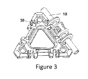
(0005) Fig. 1 shows a post connector 10 for the preferred embodiment of the
Swivel-Snaps
invention. Fig. 2 illustrates one type of component part, the triangle
component 30. Fig. 3 depicts
a post connector 10 and a triangle component part 30 connected together. Fig.
4 shows two such
triangle components 30 connected to a single post connector 10.
(0006) The post connector 10 in the preferred Swivel-Snaps embodiment of Fig.
1
comprises a post 12 of essentially rod-like shape with one or more disks 14
attached to, or
integral with, the post 12, wherein the axes of the post 12 and the disk(s) 14
are essentially co-
axial. In the preferred, and some other embodiments, the post connector may
also comprise a
cylindrical, or quasi-cylindrical, section, deemed herein, the connector guide
16. The axis of
connector guide 16 can be essentially co-axial with the axis of the post 12.
The term quasi-
cylindrical, as used herein, refers to a shape, such as that shown for the
connector guide 16 in
Fig. 1, which has a non-purely cylindrical surface on what would otherwise be
a cylinder. For
example, a quasi-cylindrical shape can be considered to be what was originally
a cylinder but
which has had its surface indented, protruded, curved, and/or perforated.
(0007) In Fig. 1, the connector guide 16 is quasi-cylindrical, having a
concave, indented
surface, and said surface has perforations, including radially directed holes
going completely
through from one side to the other. Such holes can be filled with an overmould
of rubber, plastic,
metallic or other material, and said overmould can be solid or hollow. These
perforations, and
indentions, are not necessary for the functioning of the invention, but can
add visual appeal, as
well as desirable features.
(0008) The connector guide 16 is a means to guide the connection between the
post
connector and a component part. It can also be a means to stabilize, align,
and/or strengthen the
connection, though it is not necessary to the invention.
(0009) The disk(s) 14 and/or the connector guide 16 can be attached via any
means to the
post 12, or alternatively, one or more of them can be an integral part, along
with post 12, of the
2
CA 03120885 2021-05-21
WO 2020/142187
PCT/US2019/066506
post connector 10, such as could be accomplished by casting, injection
molding, or other
processes. Although the post 12 is shown extending outside of the disks 14, it
is not necessary to
the invention for it to do so. In any embodiment, post 12 only needs to
support one or more disks
14 (or a means to connect the post to a component part), and that is what the
invention
comprises.
(0010) Component parts, such as triangle component 30 of Fig. 2, have cutouts,
typically
but not necessarily along their edges, into which portions of the post
connector 10 can be
inserted. Such cutouts comprise disk cutout(s) 31 and connector guide cutout
34. When portions
of the post connector 10, such as disk(s) 14 and/or connector guide 16 are
inserted into
respective cutouts 31 and/or 34, the post connector 10 and the component part
(triangle part 30
here) become connected. See Fig. 3. These cutouts can be large enough to
permit rotation of a
post connector 10 angularly about its long axis, relative to a component part
(30 here). In fact,
this is often desired, as it permits a hinging motion between the two parts,
and as well, between
sections of any further greater assemblies comprised of more post connectors
and component
parts. Alternatively, the cutouts can be small enough, or deliberately shaped,
relative to the size
of disk(s) 14 and/or connector guide 16, to effectively resist such angular
motion and provide a
non-hinge type of connection. Other kinds of restrictions, well known to those
skilled in the art,
can be used to provide a non-hinging connection, as well, and these are
comprised by the
invention.
(0011) Relief cutout(s) 32 can be used to enable easier snapping of a post
connector 10 to a
component part (30 in Fig. 2), and removal of same, while also providing a
hard stop to prevent
over-traveling the beam and potentially crack the latch member. Such relief
cutouts are
employed in this embodiment, but are not a necessary element of the invention.
The connector
guide cutout 34 is shown in Fig. 2 as straight and parallel to the triangle
edge direction, but any
suitable cutout is comprised by the invention. For best hinging effect, one or
more of the cutout
surfaces 36, 37, 38, 39, and 40 may be arc-like, to match the typically
circular edges of post 12,
disk(s) 14 and connector guide 16. However, any suitable geometry of such
surface(s) is
comprised by the invention, and none of those surfaces have to contact any
portion of post
connector 10.
(0012) Latch element 33, a cantilever employed in this embodiment, forms a
latch with disk
3
CA 03120885 2021-05-21
WO 2020/142187
PCT/US2019/066506
14. One way it can do this is via the "bump" or "lip" 41, shown in Fig. 2,
which snaps over the
outer part of disk 14. Latch element 33, in this embodiment, is also arc-like
along its inner facing
side in Fig. 2 to match the profile of disk 14. This provides for more fluid
hinging, though it is
not necessary for the functioning of the invention. Latch element 33, although
shown as a
cantilever, can also be a raised dot, or bump, or in fact, anything that
serves the same purpose as
latch element 33 shown herein. Further, the latching element may be on the
opposite side of disk
cutout 31 (i.e., on the inner surface of cutout 38, the side closer to
connector guide cutout 34).
Still further, latching elements may be on both sides of the cutout.
(0013) Element 14 comprises a geometric form that includes non-disk, as well
as disk
shapes, and shall be deemed herein a "cutout insertable element". Thus, the
cutout insertable
element shall be considered represented by the number 14 in all figures,
although in the preferred
embodiment of Figs. 1 to 3, it is disk-like. When the cutout insertable
element is disk-like in
shape, or an arc section of a full disk, we shall refer to it as a "disk".
When such disk extends
over a full 3600, we may sometimes refer to it as a "complete disk", or "3600
disk". The cutout
insertable element may be considerably thicker than the disk 14 shown in the
figures, and may
even be longer in the axial direction than its own diameter (or width in
direction perpendicular to
the axial.)
(0014) Holes 35 in the corners of triangle component part 30 are not essential
to the
functioning of the invention, but may aid with embellishments in certain
embodiments of the
invention. Also, holes 35 can be the same diameter as post 12 to enable
mounting of post
connectors 10, via their ends, into said holes.
(0015) Fig. 4 shows two triangle parts 30 connected to a single post connector
10. For
appropriate cutout to post connector portion tolerances, the two triangle
parts can move angularly
about the post connector, with respect to one another.
(0016) Fig. 5 depicts a square component part 80 connected to a post connector
10. Square
component 80 has cutouts like those shown for triangle component 30, to
facilitate connection
with post connector(s) 10.
(0017) Fig. 6 shows a faceplate 70 that can be inserted into a triangle
component part 30 for
the purpose of stiffening/strengthening the triangle component, for visual
appeal, and/or for
attaching post connector(s), other faceplate(s), pictures, decals, other
component part(s), or any
4
CA 03120885 2021-05-21
WO 2020/142187
PCT/US2019/066506
device that enhances the invention. The faceplate 70 displayed in Fig. 7 has
an optional hole 72,
which may, but does not necessarily have to, be in the center of the
faceplate. In other
configurations, there may be more than one hole, and any hole does not have to
be circular, but
can be any shape. The post portion of a post connector may be inserted into
such hole, and such
insertion can be snug enough to permit the post connector to be a part of an
assembly of post
connector(s) and component part(s). Other items, such as, but not limited to,
a wheel axle, flower
(artificial or real), rod, lollipop, flag, LED, and toy figure may be inserted
into the hole, as well,
or in lieu of the post connector.
(0018) Faceplates can also have cutouts or raised areas for the letters of the
alphabet,
numbers, words, etc., allowing children to study and/or snap together their
ABC's, name, party
invitation, age, etc. Any faceplate embellishments, such as those described
herein or otherwise,
can extend beyond the plane, and/or also beyond the edge(s), of any component
part. Further,
they can be quite thick and/or have hollow regions that may be filled with any
number of items,
such as, but not limited to, live fish, candy, glitter, lava lamp goo, etc.
They can comprise, or
allow attachment of, 3D items of many kinds. That is, faceplates can extend
upward in the
vertical direction of Fig. 7 to any reasonable height, and can extend sideways
(sideways as seen
in Fig. 7) to any reasonable extent. (See Fig. 43.) They can have knobs,
plugs, or other means,
threaded or otherwise, to attach any number of different items to them.
(0019) Both of the words "faceplate" and "facemount" may refer herein to
devices that are
either significantly extended in the vertical direction (away from a component
face) or thin in the
vertical direction (i.e., platelike.)
(0020) Fig. 7 depicts the faceplate 70 inserted into the triangle component
30. Although the
discussion of Figs 6 and 7 focus on holding the faceplate by its sides onto
the component part,
the component part can attach to some other region of the component part. For
example, the
component part may be solid in the middle with a knob or other protrusion onto
which a hole in
the faceplate fits. Alternatively, the faceplate may a have a knob or other
protrusion which fits
into a hole in the component part. Any means to hold a faceplate snugly in the
triangle, or any
other shape, component part, including simple snaps well known to those
skilled in the art, is
comprised by the invention.
(0021) Faceplates can be employed in square or any other shape component parts
in the
5
CA 03120885 2021-05-21
WO 2020/142187
PCT/US2019/066506
same fashion as described above for triangle component parts, and wherever the
words triangle
or triangular are used herein with respect to faceplates, the word "square"
may be substituted and
the result comprise the Swivel-Snaps invention.
(0022) The invention comprises decals, paintings, laser markings, pictures,
flags, mirrors,
tattoos, hand written sheets, and similar items attached to the faceplates,
though these are not
necessary. The invention comprises any of the items discussed anywhere herein
as being
attachable to a faceplate, as being also attachable to a component part and/or
a post connector.
(0023) Fig. 8 shows a post connector 10 with a single sphere 20 attached to
one end. Fig. 9
shows a post connector with two such spheres, one on either end. Such spheres
20 may be
rubber, plastic, wood, metal, or any suitable material. They may attach to the
post connector 10
via any means, many of which are well known to those skilled in the art.
Alternatively, the
spheres 20 could be manufactured as an integral part of the post connector 20
when the post
connector is made, via casting, injection molding, or similar process.
(0024) Alternatively, any suitable object or device may be attached to, or
inserted into, the
.. end of a post connector 10. These include, but are not limited to, hooks,
screw eyes, suction
cups, threaded rods, magnets, whistles, springs, hinges, toys, toy figures,
lollipops, wheel axles,
flowers (artificial or real), flashlights, LEDs, and bubble wands.
(0025) The Swivel-Snaps invention comprises square component 80 as well as all
possible
geometric shapes configured, as parts 30 and 80 are, to connect with a post
connector 10. These
other possible component part shapes include, but are not limited to,
rectangles, parallelograms,
pentagons, hexagons, all other polygons, circles, ovals, all other effectively
2D (thin in one
dimension) shapes, rectangular solids, tetrahedrons, spheres, ovoids, all
other 3D solids, and
portions/sections of any of the foregoing.
(0026) With these various types of component parts, a user of the invention
can create
innumerable different types and sizes of structures. One can connect
components of different
types together. For example, the triangle component part 30 can be connected
along an edge to a
square component part 80 via the same post connector 10. Boxes, homelike
structures, pyramids,
geometric forms of many diverse kinds, animal and bird models, dinosaurs (such
as
pterodactyls), and more are possible. The nature of the connections made
between the post
.. connectors 10 and component parts will provide significant stability and
durability to these
6
CA 03120885 2021-05-21
WO 2020/142187
PCT/US2019/066506
structural creations.
(0027) Given the swinging (i.e., hinge) capability of the connection between
post connector
and component part, any component part in any structure can be configured to
swing open or
closed. This can provide a door, which can be opened and closed, for house-
like structures,
5 hinged lids for boxes/chests, model window shutters, book binders, and
much more.
(0028) Fig. 10 shows square component parts 80 connected via post connectors
10 to form a
box (cube type of rectangular solid with one face hinged open in Fig. 10).
This box has a
swinging top (lid) that opens and closes because it swings freely about a post
connector, while
the other parts of the box remain stationary. Of course, any face of the box,
not just the top, may
10 be used for swinging open and closed while the others remain fixed, and
more than one face may
swing open, as well.
(0029) Faceplates such as, but not limited to, 70 and 84 do not need to snap
firmly into place
and be held tightly by their associated component part (30 and 80 in the
figures). Rather, they
could be attached along their outer edge to the inner edge of a component part
via a post
connector 10 or any other form of removable connection. This would permit
hinging or removal
of the faceplates with respect to their associated component parts, and
thereby provide for greater
creative expression by children using the invention. Such faceplates could
then become doors to
house-like structures, lids for boxes, etc.
OBJECTS AND ADVANTAGES OF THE INVENTION
(0030) Accordingly, several objects and advantages of the present invention
are to provide
greater stability, strength, flexibility, and/or ease of assembly of 2D and 3D
structures, typically
in construction assemblies, over those of prior art. Other objects and
advantages comprise greater
flexibility in types of structures, including, but not limited to, integration
of Swivel-Snaps with
other construction assembly kits such as Lego, K'Nex, and others, as well as
integration with
other toys and devices such as spinners, piggy banks, massagers, magnifying
lens, art supplies,
rails, periscopes, and more. Still other objects and advantages comprise new
type component
parts, means for building different types of creations, and more, for Swivel-
Snaps. Among other
things, these objects and advantages, as well as others, provide greater
utility, enjoyment, and
7
CA 03120885 2021-05-21
WO 2020/142187
PCT/US2019/066506
creative possibilities for users.
(0031) These and other aspects of the invention discussed below provide
significant benefits
and advantages over prior art. Further objects and advantages of the invention
will become
apparent from a consideration of the ensuing description of it.
BRIEF SUMMARY OF THE INVENTION
(0032) The present invention provides significant advantages over prior art
structural
building systems by utilizing the following unique embodiments for use with
Swivel-Snaps.
(0033) Piggy bank made from Swivel-Snaps, spinner attached, Lego studs and
Lego holes in
Swivel-Snaps parts/connectors/faceplates, integration options with
Duplo/Bristle
Blocks/K'Nex/magnets/Lego/etc., half/partial component part faces (Lego on
sides or edges),
rails (for example, around elongated "post"; Mobius strip as one embodiment),
interior/exterior
blocks (for axles, for example), periscope, unique faceplates (smell, Velcro,
hole for post ball,
chalk board surface, paint surface, white board surface), lens magnifier,
triangles in corners of
constructions, post connector art supplies, double component part, Swivel-
Snaps gears, fabric or
elastic faceplates (trampoline effect), and tubes through which marbles,
balls, or other objects
can pass connected to Swivel-Snaps elements. The invention also comprises
wheel attachments,
spherical object elements, construction figurines, and mock animal elements.
(0034) The invention, in its various embodiments, provides numerous advantages
over prior
art in a superior and wholly satisfactory manner.
BRIEF DESCRIPTION OF THE DRAWINGS
(0035) Figure 1 depicts one embodiment of the post connector of the Swivel-
Snaps
invention.
(0036) Figure 2 illustrates a triangle shaped component part of the Swivel-
Snaps invention.
(0037) Figure 3 shows an embodiment with post connector and a triangle
component
attached together of the Swivel-Snaps invention.
8
CA 03120885 2021-05-21
WO 2020/142187
PCT/US2019/066506
(0038) Figure 4 depicts a post connector attached together with two triangle
components of
the Swivel-Snaps invention.
(0039) Figure 5 shows a square component part with a post connector attached
of the
Swivel-Snaps invention.
(0040) Figure 6 shows a faceplate for a triangular component part with an
optional hole of
the Swivel-Snaps invention.
(0041) Figure 7 shows a faceplate inserted into a triangular component part of
the Swivel-
Snaps invention.
(0042) Figure 8 illustrates a single sphere mounted on the end of a post
connector of the
Swivel-Snaps invention.
(0043) Figure 9 depicts a post connector with spheres on each end in the
Swivel-Snaps
invention.
(0044) Figure 10 shows a cubic rectangular solid made from square component
parts and
post connectors in the Swivel-Snaps invention.
(0045) Figure 11 displays a square component part with a faceplate having a
slot in the
center for coins to pass through.
(0046) Figure 12 illustrates the combination of a spinner with Swivel-Snaps.
(0047) Figure 13 shows Lego studs and holes in Swivel-Snaps faceplates,
component parts,
and post connectors.
(0048) Figure 14 depicts several different types of connecting mechanisms used
in
commercially sold toys incorporated into Swivel-Snaps elements.
(0049) Figure 15 shows different types of connecting mechanisms used in
commercially
sold toys incorporated into one, or a few, sides of Swivel-Snaps component
parts.
(0050) Figure 16 depicts rails incorporated into a Swivel-Snaps connector.
9
CA 03120885 2021-05-21
WO 2020/142187
PCT/US2019/066506
(0051) Figure 17 shows a component part sliding on rails incorporated into a
Swivel-Snaps
connector.
(0052) Figure 18 illustrates a curved rail Swivel-Snaps connector.
(0053) Figure 19 shows a few different ways the rail Swivel-Snaps connector
can be shaped.
(0054) Figure 20 depicts a railed Swivel-Snaps connector using posts and less
material.
(0055) Figure 21 shows a block attached to a Swivel-Snaps component part that
can add
strength to constructions.
(0056) Figure 22 demonstrates some unique types of faceplates.
(0057) Figure 23 displays a faceplate with a magnifying lens.
(0058) Figure 24 shows art supplies incorporated into a Swivel-Snaps
connector.
(0059) Figure 25 depicts a fabric or elastic material faceplate.
(0060) Figure 26 shows a double length component part.
(0061) Figure 27 illustrates a gear and how it can engage with a Swivel-Snaps
construction
to provide motion and/or drive.
(0062) Figure 28 displays a right isosceles triangle support.
(0063) Figure 29 depicts a periscope with mirror faceplate polyhedrons inside
a tube made
of Swivel-Snaps elements.
(0064) Figure 30 shows an assembly whereby marbles or other balls may slide
inside tubes
of Swivel-Snaps constructions.
(0065) Figures 31 to 34 display a wheel, wheel assembly, and attachment to
component
parts to permit building of a vehicle, or used horizontally as a spinner or
carousel.
(0066) Figures 35 to 38 show a means for constructing a quasi-spherical
object.
(0067) Figures 39 to 43 depict a construction figurine.
CA 03120885 2021-05-21
WO 2020/142187
PCT/US2019/066506
(0068) Figures 44 to 48 illustrate various mock animals that can be
constructed from sub-
elements.
DETAILED DESCRIPTION OF THE INVENTION
(0069) Figs. 1 to 10 show various elements, embodiments, and configurations of
the Swivel-
.. Snaps invention cited in the preamble. Figure 10 shows a rectangular solid
made of square
Swivel-Snaps component parts and post connectors. The present invention is a
supplemental, i.e.,
"add-on" feature and/or a modification of the Swivel-Snaps invention.
(0070) The component part of Figure 11, with a slot 502 in the faceplate 84 in
the middle of
the component part 80 may be used for one of the component parts 80 in Figure
10. Thereby the
resulting structure can be used, with the top component part 80 in Figure 10
connected via post
connectors 10 such that the resulting structure is a closed rectangular solid
(a cube in the
embodiment of Figure 10), as a "piggy bank", i.e., a means for saving coins
and bills, a personal
savings bank. The component parts 80 shown as squares can be any suitable
shape, and the piggy
bank could thus be any possible 3D solid shape, not necessarily a cube. Some
possible such
.. shapes include a pyramid, a ball, an animal such as a pig, horse, or duck,
a wheel or more,
Instead of faceplates 84, the component parts can be solid or nearly solid,
across the middle
portion with a slot 502 in the middle portion. In essence, the user can create
a custom piggy
bank.
(0071) As storage needs increase, the user can simply add additional component
parts, such
as, but not limited to, 80 connected by post connectors and increase the size
and volume for
holding coins, trinkets, stones, shells, jewelry, candy, or other things. The
savings device is
expandable, portable, and easily opened and closed.
(0072) Figure 12 shows the addition of a spinner 512 to the Swivel-Snaps
invention. The
spinner, which can include bearings and/or weights, can be connected to a
faceplate 84, a post
connector 10, and/or a component part such as a square 80, or any shape. The
connection can be
anywhere on any element in Swivel-Snaps. For example, in Figure 12, the
spinner 512 is shown
11
CA 03120885 2021-05-21
WO 2020/142187
PCT/US2019/066506
attached to the end of a post connector 10, and also to the mid-section, the
connector guide in
that particular figure. The spinner can be connected at any angle as well with
respect to any
Swivel-Snaps element. The spinners can be pre-connected in the production
process to any such
element, or they can be connectable to any such element by the end user via
any suitable
connection mechanism. That is, the spinners can be attached to, integral with,
or attachable to
any Swivel-Snaps element, including, but not limited to, component parts of
any shape and size,
post connectors, and faceplates. They can be attachable anywhere on any of
those elements, at
any angle. The term "fidget spinner" as used herein in the broadest sense can
refer to any type of
spinning device that is attachable, via any means, method, and/or mechanism to
any Swivel-
.. Snaps element.
(0073) Figure 13 shows studs 602 (male) and holes (or cups) 604 (female) of
the Lego
design incorporated into Swivel-Snaps elements. In the figure, these elements
are faceplates 584,
570; component parts 580, 530; and post connectors 510, 512, 514, 516. This
allows joint
constructions to be made that comprise both Swivel-Snaps and Lego elements.
The Lego studs
and holes (or cups) can be anywhere on any Swivel-Snaps element, in any
number, and at any
orientation, although a preferred alignment is to have such studs and holes
(cups) in one or more
rows, comprising at least two studs and two holes in a row. The term "Lego"
when used herein
with regard to connection mechanism, design, studs, and/or holes refers to
studs, cups into which
said studs are inserted, and/or holes into which said studs are inserted,
wherein the studs may be
(in a preferred embodiment, but not necessarily are) cylindrical, or quasi-
cylindrical, in shape
and aligned in one or more rows, such as those shown in Figures 13, 14, and
15. The present
invention comprises any means, method, device, and/or mechanism that permits
connecting any
Swivel-Snaps element to such Lego type construction element by incorporating
connection
mechanism(s) or device(s) of said Lego type construction element (such as
studs, cups, or holes)
on, or into, a Swivel-Snaps element. The word "hole" used in such context can,
alternatively,
mean "cup" or "insertable section/piece/part/element" or "female
section/piece/part/element",
12
CA 03120885 2021-05-21
WO 2020/142187
PCT/US2019/066506
and in fact, any of those terms may be used interchangeably with any other and
still comprise the
present invention. The word "stud" used in such context can mean a pole, rod,
knob, disk, bump
or any other type of male element. The word "cup" can mean a cylindrical or
other shape piece,
at least partially hollow, into which a stud is inserted in order to make a
connection. The term
"Lego type" can refer to connection types other than those specifically and
commercially known
as Lego. Or it can refer to the specific, commercial Lego connection type, if
so defined
explicitly.
(0074) In Figure 14 several options for integrating Swivel-Snaps with
commercially
available toy construction systems are shown. These permit Swivel-Snaps users
to build joint
structures/objects with other toy systems. Examples shown include Duplo female
614 and male
612 connectors on Swivel-Snaps faceplates 684 ; Bristle Block connectors 702
on Swivel-Snaps
faceplates 784; K'Nex, male 802 and female 804 connectors on Swivel-Snaps
faceplates 884;
Lego male 602 and female 604 connectors, and magnetic faceplate inserts 984.
K'Nex
connections have a male portion comprising a rod with a lip (indention,
cutout, ledge) at the end
allowing the rod to form a sturdy connection with the female portion. Bristle
Block connections
have an array of bristles (male portion) where the female portion is between
the male bristles.
Connections for Lincoln Logs are also comprised by the present invention.
Although Figure 14
explicitly shows faceplates, the integrations with other toy construction
systems that is described
can also be built directly into a component part without a faceplate. The
present invention
comprises any means, method, device, and/or mechanism that connects any Swivel-
Snaps
element to another (additional) type of construction element by incorporating
connection
mechanism(s) of said other type of construction element on, or into, a Swivel-
Snaps element
(post connector, component part, faceplate, figurine, or other element). The
additional (another)
type of construction element, may be, but is not limited to, a block,
figurine, geometric shape,
letter, number, picture, or drawing, and is connectable to any other element,
such as, but not
limited to a post connector or a component part or a faceplate, with a
connection mechanism
13
CA 03120885 2021-05-21
WO 2020/142187
PCT/US2019/066506
comprising male and female portions that may, or may not, be aligned in one or
more rows.
(0075) Enabling users to play with Swivel-Snaps and their existing (and
future) toys is
important. Extending the Swivel-Snaps faceplate to accomplish connections with
these other toys
is the essence of this invention. There are countless combinations, and space
prohibits recounting
all of them, but they all stem from the same basic inventive concept ... build
Swivel-Snaps
faceplates that incorporate one or more of the fastener elements from a given
external toy system
(e.g., Lego, K'Nex, Duplo, Velcro, Lincoln Logs, magnetic toys, etc.) These
faceplates can be
built to support male or female or both connection types. These faceplates
may, or may not,
compromise the original Swivel-Snaps traditional functionalities. Although
square faceplates and
component parts are shown in Figure 14, the invention comprises all possible
shapes of such
elements. Compatibility with other construction sets is a big advantage of the
present invention.
(0076) Figure 15 shows partial (half or otherwise) Swivel-Snaps component
parts 584, 586,
886 that have connectability with other Swivel-Snaps components on one, or
only some, edges,
and otherwise may be connected to other construction set elements. Any of
these component
parts may be partial (less than full), or half the typical Swivel-Snaps
component part. It may
sometimes be valuable to only expose the Swivel-Snaps connection elements on
one, or a few,
side(s) of a component part. Some such cases, when working with another toy
set (Lego, K'Nex,
etc), are shown in Figure 15 . This is applicable to all Swivel-Snaps
elements, including, but not
limited to, component parts, post connectors, and faceplates. Fasteners and
component parts can
be inline, perpendicular, or set at any angle. Elements such as those shown in
Figure 15 allow
unique types of constructions not otherwise feasible.
(0077) Figures 16 to 20 depict embodiments of the Swivel-Snaps invention
having a
connector 610 with rails 614 upon which component parts such as a square 80
(but not limited to
a square) can be attached such that the component parts either become fixed to
the rails, or
alternatively, are able to slide along the rails (see arrow in Figure 17).
While only a single rail
614 is comprised by the invention, any number is also comprised by the
invention. The preferred
14
CA 03120885 2021-05-21
WO 2020/142187
PCT/US2019/066506
embodiment has two rails 614 as in Figure 16.
(0078) Figures 16 to 20 show connectors without connector guides 16 (see
Figure 1) but
embodiments with connector guides on connector 610, as well as any other
connector with rails
such as, but not limited to, 612, 614, 618, 620, are also comprised by the
invention.
(0079) Figure 18 illustrates one non straight possibility 612 for the
connector with rails.
Looking down from the top, as the views are in Figure 19, any possible shape
for the connector
is comprised by the invention. Just some of these shapes for connectors 610,
612, 618, 620 are
rails 614 are shown in Figure 19. Other possible shapes include, but are not
limited to, circular,
triangular, square, strip, alphabet letters, numbers, symbols, stepped,
pentagon, hexagon,
octagon, any regular or irregular polygon, and more. Another is that of a
Mobius strip. In
general, the invention comprises any configuration with rails on a connector.
The rails and
connector can be formed into any desirable shape.
(0080) Figure 20 shows one configuration, of many possible configurations, of
a railed
connector 611 in which cylindrical (or other non circular cross section) posts
are used to hold the
rails, rather than the continuous configurations of Figures 16, 17, 18, and
19. This embodiment
would save material cost. Note that any configuration of connector at all that
has rails upon with
Swivel-Snaps component parts or faceplates may be connected and either fixed
or slid comprises
the invention. The rails do not have to be continuous around an entire
connector, but can
comprise one or more discrete sections that do not surround a connector.
(0081) All of the remarks made herein with regard to component parts being
connected with
rails also hold for faceplates being connected to rails. All rails may be
attached to, attachable to,
or integral with a post or the main part of a connector body, a faceplate, or
another component
part. That is, in addition to the embodiments shown with rails as part of
connectors, the rails may
also be part of a faceplate or another component part. Component parts in any
embodiment any
shape and not just that of the square shown in Figures 16 and 17.
CA 03120885 2021-05-21
WO 2020/142187
PCT/US2019/066506
(0082) The inclusion of rails 614 in the Swivel-Snaps invention enables
additional building
opportunities such as, but not limited to, incorporation with trains and
roller coasters.
(0083) Figure 21 displays an embodiment of the invention with a block 550
mounted inside
a component part 80 wherein the block does not interfere with post connectors
that would attach
to the component part. The block 550 may be shaped such that its end fits
snugly inside the
component part 80. This configuration provides strength to assemblies due to
the inherent
strength of the block. It can carry significant loading. In one configuration,
the block may have a
wheel axle attachable to, attached to, or integral with it. This would allow
for
car/truck/train/other shells made of Swivel-Snaps to hang from a robust block
chassis. The
component part into which the block 550 is mounted does not have to be a
square 80, but may be
a triangle, other polygon, or any suitable shape.
(0084) Figure 22 shows several unique Swivel-Snaps faceplates. Faceplate 570
is made of
Velcro or has Velcro attached, or attachable to, it. This will enable unique
attachment scenarios.
For example, a fabric flame trail that attaches via Velcro to the bottom of a
Swivel-Snaps rocket
.. ship construction.
(0085) Faceplate 572 has a "scratch and sniff' surface. One scratches the
surface, and the
faceplate emits a smell. Faceplate 576 has a hole in it that receives a post
connector's ball end
20. (See figure 10.) This allows for ball joint assemblies that have a wide
range of motion yet
still 'snap' into place. Swivel-Snaps with the features of Figure 22 will
appeal to sight, sound,
touch, and smell. In addition to embodiments of unique faceplates shown in
Figure 22, other
configurations comprised by the invention are faceplates of, or containing,
chalk board surface,
paint surface, sticker surface, lenticular surface, mirror surface, and/or
white board surface.
Additionally, a component part may have any of the features described herein
for a faceplate.
(0086) Although Figure 22, and other figures, show a particular shape of
component part
(square 80 in Figure 22, for example), all embodiments herein described for
one particular shape
component part are applicable to component parts and faceplates of all
possible shapes and sizes.
16
CA 03120885 2021-05-21
WO 2020/142187
PCT/US2019/066506
Further all embodiments comprise post connectors (and elongated connectors
such as shown in
Figure 16 to 20) with, or without, connector guides 16. (See Figure 1.)
(0087) Figure 23 shows a Swivel-Snaps component part 80 with a faceplate
having a built-
in magnifying glass, i.e., a lens 590. The lens can be attached to, attachable
to, or an integral part
of the faceplate, or it may be the faceplate itself is a lens. User can
thereby inspect object under
magnification inside or outside structures they build. Using such lens
configurations as shown in
Figure 23, or otherwise, users can build microscopes or telescopes out of
Swivel-Snaps elements.
(0088) Figure 24 illustrates incorporation of art supplies such as a crayon,
pen, pencil, felt
tip marker, or paint brush 594 into a post connector 592. The post connector
592 may be filled
with crayon, pencil, pen, marker, paint, or the like material. The centers
could be exposed by
spinning the post connector, by mimicking the common spring loaded pen or
mechanical pencil
designs. Users can snap together a shape then extend the drawing tips so they
can draw 1 to N
lines at a time and the lines will remain perfectly parallel. Or the user
could use the design to
draw an arc 596 as the pen tip 594 rotates around a post connector. Or as
shown in the right hand
side of Figure 24, the disk of the post connector 592 could have marker
material, ink, or similar
that draws a line (an arc in the figure) as it is rotated.
(0089) Art supplies, such as those mentioned above and others, can also be
incorporated into
faceplates or component parts. Additionally, such art supplies can be attached
to, attachable to,
or integral with a post connector, faceplate, and/or component part.
(0090) In Figure 25 the faceplate 680 is made of fabric or elastic material
that will enable
trampoline, catapult, slingshot, and/or basketball shooting game functionality
to Swivel-Snaps.
The fabric can have a string or other material/object sewn to the center of it
to form a pull strap
682 so the user can pull on the elastic fabric. This creates a mini
trampoline/slingshot for users to
attack castles or other structures (made of Swivel-Snaps or not); to bounce
marbles, balls or other
things off of; act as a trampoline for dolls or other figures; shoot baskets;
be a "carnival type"
game; and more. Leveraging the swiveling post connector, the user could alter
the launch angle
17
CA 03120885 2021-05-21
WO 2020/142187
PCT/US2019/066506
until they hit their target. In larger component parts they may actually be
trampolines for kids
Elastic material is attached to, or attachable to, a component part wherein
when connected, an
object such as a ball or marble may be propelled by pulling back and releasing
the elastic
material, or said object may be bounced off of the elastic material.
(0091) A double size component part 632 is shown in Figure 26. This has the
same effective
width as the edge of a square component part 80, but a length that is
effectively twice that of a
square component part edge. It can accommodate two post connectors 10 on the
long edge, and
therefore connect two component parts, such as, but not limited to, the square
80 along that long
edge. Such a double size component part has more strength than two single size
component parts
80 connected together via a post connector 10. Of course, any shape component
parts, not just
the square shape, can be connected along the long edge of 632.
(0092) Additionally, a double size component part may be formed using the
shape(s) of any
one or two single component parts, not just that of the square shape. For
example, a solid double
triangle, i.e., a parallelogram, may be formed that has two 60 angle corners,
and two 120 angle
corners. As other examples, such a double component part could be formed based
on two
triangular shapes that are other than equilateral. As still other examples,
double component parts
could be formed from combinations of shapes such as hexagons, pentagons,
squares, triangles,
and other polygons. The component parts do not have to be of the same type.
For example, a
double component part could be formed from a triangle 30 and square 80, or
from any other two
different types of component parts. A double size component part essentially
has one edge that
can connect to two post connectors 10.
(0093) Triple, quadruple, and larger size component parts can be made based on
any number
of single component part shapes. The defining characteristic of a multiple
size component part is
that is can connect with more than one post connector 10 on at least one edge.
(0094) Figure 27 illustrates a gear 640 which can be used with Swivel-Snaps
constructions,
such as that shown in the top of the figure. This can enable motion and/or
provide drive. In the
18
CA 03120885 2021-05-21
WO 2020/142187
PCT/US2019/066506
image, End A can be connected to End B to form a 3D belt/loop/chain. One can
then place the
keys of a Swivel-Snaps compatible gear 640 into the square component part 80
center voids.
This can enable users to design moving creations, mobile structures, vehicles.
It could be
powered by a hand crank attached to the gear or by attaching a motor to the
gear. Other shape
component parts, other than squares 80 may be used as well.
(0095) Triangles 650 are added to the corners of a Swivel-Snaps construction
in Figure 28.
These can provide additional strength and support to structures. The triangle
650 in Figure 28 is
a right isosceles triangle, which should be the most commonly needed type for
strengthening
structures, but any suitable triangle shape that can be used for such support
is comprised by the
invention. This type of triangle increases the possible types of constructions
that can be built.
(0096) Figure 29 shows a periscope built using Swivel-Snaps elements and a
faceplate
polyhedron 660 with a mirror on one side. With two such faceplates 660 one can
align them
inside a Swivel-Snaps created passageway, or tube, with right angles as shown
in Figure 29. That
is, the mirrored faceplates 660 can be placed such that incident light on the
first of them is
.. reflected to the second of them, and typically then into a viewer's eye(s).
The mirror faceplate
660 can have an essentially triangular cross section in the plane of travel of
the light beam as
shown in Figure 29, although any suitable shape is comprised by the invention.
The mirror face
can be essentially square or rectangular, though again, any suitable shape is
comprised by the
invention. Flat mirrors can be used for best periscope type results. Curved
(convex or concave)
can be used to enlarge (as in a telescope) or reduce images. Distorted shape
mirrors, such as but
not limited to rippled mirrors, can be used for fun house type image viewing.
The angles in the
Swivel-Snaps passageway, or tube, do not have to be right angles, but can be
of any degree.
(0097) Figure 30 illustrates the incorporation of a separate tube 672 into a
Swivel-Snaps
construction of component parts 80 (or any other shapes of component parts)
and post connectors
10. By doing this, users can put a ball, marble 670, toy car, or other object
in one end, typically
the upper end, and the object (ball or marble 670 in Figure 30) can come out
the other end. The
19
CA 03120885 2021-05-21
WO 2020/142187
PCT/US2019/066506
tube 672 could instead be a chute, ramp, rail, tethering line, zip line, or
any other means to guide
the object along, through, or beside a Swivel-Snaps construction. Typically,
gravity will pull the
object downward, but any other means to propel or pull the object is comprised
by the invention,
as well.
(0098) A clamp 674 or other fastener by which the tube or other means for
guidance of the
object can be fastened may be attached to, attachable to, or integral with a
component part 80,
such as that shown in Figure 30. Such clamps or other fasteners can also be
attached to,
attachable to, or integral with any other Swivel-Snaps element, such as a post
connector or a
faceplate or any other shape component part. Typically, the tube or other
means for guidance
would snap into the clamp 674 or other fastener.
(0099) Figure 31 shows parts 925, 930, 935 that can be assembled to permit
attachment of a
wheel 925 to any component part (such as, but not limited to a square 80 or
triangle 30) or any
structure considered or implied herein. The wheel itself 925 can be of any
style, design, and/or
function and is not restricted to the particular design shown in Figure 31,
although that is the
.. preferred embodiment. That embodiment has ribs or spokes 928 and a rim 927.
The center of the
wheel comprises a means (such as 926 in this embodiment) to connect the wheel
component to a
shaft, axle, or assembly 930, and that shaft/axle/assembly has a means to
connect to a faceplate
935. In the embodiment shown, the means to connect the wheel 925 to the
shaft/axle/assembly
comprises a hollow shaft 926 in the center of the wheel 925 into which the
rod/shaft/axle 931 can
be inserted. A part of the shaft/axle/assembly 932 can help to hold the
rod/shaft/axle 931 in the
hollow shaft 926. This may be of any suitable design. The invention comprises
any means
(structural or otherwise) to connect a wheel to a component part.
(00100) In the embodiment shown in Figure 31, the means to connect to a
faceplate 935 is
an insert 934 that inserts into an opening, hole, cutout 936, or hollow
section in the faceplate
935. The design may be such that a twisting motion around the axis of the
rod/shaft/axle 931
tightens the shaft/axle/assembly 930 into the faceplate 935, but this is not
necessary for the
CA 03120885 2021-05-21
WO 2020/142187
PCT/US2019/066506
functioning of the invention. Any means to attach the shaft/axle/assembly 930
into the faceplate
935 is comprised by the invention. The faceplate 935 can be attached to a
component part, such
as the square 80 shown in Figure 32. Although a square faceplate 935 fitting
into a square 80 is
shown in the figures, any shape faceplate attached to any shape component part
is comprised by
the invention.
(00101) Views perpendicular to the rod/axle/shaft 931 from the side of the
faceplate 935
and the side of the wheel 925 are shown in Figure 33. Although that and other
figures show an
"S" shape for the connection between the shaft/axle/assembly 930 and the
faceplate
shaft/axle/assembly 935, any such shape and any suitable connecting means is
comprised by the
invention. Figure 34 shows a typical vehicle constructed out of triangle
component parts 30 and
square component parts 80 employing the present wheel assembly invention with
wheels 925.
(00102) The invention comprises a wheel that may be attachable to (or an
integral part of) a
shaft, axle, or assembly wherein that shaft, axle, or assembly may be
attachable to (or an integral
part of) a faceplate, and wherein that faceplate may be attachable to (or an
integral part of) a
component part. Note that although particular parts 925, 930, 935, and 80 are
shown as
attachable to one another in the figures, Any two or more of such parts may be
integral with one
another rather than attachable to one another. In fact, the entire assembly
shown in Figure 33,
other than the post connectors 10, may be integral, i.e., all of a single
piece. However,
embodiments in which the wheel may rotate relative to the component part (such
as a square 80
or a triangle 30) are more practical embodiments of the invention.
(00103) The invention comprises any means or method by which a wheel or wheel
assembly may be attached to a component part such that vehicles with one or
more wheels may
be constructed from component parts, at least one wheel, and possibly other
components. It also
comprises the wheel as a spinner or carousel, in which it is not necessarily
part of a vehicle.
(00104) Figure 35 shows a partial spherical section 915 which may be used to
construct a
spherical, nearly spherical, essentially spherical, quasi-spherical, or
approximately spherical
21
CA 03120885 2021-05-21
WO 2020/142187
PCT/US2019/066506
shape. The term quasi-spherical is one way to describe shapes such as the one
shown in Figure
38 for which some sections (sections where the post connectors 10 are in the
figure) are not part
of spherical surface, but most of the rest of the object is comprised of
sections that are portions
of a spherical surface. The surface 916 is essentially a portion of a
spherical surface. The "S"
figure 917 on the surface shown in the figure is not a requirement of the
invention, but merely a
design intended for a particular production run of the invention. In the
preferred embodiment
shown, insert 918 fits inside of a square component part 80 and holds, or
helps to hold, the
partial spherical section 915 in the square component part. See Figure 36.
Edge 919 typically
meets along the edge of the square component part, but that is not a
requirement of the invention
(although it is part of the preferred embodiment shown.)
(00105) Figure 37 shows one partial spherical section 915 attached to a cube
made of
square component parts 80 and post connectors 10. Figure 38 depicts a near,
effective, essential,
quasi-, or approximate, sphere made from the cube of component parts 80 and
post connectors
10 with six partial spherical sections 915 attached to the component parts.
(00106) A specific embodiment (the preferred embodiment) of the invention is
shown in
Figures 35 to 38, but the invention is not restricted to that particular
embodiment. Any means or
method whereby partial spherical sections may be attached to component parts
and a sphere, or
approximation to a sphere, may be constructed is comprised by the invention.
(00107) Figures 39 and 40 display a construction figurine 900 in the general
form of a
human, which may be attached to one or more post connectors 10. The
construction figurine has
arms 902 and legs 904. In the (preferred) embodiment shown, each arm has
pivots 906 at the
shoulder, pivoting elbows 903, and hands 908. Each leg has pivots at the hip
907, pivoting knees
905, and feet 910. The figurine has a head 911 and a torso 901.
(00108) Pivots at any of the shoulders, elbows, hips, knees (906, 903, 907,
and 905,
respectively) may be comprised of pins inserted into arm or leg sections,
around which each arm
or leg section may rotate, as is well known to those in the art. However, any
suitable means (not
22
CA 03120885 2021-05-21
WO 2020/142187
PCT/US2019/066506
constricted only to pins) for pivoting is comprised by the invention. For
example, the pivoting
could be achieved by mating sections of each arm or leg that, upon mating,
allow swiveling
without a pin. Such swivel mating of parts by various means is well known in
the art. Pivoting
elbows 903 and knees 905 are part of the preferred embodiment, but are not a
required part of the
invention. Pivoting of arms 902 and legs 904 are also part of the preferred
embodiment, but are
not a required part of the invention. The construction figurine 900 may simply
be without pivot
sections, yet have a form similar to a human or animal.
(00109) A hand 908 can be attached by a user to a post connector 10, and a
foot 910 can be
as well. In the preferred embodiment shown, the hands and feet are similar and
comprise cutouts
at the ends of the arms or feet, or equivalently, two extensions on either
side of each arm or leg.
These cutouts (or extensions) fit over the disk 14 (or component part
connecting element) snugly
so the arm or leg, and thus the entire construction figurine 900 may be
attached to post connector
10. The means for connecting hands and feet to post connectors shown is part
of the preferred
embodiment, but any such means is comprised by the invention.
(00110) Figure 41 shows a construction figurine 900 with a post connector 10
attached to its
hands 908 and about to connect the same post connector to a structure with
component parts 80.
Figure 42 shows a construction figurine 900 attached to the disk (or component
part connecting
element) 14 of a post connector which is also connected to a component part of
a structure made
of component parts (and post connectors).
(00111) Figure 43 displays a construction figurine attached to a structure
(below the
construction figurine) of component parts 80 and a post connector 10 via its
feet 910, and
simultaneously attached to a component part 30 (above and which could be part
of a larger
structure not shown) via its feet 908 and the disk 14 of a post connector 10.
Thus, the
construction figurine 900 can be used not merely as a decorative item, but as
a structural
component in building assemblies. It has utility. Because it can connect to
more than one post
connector and thus more than one component part or substructure, it can itself
be an element
23
CA 03120885 2021-05-21
WO 2020/142187
PCT/US2019/066506
used in the construction process and as part of final assembled constructions.
The figurine has
arms and feet attachable to the component part connecting element of the post
connector,
wherein such attachment provide structural strength and allows construction of
additional types
of construction assemblies. .
(00112) Although a human form is shown for the construction figurine 900, the
invention
also comprises the form of any animal with two feet and two arms, four feet,
or (hypothetically)
four arms. It also comprises means for connection via the hands and feet to
different
substructures via faceplates or component parts, rather than just via post
connectors.
(00113) Thus, the invention comprises a construction figurine, of human,
animal, or other
form, whose hands and feet can connect with post connectors, component parts,
faceplates,
and/or different substructures to build structural assemblies, and thus act as
a structural element
in such assemblies. It is also comprised simply of feet 910 that may connect
to post connectors,
component parts, faceplates, and/or different substructures without hands 908
being able to do
so. Likewise, it is also comprised simply of hands 908 that may connect to
post connectors,
component parts, faceplates, and/or different substructures without feet 910
being able to do so.
In such cases, one foot (hand) could connect to one part of a post connector,
component part,
faceplate, and/or different substructure and the other foot (hand) could
connect to another such
part. By so doing the construction figurine would have the utility of being a
construction element
in a construction assembly.
(00114) Figure 44 shows a building made of component parts (30 and 80), post
connectors
10 and additional elements including a chimney 942, windows 940, and a door
941 The
additional elements can be attached to component parts, faceplates, or post
connectors. This can
be in similar fashion to the partial spherical sections 915 of Figures 35 to
38, the wheels of
Figures 31 to 35, the figurines of Figures 39 to 43, or via any other means.
(00115) Figure 45 shows a chameleon made from component parts, post
connectors, a head
944, feet 946, and a tail 945, where the latter three are toy parts of the
animal and may be
24
CA 03120885 2021-05-21
WO 2020/142187
PCT/US2019/066506
attached via any of the means discussed for Figure 44.
(00116) Figure 46 displays a caterpillar made from component parts, post
connectors,
antenna 947, feet 949, and arms 948, where the latter three are toy parts of
the animal and may
be attached via any of the means discussed for Figure 44.
(00117) Figure 47 illustrates a chicken made from component parts, post
connectors, a head
950, wings 952, and a tail 951, where the latter three are toy parts of the
animal and may be
attached via any of the means discussed for Figure 44.
(00118) Figure 48 shows an airplane model constructed from component parts,
post
connectors, a pilot control section 954, wings 955, and a tail 956, where the
latter three may be
attached via any of the means discussed for Figure 44.
(00119) Although the figures show much detail, such details are not essential
to the
invention. The drawings merely show special cases, or embodiments, of the
invention. The
essential elements of the invention are recited in the claims.
(00120) Wherever herein the present invention is referred to as comprised in
part of
"Swivel-Snaps", that term is interpreted to mean the invention described in WO
2011/143019,
PCT/SU2011/035107, US Patent 9,669,324, and other daughter/sister patents and
patent
applications in the USA and elsewhere. Language, definitions, and terms used
in those patents
and patent applications are applicable to, relevant to, and interpretable in
the context of the
description and claims herein.
(00121) In particular, the term Swivel-Snaps, in its preferred embodiment, is
equivalent to a
structural assembly device comprising, a) a component part having
predetermined shape and a
post connector connecting element, and b) a post connector comprised of a post
and a component
part connecting element wherein said component part connecting element is
structurally
connected to said post by any means, including being integral with said post,
wherein at least
part of said component part connecting element is substantially displaced
radially from a central
CA 03120885 2021-05-21
WO 2020/142187
PCT/US2019/066506
axis of the post, wherein said at least part of said component part connecting
element is
connectable directly with said post connector connecting element, such that
when connected,
said at least part of said component part connecting element contacts said
post connector
connecting element, wherein said post connector and a plurality of said
component parts may be
mechanically connected in an angular direction around the post via said
component part
connecting element and a plurality of said post connector connecting elements
to form a
structure, such that, when connected, said component parts can swing
independently relative to
the post about said central axis of the post,
(00122) One use for the invention described in this patent application is as a
"toy, but the
invention is not limited to toys, and is applicable to any and all structural,
and/or other, uses.
(00123) This invention can thus be seen to have significant, novel advantages
over the prior
art delineated in the above "Description of Prior Art" section.
(00124) While the above description contains many specificities, the reader
should not
construe these as limitations on the scope of the invention, but merely as
exemplifications of
preferred embodiments thereof. Those skilled in the art will envision many
other possibilities
that are within its scope.
(00125) Accordingly, the scope of the invention should be determined not by
the
embodiments described, but by the appended claims and their legal equivalents.
26