Note: Descriptions are shown in the official language in which they were submitted.
CA 03122795 2021-06-07
THREADED CONNECTION FOR STEEL PIPE
BACKGROUND
Technical Field
[0001] The present disclosure relates to a threaded connection for steel pipe.
Description of the Background Art
[0002] Steel pipes called oil-well pipes are used, for example, for
prospecting
or producing oil or natural gas in oil wells or natural-gas wells (hereinafter
collectively referred to as "oil wells" or the like), developing non-
conventional
resources such as oil sand or shale gas, retrieving or storing carbon dioxide
(Carbon dioxide Capture and Storage (CCS)), geothermal power generation,
or in hot springs. A threaded connection is used to connect steel pipes.
[0003] Such threaded connections for steel pipes are generally categorized
as coupling type and integral type. A coupling-type connection connects a
pair of pipes, one of which is a steel pipe and the other one is a coupling.
In
this case, a male thread is provided on the outer periphery of each of the
ends of the steel pipe, while a female thread is provided on the inner
periphery of each of the ends of the coupling. Then, a male thread of the
steel pipe is screwed into a female thread of the coupling such that they are
made up and connected. An integral-type connection connects a pair of
pipes that are both steel pipes, and does not use a separate coupling. In this
case, a male thread is provided on the outer periphery of one end of each
steel pipe, while a female thread is provided on the inner periphery of the
other end. Then, the male thread of one steel pipe is screwed into the
female thread of the other steel pipe such that they are made up and
connected.
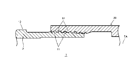
[0004] A connection portion of a pipe end on which a male thread is provided
includes an element to be inserted into a female thread, and thus is usually
referred to as "pin". A connection portion of a pipe end on which a female
thread is provided includes an element for receiving a male thread, and thus
is referred to as "box". A pin and a box constitute ends of pipes and are thus
tubular in shape.
[0005] When threaded connections are used at shallow levels in very deep
oil wells, for example, large tensile loads derived from oil-well pipes' own
weights are applied to threaded connections, while large compression loads
1
Date Recue/Date Received 2021-06-07
due to thermal expansion are applied to threaded connections at deep levels.
[0006] U.S. Reissue Patent No. 30647 (Patent Document 1), U.S. Patent No.
6158785 (Patent Document 2) and WO 2015/194193 (Patent Document 3)
each disclose a threaded connection using wedge threads. A wedge thread
has a thread width that gradually changes as it goes along its helical
direction. A wedge thread is also known as dovetailed thread, and provides
high torque performance. However, none of Patent Documents 1 to 3
specifies at what rate the thread width of their wedge threads changes.
[0007] JP 2012-512347 A (Patent Document 4) also discloses a threaded
connection using wedge threads. In areas near the ends of the male-thread
region, both the lead as measured between male stabbing flanks and the lead
as measured between male loading flanks are constant. Similarly, in areas
near the ends of the female-thread region, both the lead as measured
between female stabbing flanks and the lead as measured between female
loading flanks are constant. Consequently, thread width is constant near
the ends of the threaded regions. Although it can be recognized that there
is a difference between the lead as measured between loading flanks and the
lead as measured between stabbing flanks, the document specifies no specific
value for this difference.
[0008] The following prior art documents are noted.
[0009] [Patent Document 1] U.S. Reissue Patent No. 30647
[Patent Document 2] U.S. Patent No. 6158785
[Patent Document 3] WO 2015/194193
[Patent Document 41 JP 2012-512347 A
SUMMARY
[0010] Since the loading flank and stabbing flank of a wedge thread have
negative flank angles, wedge threads exhibit high torque performance as
they interlock during make-up. Further, to facilitate make-up, a wedge
thread may have a thread-crest width that decreases as it goes toward the
tip of the pin or box. In other words, there is a difference between the
loading-flank pitch and stabbing-flank pitch. This difference in pitch may
be referred to as "delta lead". The delta lead determines the thread-crest
widths as measured near the tips of the pin and box.
[0011] Instead of delta lead, wedge ratio may be used to take the effect of
the
2
Date Recue/Date Received 2023-02-06
CA 03122795 2021-06-07
absolute value of the thread pitch into consideration. The wedge ratio is
determined by dividing the delta lead by the loading-flank pitch and is the
ratio of the delta lead to the loading-flank pitch, expressed as a percentage.
[0012] If the wedge ratio is high, this means that the rate at which the
thread-crest width decreases is also high. If the wedge ratio is high, the
thread-crest width decreases near the tip of the pin or box. If the
thread-crest width is small, the wedge thread may not be able to resist a
large tensile load, and the thread crest itself may be broken. Care is thus
needed in deciding the wedge ratio. The ability of a wedge thread to resist a
tensile load will be hereinafter referred to as "tension performance".
[0013] Patent Document 4 (JP 2012-512347 A), listed above, discloses
optimizing wedge ratio. However, there is no document that evaluates the
effect of the wedge ratio on torque performance as well as tension
performance.
[0014] An object of the present disclosure is to provide a threaded
connection for steel pipe that provides both high torque performance and
high tension performance.
[0015] The present inventors did extensive research to find an appropriate
wedge ratio that improves both torque performance and tension performance.
They found out that both high torque performance and high tension
performance will be achieved by changing the wedge ratio.
[0016] A threaded connection for a steel pipe according to the present
disclosure includes a tubular pin and a tubular box. The tubular pin is
formed by one tip portion of the steel pipe. The tubular box is made up on
the pin as the pin is inserted into the box. The pin includes a male thread.
The male thread is provided on an outer periphery of the pin, and is a wedge
thread. The box includes a female thread. The female thread corresponds
to the male thread and is provided on an inner periphery of the box, and is a
wedge thread. The threaded connection satisfies the following expression,
(1):
[00171 3 % < (LP¨SP)/LP < 8 % (1).
[0018] In expression (1), LP is the pitch between loading flanks of the male
thread. SP is the pitch between stabbing flanks of the male thread.
BRIEF DESCRIPTION OF THE DRAWINGS
[0019] [FIG. 1] FIG. 1 is a longitudinal cross-sectional view of a threaded
3
Date Recue/Date Received 2021-06-07
CA 03122795 2021-06-07
connection for steel pipe according to an embodiment, taken along the
pipe-axis direction.
[FIG. 2] FIG. 2 is an enlarged longitudinal cross-sectional view of the
male and female threads of FIG. 1.
[FIG. 3] FIG. 3 is a graph illustrating the relationship between wedge
ratio and yield torque for a loading-flank pitch of 8.64 mm.
[FIG. 41 FIG. 4 is a graph illustrating the relationship between wedge
ratio and yield torque for a loading-flank pitch of 10.8 mm.
[FIG. 51 FIG. 5 is a graph illustrating the relationship between wedge
ratio and yield torque for a loading-flank pitch of 7.2 mm.
[FIG. 6] FIG. 6 is a graph illustrating the relationship between wedge
ratio and equivalent plastic strain for a loading-flank pitch of 8.64 mm.
[FIG. 7] FIG. 7 is a graph illustrating the relationship between wedge
ratio and equivalent plastic strain for a loading-flank pitch of 10.8 mm.
[FIG. 8] FIG. 8 is a graph illustrating the relationship between wedge
ratio and equivalent plastic strain for a loading-flank pitch of 7.2 mm.
DETAILED DESCRIPTION OF THE PREFERRED EMBODIMENTS
[0020] A threaded connection for a steel pipe according to the present
embodiment includes a tubular pin and a tubular box. The tubular pin is
formed by one tip portion of the steel pipe. The tubular box is made up on
the pin as the pin is inserted into the box. The pin includes a male thread.
The male thread is provided on an outer periphery of the pin, the male
thread being a wedge thread. The box includes a female thread. The
female thread corresponds to the male thread and provided on an inner
periphery of the box, the female thread being a wedge thread. The threaded
connection satisfies the following expression, (1):
[00211 3 % < (LP¨SP)/LP < 8 % (1).
[0022] In expression (1), LP is the pitch between loading flanks of the male
thread. SP is the pitch between stabbing flanks of the male thread.
[0023] Preferably, the threaded connection satisfies the following expression,
(2).
[0024] 4 % < (LP¨SP)/LP < 7 % (2).
[0025] The threaded connection may satisfy the following expression, (3).
[00261 ¨10 degrees < a < ¨1 degree (3).
[0027] In expression (3), a is the flank angle of the loading and stabbing
4
Date Recue/Date Received 2021-06-07
CA 03122795 2021-06-07
flanks of the male thread.
[00281 The male thread and the female thread may each include a
perfect-thread portion including a perfect thread. The perfect-thread
portion may have a length of 40 to 60 mm as measured in an axial direction
of the steel pipe.
[0029] The threaded connection for steel pipe according to the present
embodiment will now be described with reference to the drawings. The
same and corresponding components are labeled with the same characters in
the drawings, and the same description will not be repeated.
[0030] Referring to FIG. 1, a threaded connection for steel pipe according to
the present embodiment, denoted by 1, includes a tubular pin 10 and a
tubular box 20. The pin 10 is formed by one tip portion of a steel pipe 2.
The box 20 is made up on the pin 10 as the pin 10 is inserted into the box.
The portions of the steel pipe 2 other than the tip portion may be hereinafter
specifically referred to as "steel-pipe body".
[0031] The pin 10 includes a male thread 11. The male thread 11 is
provided on the outer periphery of the pin 10. The box 20 includes a female
thread 21. The female thread 21 corresponds to the male thread 11 and
provided on the inner periphery of the box 20. More specifically, the male
thread 11 is helically formed on the outer periphery of the pin 10. The
female thread 21 is helically formed on the inner periphery of the box 20.
Each of the male and female threads 11 and 21 is constituted by a tapered
thread. Each of the male and female threads 11 and 12 is constituted by a
wedge thread.
[0032] Referring to FIG. 2, the male thread 11 has a loading flank 111 and
the female thread 21 has a loading flank 211, both having a flank angle a.
The male thread 11 has a stabbing flank 112 and the female thread 21 has a
stabbing flank 212, both having a flank angle 6. The flank angle a is the
angle of the loading flanks 111 and 211 relative to a plane VP perpendicular
to the pipe axis (i.e. axis of the steel pipe 2) TA. The flank angle 6 is the
angle of the stabbing flanks 112 and 212 relative to a plane VP perpendicular
to the pipe axis TA. If the loading flanks 111 and 211 or the stabbing flanks
112 and 212 are parallel to a plane VP, their flank angle is zero degrees. If
the loading flank 111 of the male thread 11 is inclined toward the tip of the
pin 10 relative to the plane VP (in other words, if the loading flank 211 of
the
female thread 21 is inclined toward the tip of the box 20 relative to the
plane
Date Recue/Date Received 2021-06-07
CA 03122795 2021-06-07
VP), the flank angle a of the loading flanks 111 and 211 is positive. On the
contrary, if the loading flank 111 of the male thread 11 is inclined toward
the
steel-pipe body of the pin 10 relative to the plane VP (in other words, if the
loading flank 211 of the female thread 21 is inclined toward the steel-pipe
body of the box 20 relative to the plane VP), the flank angle a of the loading
flanks 111 and 211 is negative. Further, if the stabbing flank 112 of the
male thread 11 is inclined toward the steel-pipe body of the pin 10 relative
to
the plane VP (in other words, if the stabbing flank 212 of the female thread
21 is inclined toward the pipe body of the box 20 relative to the plane VP),
the flank angle of the stabbing flanks 112 and 212 is positive. On the
contrary, if the stabbing flank 112 of the male thread 11 is inclined toward
the tip of the pin 10 relative to the plane VP (in other words, if the
stabbing
flank 212 of the female thread 21 is inclined toward the tip of the box 20
relative to the plane VP), the flank angle of the stabbing flanks 112 and 212
is negative. The flank angles a and 8 of the wedge threads are both
negative.
[0033] Although not limiting, it is preferable that the entire male and
female threads 11 and 21 be constituted by perfect threads, with no
imperfect thread present. If the entire threads 11 and 21 are constituted by
perfect threads, this means an increased contact area between the male and
female threads 11 and 21, which improves torque performance. Each of the
perfect-thread portions (i.e. male and female threads 11 and 21 each
constituted by a perfect thread) has a length of 40 to 60 mm, for example.
[0034] The threaded connection 1 for steel pipe satisfies the following
expression, (1).
[0035] 3 % < (LP¨SP)/LP < 8 % (1).
[0036] Preferably, the threaded connection 1 for steel pipe satisfies the
following expression, (2).
[0037] 4 % < (LP¨SP)/LP < 7 % (2).
[0038] In expressions (1) and (2), LP is the pitch between loading flanks 111
of the male thread 11 (hereinafter referred to as "loading-flank pitch"). SP
is the pitch between stabbing flanks 112 of the male thread 11 (hereinafter
referred to as "stabbing-flank pitch"). (LP¨SP)/LP represents wedge ratio.
The loading-flank pitch LP is equal to the pitch between loading flanks 211 of
the female thread 21. The stabbing-flank pitch SP is equal to the pitch
between stabbing flanks 212 of the female thread 21.
6
Date Recue/Date Received 2021-06-07
CA 03122795 2021-06-07
[0039] That is, the upper limit of the wedge ratio is 8 %, and preferably 7 %.
The lower limit of the wedge ratio is 3 %, and preferably 4 %.
[0040] The threaded connection 1 for steel pipe satisfies the following
expression, (3).
[00411 ¨10 degrees < a < ¨1 degree and ¨10 degrees < 6 < ¨1 degree (3).
[0042] In expression (3), a is the flank angle of the loading flank 111 of the
male thread 11. 6 is the flank angle of the stabbing flank 112 of the male
thread 11. The flank angle a of the loading flank 111 of the male thread 11
may be equal to, or different from, the flank angle 6 of the stabbing flank
112
of the male thread 11. The flank angle a of the stabbing flank 111 of the
male thread 11 is substantially equal to the flank angle a of the loading
flank
211 of the female thread 21. The flank angle 8 of the stabbing flank 112 of
the male thread 11 is substantially equal to the flank angle 6 of the stabbing
flank 212 of the female thread 21.
[0043] Exactly stating, the values of the loading-flank pitch LP,
stabbing-flank pitch SP and flank angles a and 6 are those before make-up.
[0044] In the present embodiment, the male and female threads 11 and 21
are constituted by wedge threads and their wedge ratio is in the range of 3 to
8 %, thereby providing both high torque performance and high tension
performance.
[0045] The threaded connection 1 may be coupling type or integral type. A
coupling-type threaded connection includes two pins and a coupling. One of
the pins is formed by a tip portion of one steel pipe. The other pin is formed
by a tip portion of another steel pipe. The coupling includes two boxes.
One of the boxes is formed by one end portion of the coupling. The other box
is formed by the other end portion of the coupling. The one box is made up
on the one pin as the one pin is inserted therein. The other box is located at
the coupling end opposite to that with the one box, and is made up on the
other pin as the other pin is inserted therein. On the other hand, an
integral threaded connection is for connecting two steel pipes together, and
includes a pin and a box. In the case of an integral threaded connection, one
steel pipe includes a pin while the other steel pipe 2 includes a box.
[0046] Although an embodiment has been described, the present invention
is not limited to the above-illustrated embodiment, and various
modifications are possible without departing from the spirit of the invention.
7
Date Recue/Date Received 2021-06-07
CA 03122795 2021-06-07
EXAMPLES
[0047] To verify the effects of the present embodiment, torque performance
and tension performance were evaluated using the finite element method
(FEM). A wedge threaded connection was evaluated, and steel pipes
described below were used.
[0048] Size: 9-5/8 inches (with an outer diameter of the pipe body of 244.48
mm and an inner diameter of the pipe body of 216.8 mm)
Material: OCTG material L80 in accordance with the API standards
(with a nominal proof stress of YS=552 MPa (80 ksi))
Thread taper: 1/12
Thread length: 50 mm (pin) and 60 mm (box)
Thread height: 1.8 mm
Flank angle: ¨5 degrees (for both loading flank and stabbing flank)
Loading-flank pitch: 7.2 mm, 8.64 mm or 10.8 mm
Wedge ratio: 2 to 10 %
Stabbing-flank pitch: calculated backward based on wedge ratio
[0049] The threaded connection being evaluated was composed only by the
male thread 11 and female thread 21, as shown in FIG. 1. The male and
female threads 11 and 21 were entirely constituted by wedge threads and
perfect threads.
[0050] Table 1 shows the dimensions etc. of the 27 threaded connections (i.e.
samples) tested in the analysis.
8
Date Recue/Date Received 2021-06-07
0
0,
a
x Table 1
m..... . .. _ ..... .._ . ..
...
.0
- - LqwValeit plastic strain
.
.
A materia Thtead Thread Thread Flank Loariing- Stabbing-
Deka Wedge ' male thread' - tem* thread'
WV =
- - -
1,.). No, Size length height angle flank pitch flank pith
lead ratio
x I tM)efing Won] Emml
Meg] [niml Pron] film! EN RIM loatimg stabbing loading stabbing
ca
o
(0.
flank flank flank Rank
<
a 1 8467 0173 2.00%
39917 0_0158 0.0010 0.0256 0_0019
N,
0 .
r., 2 8.381 ,_. 0.259 ,
3.00% 53996.:0.0176 , 0.0033 0.0280 0-_0031 ,
6 3 8294 0.346 4.00%
55852 0.0208 0.0063 0.0299 0_0052
.;, 4 8.208
0.432 5_00% 56786 0_0217 0.0106 0_0344 0_0076
. 8,64 8.122 ' 0.518 '
6.00% -50438 0.0287 0.0148 0.0411 0.0110 '
6 8.035
0.605 7.00% 61087 0.0290 0.0182 0.0494 0_0154
7 7.949
0.691 ' 8.00% 61278 0_0378 0.0198 ' 0.0585
01)267
8 7.882 0.778 9_00%
61583 0.0644 0.0289 0.0745 0_0328 9
9 , 7.776 0.864
10_00% 61241 0.0640 0.0354 0.0904 01)481 .
,..
10.584 0.216 2.00% 41701 0.0620 0.0013 0.0255 0.0025 .
,.
_J
-,1,- 11
10.476 0.324 3.00% 44348 0.N85 0.0019 0.0254
01X/25
. . .
12 ,
10.368 , 0.432 _ 4.00% 46675 00669 , 0.0026 ,
0.0251 , 00025
,.
13 10.26
0.54 ... 5_00% 46710 0.0655 0_0035 0_0248
0,0026
14 9-5/8" 180 1112 50 1.8 -5 10.8
10.152 0.644 6.00% -47185 0.0642 ' 0.0449 -
0.0255 0_0027 .
.
.
10.044 0.756 7.00% 47577 0.0627 0.0060 0.0266
0_0027
_ _ , _ _ _
._ . õ . _ _._ .
'`-1-6 9_9..N1 0.864
8.00% 50531 0.0596 0.0087 0,0245 011089
,
17 9.828
0.972 9.00% . -51649 0.0571 0.0122 0.0318
0.0156
.._
18 9_72
1.08 10_00% 52568 01)421 0.0193 0_0557 0,0290
19 7.056 0.144 Z00%
58994 0.0305 0.0082 , 0.0134 0_0004
; 6.984
0.216' 3.00% ' 64600 0_0329 0.0108 0.0131 4,
0_0038
' 21 6.912
0.288 4.00% 67102 0.0368 0.0188 0.0146 01)067
n 6.84 , 0.36 5.00%
69646 0.0421 , 0.0207 , 0.0201 0.0097.
23 72 6.768 0.432 ,
6110% 71113 0.0489 0_0272 0.0335 _0_0125
24 6.696 0_504 7_00%
7097f 0_0561 0.0308 , 0.0463 0_0206 -
6.624 0.576 8.00% 72084 0.0648 0.0425 0.0593 0.0311
26 6.552
0.648 9.00% 72010 , 0.0651 0.0471 , 0.1136
0_0460
27 6_48
0.72 10.00% 70818 0_1378 , 0.0751 0.1381 awn
, _
. .__
CA 03122795 2021-06-07
[0051] For the analysis, the threaded connection 1 shown in FIG. 1 was used
as a base, to which changes in the dimensions of the male and female threads
11 and 21 were made, and torque performance and tension performance were
evaluated.
[0052] [Evaluation of Torque Performance]
Yield torque was defined as the maximum torque value (MTV) at
which make-up torque began to yield in the make-up torque chart, which
was used to evaluate torque performance.
[0053] [Evaluation of Tension Performance]
A load substantially equal to the tensile load under which the
threaded connection 1 yields was applied to a threaded connection that had
been made up, and the maximum value of the equivalent plastic strain
generated at the bases of the loading flanks 111 and 211 and stabbing flanks
112 and 212 of the thread located closest to the tip in each of the male and
female threads 11 and 21 was used to evaluate tension performance. From
experience in real-pipe tests, the present inventors know that the risk of a
break of a thread crest becomes high if equivalent plastic strain is as high
as
about 0.08. In view of this, they assumed that the threshold of equivalent
plastic strain was 0.08 and determined a sample to have good tension
performance for an equivalent plastic strain lower than 0.08. Alternatively,
to provide a greater margin on the safety side, the threshold of equivalent
plastic strain may be 0.070.
[0054] [Results of Analysis]
FIGS. 3 to 5 illustrate values of yield torque obtained by the finite
element analysis. In each of these graphs, the horizontal axis indicates
wedge ratio and the vertical axis indicates MTV, where the MTV values
corresponding to the wedge ratio values are plotted. Regardless of thread
pitch, MTV increased as wedge ratio increased, and increased particularly
rapidly in the range of 2 to 3 %. As can be determined in FIGS. 3 and 5,
MTV was at its maximum when wedge ratio was about 9 %, and then
decreased.
[0055] Torque performance increased presumably for the following reasons:
if wedge ratio is high, the thread-crest width as measured near the tip of the
pin 10 is small and, as a portion of the pin 10 with a small thread-crest
width
is tightened by a portion of the box 20 with a large thread-crest width, a
high
contact pressure is generated.
Date Recue/Date Received 2021-06-07
CA 03122795 2021-06-07
[0056] FIGS. 6 to 8 are graphs each illustrating the relationship between
the maximum value of equivalent plastic strain generated when a tensile
load was applied to a threaded connection 1 that had been made up as
discussed above, and wedge ratio. This equivalent plastic strain was
generated at the bases of the loading flanks 111 and 211 and stabbing flanks
112 and 212 of the thread located closest to the tip in each of the male and
female threads 11 and 21.
[0057] As shown in FIG. 6, it was found that if the loading-flank pitch
LP=8.64 mm, the maximum value of the equivalent plastic strain generated
in the male thread exceeded 0.070 when wedge ratio was 9 % or higher, and
the maximum value of equivalent plastic strain exceeded 0.080 when wedge
ratio reached 10 %.
[0058] As shown in FIG. 7, if the loading-flank pitch LP 10.8 mm,
equivalent plastic strain did not reach 0.070 even when wedge ratio was
%. However, a tendency was recognized of the equivalent plastic strain
generated in the male thread to rapidly increase as wedge ratio increased.
[0059] As shown in FIG. 8, it was found that if the loading-flank pitch
LP=7.2 mm, the maximum value of the equivalent plastic strain generated
in the male thread exceeded 0.080 when wedge ratio was 9 % or higher; when
wedge ratio was 10 %, the strains in both the male and female threads
exceeded 0.080 such that the threads were highly likely to be broken.
[0060] These results demonstrate that, to improve torque performance, the
higher wedge ratio, the better. However, as discussed above, if wedge ratio
is too high, the risk of a break of the thread near the tip of the pin (male
thread) and/or box (female thread) increases; in view of this, wedge ratio is
suitably not higher than 8 %. Further, since a decrease in thread-crest
width is equivalent to an increase in thread-root width and leads to
increased pass number during thread machining and reduced life of the
insert, an extremely high wedge ratio is not desirable from manufacturing
viewpoints. In view of this, the appropriate wedge ratio was found to be 3 to
8%.
EXPLANATION OF CHARACTERS
11
Date Recue/Date Received 2021-06-07
CA 03122795 2021-06-07
[0061] 1: threaded connection for steel pipe
10: pin
11: male thread
20: box
21: female thread
111, 211: loading flank
112, 212: stabbing flank
LP: loading-flank pitch
SP: stabbing-flank pitch
12
Date Recue/Date Received 2021-06-07