Note: Descriptions are shown in the official language in which they were submitted.
CA 03125227 2021-06-25
WO 2020/146812
PCT/US2020/013205
ENDOSCOPIC DEVICE AND METHODS OF USE THEREOF
FIELD
[0001] The present disclosure is directed to assemblies for medical devices
and
methods of use. More particularly, the disclosure relates to endoscopic device
assemblies for single hand manipulation of a catheter.
BACKGROUND
[0002] Endoscopes provide mechanical support to a variety of endoscopic
devices.
Endoscopic devices are usually passed through a working channel of the
endoscope
positioned in a body cavity in order to reach an operative site at a distal
end of the
endoscopic device.
[0003] Multi-endoscope procedures may require more than one operator which can
lead to problems associated with coordination, cost, time. Single operator
systems
may require more than one hand, include non-intuitive controls, or have
multiple
controls to manipulate the device. Current endoscopic devices lack precise,
rotational
control of the distal tip, which can make navigation through small or
complicated
anatomy difficult. Endoscopic devices also require the use of capital
equipment for
operation, which can be a significant burden financially and/or due to
accessibility.
[0004] Therefore, there is a need for an intuitive handle assembly that allows
for
single hand, rotational manipulation of endoscopic devices without the use of
capital
equipment, among other uses.
SUMMARY
[0005] The disclosure provides for an endoscopic device having a tube assembly
including a cylindrical body and a slider mechanism. The cylindrical includes
a plurality
of openings extending from the proximal end to the distal end of the
cylindrical body.
The slider mechanism is connected to the cylindrical body and includes a
rotation
assembly and a tip deflecting mechanism. The rotational assembly can include a
planetary gear system. In some variations, the planetary gearing system can
include
one or more rotational stops. In some variations, the planetary gearing system
increases or decreases rotation at a ratio from 4:1 to 1:4.
[0006] In an
aspect, the rotation assembly further includes a knob having an outer
1
CA 03125227 2021-06-25
WO 2020/146812
PCT/US2020/013205
surface and an inner surface. In an aspect, the planetary gear system includes
a ring
gear on the inner surface of the knob. In another aspect, the knob includes a
plurality
of recessions on the outer surface of the knob. In another aspect, the
planetary gear
system includes at least two planet gears.
[0007] In an aspect, the slider mechanism is configured to rotate around
the
cylindrical body. In some instances, the slider mechanism is configured to
rotate at
least 360 around the cylindrical body. In some instances, the slider
mechanism is
configured to rotate up to and including 200 in a clockwise direction and up
to and
including 200 in a counterclockwise direction. In further instances, the
slider
mechanism is configured to rotate up to and including 1800 in a clockwise
direction
and up to and including 180 in a counterclockwise direction.
[0008] In certain variations, the tip deflecting mechanism is connected to
the distal
tip of the catheter by at least one pull wire. In some alternatives, the
slider mechanism
is configured to rotate up to and including 100 in a clockwise direction and
up to and
including 100 in a counterclockwise direction. In some alternatives, the
slider
mechanism is configured to rotate up to and including 90 in a clockwise
direction and
up to and including 90 in a counterclockwise direction. In further
alternatives, the
slider mechanism is configured to rotate up to and including 70 in a
clockwise
direction and up to and including 70 in a counterclockwise direction. In
further
alternatives, the slider mechanism is configured to rotate up to and including
60 in a
clockwise direction and up to and including 60 in a counterclockwise
direction.
[0009] In an additional aspect, the tip deflecting mechanism is connected
to the
distal tip of the catheter by at least one pull wire. In some variations, the
tip deflecting
mechanism is connected to the distal tip of the catheter by at least two pull
wires. In
further variations, the tip deflecting mechanism is connected to the distal
tip of the
catheter by at least three pull wires.
[0010] In other aspects, the slider mechanism is configured to translate
toward the
distal end or toward the proximal end of the cylindrical body. The endoscopic
device
includes a catheter operatively connected to the slider mechanism. In an
aspect, the
tube assembly further includes at least two ports fluidly connected to the
catheter. In
some variations, first port of the two ports is fluidly connected to the
catheter proximal
from the rotational assembly, and the second port of the two ports is fluidly
connected
to the catheter distal from the rotational assembly. In an additional aspect,
the
endoscopic device endoscopic device is a cholangioscope.
2
CA 03125227 2021-06-25
WO 2020/146812
PCT/US2020/013205
[0011] In another aspect, the endoscopic device includes a light source
disposed at
the distal end of the catheter. The light source can be operably connected to
the
proximal end of the catheter through a channel in the catheter. In a further
aspect, a
working channel can traverse the length of the catheter from the proximal end
to the
distal end. In a further aspect, one or more pull wire channels can traverse
the length
of the catheter from the proximal end to the distal end.
[0012] In an aspect, the endoscopic device further includes a control
assembly
comprising a video processor. In various aspects, the control assembly may
further
include an endoscope attachment, a light source, a wireless transceiver,
and/or a
battery. The tip deflecting mechanism may be a switch, a lever, or at least
one button.
In an aspect, the tip deflecting mechanism is powered. In an aspect, the tube
assembly and the control assembly are detachably connected with a locking
mechanism. In another aspect, the tube assembly and the control assembly are
integrally connected.
[0013] Further
provided herein is a method of manipulating an endoscopic device.
The method may include inserting the endoscopic device comprising a catheter
through a working channel of an endoscope. In an aspect, the method may
further
include rotating the rotation assembly around the cylindrical body to rotate
the catheter
of the endoscopic device. In another aspect, the method may further include
translating the slider mechanism toward the distal end or toward the proximal
end of
the cylindrical body to extend or retract the catheter, respectively. In some
aspects, the
method further includes engaging a tip deflecting mechanism. In another
aspect, the
method further includes activating a light source in the control assembly and
acquiring
a video signal from the distal tip of the catheter. In other aspects, the
method may
further include processing the video signal with the video processor and
transmitting
the video signal to an external display. The video signal is transmitted
wirelessly using
a wireless transceiver in some aspects.
[0014] Additional aspects and features are set forth in part in the
description that
follows, and will become apparent to those skilled in the art upon examination
of the
specification or may be learned by the practice of the disclosed subject
matter. A
further understanding of the nature and advantages of the disclosure may be
realized
by reference to the remaining portions of the specification and the drawings,
which
forms a part of this disclosure.
3
CA 03125227 2021-06-25
WO 2020/146812
PCT/US2020/013205
BRIEF DESCRIPTION OF THE DRAWINGS
[0015] The description will be more fully understood with reference to the
following
figures, which are presented as variations of the disclosure and should not be
construed as a complete recitation of the scope of the disclosure, wherein:
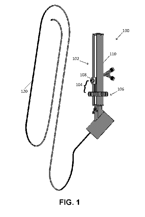
[0016] FIG. 1 is a view of the endoscopic device with tube assembly,
control
assembly, and catheter in one variation.
[0017] FIG. 2 is a view of the endoscopic device with tube assembly and
control
assembly with endoscope attachment in one variation.
[0018] FIG. 3 A is a view of the endoscopic device with tube assembly and
control
assembly without an endoscope attachment and with a Y-connector in one
variation.
[0019] FIG. 3B is a view of the tube assembly with two separated ports in
one
variation.
[0020] FIG. 4 is a view of the tube assembly in one variation.
[0021] FIG. 5A is a view of the cylindrical body in one variation.
[0022] FIG. 5B is a view of the slider mechanism in one variation.
[0023] FIG. 6A is a view of the rotation assembly in one variation.
[0024] FIG. 6B is a view of the planetary gear system in one variation.
[0025] FIG. 6C is a top view of the rotation assembly in one variation.
[0026] FIG. 6D is a view of the slider mechanism with rotational stops in
the
rotation assembly in one variation.
[0027] FIG. 7 is a view of the control assembly in one variation.
[0028] FIG. 8A is a view of the catheter in one variation.
[0029] FIG. 8B is a cross-sectional view of the catheter in one variation.
[0030] FIG. 8C is a cross-sectional view of the catheter in one variation.
[0031] FIG. 8D is a cross-sectional view of the catheter in one variation.
[0032] FIG. 8E is a cross-sectional view of the catheter in one variation.
[0033] FIG. 8F is a cross-sectional view of the catheter in one variation.
[0034] FIG. 8G depicts a catheter with a preformed distal end (i.e., tip).
[0035] FIG. 9A is a view of the slider mechanism with lumens in one
variation.
[0036] FIG. 9B is a view of the slider mechanism with lumens in one
variation.
[0037] FIG. 10A is a view of the distal tip of the catheter in one
variation.
[0038] FIG. 10B is a view of the distal tip of the catheter in one
variation.
4
CA 03125227 2021-06-25
WO 2020/146812
PCT/US2020/013205
DETAILED DESCRIPTION
[0039] The disclosure may be understood by reference to the following
detailed
description, taken in conjunction with the drawings as described below. It is
noted
that, for purposes of illustrative clarity, certain elements in various
drawings may not
be drawn to scale.
[0040] For purposes of this description, "distal" refers to the end
extending into a
body and "proximal" refers to the end extending out of the body.
[0041] For purposes of this description, "endoscopic device" refers to
medical
devices extending into the interior of a hollow organ or cavity of the body.
An
endoscopic device may be used for flexible endoscopy. In some variations, an
endoscopic device may include a mechanical manipulation controller capable of
controlling the endoscopic device with 3600 rotation and advancement and
retraction
capabilities.
[0042] A "planetary gear system", or epicyclic gear train, includes at
least two gears
arranged so that the center of one gear revolves around the center of the
other. A
carrier connects the centers of the two gears and rotates to carry the planet
gear
around the sun gear. The planet gear may rolls on the inside of the pitch
circle of a
fixed, outer ring gear, sometimes called an annular gear.
[0043] For purposes of this description "connected to" includes two
components
being directly connected or indirectly connected with intervening components.
[0044] Disclosed herein are endoscopic devices having an intuitive handle
assembly for manipulating the endoscopic device and methods of use thereof.
The
disclosed device and method for manipulation provide a simpler and more
intuitive
way of navigating the tip of a catheter associated with the endoscopic device.
For
example, the endoscopic device may provide for single handed, rotational
manipulation of the device. Also disclosed herein are endoscopic devices that
are
single use and do not require capital equipment. For example, the endoscopic
device
may include an integrated microprocessor, light source, and/or power source
which
eliminate the need for endoscopic capital equipment. In other examples, the
endoscopic device may include minimal capital equipment that is smaller and
more
portable than standard endoscopic capital equipment. The endoscopic device may
connect to or work in conjunction with another endoscope, thus allowing a
"plug-and-play" adaptation to existing endoscopes. Thus, the endoscopic device
may
be adaptable to be used with existing endoscopes without any additional
equipment.
CA 03125227 2021-06-25
WO 2020/146812
PCT/US2020/013205
[0045] As seen in FIG. 1, the endoscopic device 100 may include a tube
assembly
102 having a cylindrical body 110 and a slider mechanism 104 connected to the
cylindrical body. In a variation, the endoscopic device 100 may further
include a
control assembly attached to the cylindrical body and a catheter that extends
through
the control assembly and connects to the slider mechanism. In a variation the
tube
assembly and the control assembly may be detachably connected. In another
variation, the tube assembly and the control assembly may be integral. For
example,
the tube assembly and the control assembly may not be separated or the control
assembly may be located within the tube assembly. Catheter ports may then
fluidly
connect to the catheter and attach to the slider mechanism.
[0046] FIG. 2 illustrates one variation of the endoscopic device 100 with a
tube
assembly 102 (FIG. 4), a control assembly 116 (FIG. 7), and an endoscope
attachment 118 (FIGS. 2, 3B, and 7). The endoscope attachment 118 is
configured to
connect the endoscopic device to a larger endoscope. In one variation, the
larger
endoscope is a duodenoscope. For example, the endoscope attachment 118 may
align the entry port of the larger endoscope with the working channel of the
endoscopic device. In one variation, the endoscope attachment may be conical,
tapered, or any shape capable of connecting to an entry port of the larger
endoscope.
In some variations, the control assembly 116 is connected to an endoscope
attachment 118, as depicted in FIG. 2. In other variations, the control
assembly is not
directly connected to the tube assembly, and the endoscope attachment 118 is
directly
connected to the distal end of the cylindrical body 110 of the tube assembly
102, as
depicted in FIG. 3B. FIG. 3A illustrates a variation of the endoscopic device
100 with a
tube assembly 102 and a control assembly 116, where the control assembly does
not
include an endoscope attachment.
[0047] The endoscope attachment may be directly coupled to the entry port
of the
larger endoscope channel. The endoscope attachment may further provide a seal
at
the entry port to prevent bodily fluids leaving the endoscope and maintain
positive or
negative pressure in the lumen of the endoscope. In some variations, the
endoscope
attachment 118 may be a screw fit attachment, a snap fit attachment, a press
fit
attachment, or a compression fit attachment, without limitation.
[0048] As seen in FIGS. 3A, 3B, and 4, the tube assembly 102 includes the
cylindrical body 110 and the slider mechanism 104 (including the rotation
assembly
106 and the tip deflecting mechanism 108). The cylindrical body 110, as
further seen
6
CA 03125227 2021-06-25
WO 2020/146812
PCT/US2020/013205
in FIG. 5A, may have a proximal end and a distal end and include a plurality
of
openings 112 extending the length of the cylindrical body 110, from the
proximal end
to the distal end. In a variation, the openings may be vertical, as the
cylindrical body is
held in a vertical orientation for operation. The vertical openings may have a
90%
tolerance. In some variations, the cylindrical body may have at least 2
openings. In
some variations, the cylindrical body may have at least 3 openings. In some
variations,
the cylindrical body may have at least 4 openings. In some variations, the
cylindrical
body may have at least 5 openings. In some variations, the cylindrical body
may have
at least 6 openings. The openings may be symmetrically located around the
circumference of the cylindrical body. The number of openings and size of the
openings may correspond with the number and size of the arms used in the
planetary
gear system as discussed below. In one variation, the width of each opening is
the
diameter of at least one of the planet gears.
[0049] The slider mechanism 104, as further seen in FIGS. 5B and 7A-7C, may
include a rotation assembly 106 comprising a planetary gear system 124 and a
tip
deflecting mechanism 108. In one variation, the slider mechanism 104 includes
a
rotation assembly 106 operatively connected to a tip deflecting mechanism 108.
Referring back to FIG. 1, the slider mechanism 104 provides for a user to
manipulate
the movement of a catheter 120 operatively connected to the slider mechanism.
In
particular, the rotation assembly 106 provides for the rotation of the
catheter 120, the
tip deflecting mechanism 108 provides for the deflection of the tip of the
catheter 120,
and the entire slider mechanism 104 (the rotation assembly and the tip
deflecting
mechanism) can be translated along the cylindrical body 110 to provide for
advancement or retraction of the catheter 120. The slider mechanism 104, by
way of
the rotation assembly 106, is configured to rotate around the cylindrical body
110. This
results in rotational control of the tip of the catheter 120. The manipulation
of the
endoscopic device may be intuitive such that manipulation of the slider
mechanism
manipulates a catheter attached to the slider mechanism in a similar manner.
For
example, rotation of the rotation assembly to the right rotates the catheter
tip to the
right. Similarly, translation of the slider mechanism towards the proximal end
of the
cylindrical body retracts the catheter tip by a same or similar distance as
the
translation. Therefore, the slider mechanism allows for intuitive control of
the catheter,
including tip deflection and retraction/advancement.
[0050] The rotation assembly 106 includes, but is not limited to, a knob
122 having
7
CA 03125227 2021-06-25
WO 2020/146812
PCT/US2020/013205
an outer surface and an inner surface and a planetary gear system 124. As seen
in
FIG. 6B and 6C, the planetary gear system 124 may include a sun gear 126, at
least
two planet gears 128, and a ring gear 130, such that the planet gears 128 are
located
between the central sun gear 126 and the surrounding ring gear 130. In a
variation, the
sun gear, planet gears, and ring gear axes are coaxial. The planetary gear
system 124
may further include a carrier 132 for holding the planet gears 128. In a
variation the
carrier may have at least two arms 134 configured to hold the at least one
planet gear
128. In one variation, each arm 134 may be configured to hold two planet gears
128. In
a variation, the carrier 132 may have at least 3 arms. In a variation, the
carrier 132 may
have at least 4 arms. In a variation, the carrier 132 may have at least 5
arms. In a
variation, the carrier 132 may have at least 6 arms. The arms 134 are
symmetrical
around the sun gear and extend from the ring gear to the sun gear. In some
variations,
the planetary gear system comprises at least 2 planet gears. In some
variations, the
planetary gear system includes at least 3 planet gears. In some variations,
the
planetary gear system includes at least 4 planet gears. In some variations,
the
planetary gear system includes at least 5 planet gears. In some variations,
the
planetary gear system includes at least 6 planet gears. In some variations,
the
planetary gear system includes, at least 7 planet gears. In some variations,
the
planetary gear system includes at least 8 planet gears. In some variations,
the
planetary gear system includes at least 9 planet gears. In some variations,
the
planetary gear system includes at least 10 planet gears.
[0051] In a variation, the planetary gear system 124 is a double-pinion
planetary
gear system. In this variation, the planetary gear system includes two meshed
planet
gear sets between the sun gear and the ring gear. An arm of the carrier may
hold an
outer planet gear and an inner planet gear at different radii from the sun
gear
centerline, and allow the individual planet gears to rotate with respect to
each other.
For example, the planetary gear system in FIGS. 6A-6C includes 3 sets of
meshed
planet gear sets, each with an outer planet gear and an inner planet gear.
[0052] The size of the planetary gear system 124 may vary based on the size
of the
cylindrical body. In some variations, the size of the gears in the planetary
gear system
varies with the application of the endoscopic device. In general, the
relationship
between the gears in a double-pinion planetary gear system may be represented
by
Eqn. 1.
8
CA 03125227 2021-06-25
WO 2020/146812
PCT/US2020/013205
rr=rs+2.rpi+2.rpo, Eqn. 1
where: r, is the ring gear radius, rs is the sun gear radius, rp, is the inner
planet gear
radius, and rp0 is the outer planet gear radius. In a variation, the inner
planet gear and
the outer planet gear are the same size. In another variation, the inner
planet gear and
the outer planet gear are different sizes.
[0053] The ring gear may have a radius ranging from about 2 mm to about 20
mm.
In a variation, the ring gear may have a diameter of at least 4 mm. In a
variation, the
ring gear may have a diameter of at least 6 mm. In a variation, the ring gear
may have
a diameter of at least 10 mm. In a variation, the ring gear may have a
diameter of at
least 20 mm. In a variation, the ring gear may have a diameter of at least 30
mm. In a
variation, the ring gear may have a diameter of at least 40 mm.
[0054] In a variation, the planet gears 128 are held stationary and the
ring gear 130
is used as an input. If there is one planet gear between ring gear and the sun
gear, the
ring gear and the sun gear will rotate in opposite directions. For example, if
the ring
gear is turned clockwise, then the sun gear will turn counterclockwise. The
double-pinion planetary gear system reverses the relative rotation directions
of the
ring and sun gears. Therefore, meshed planet gear sets in the double-pinion
planetary
gear system allow the rotation of the ring gear to be in the same direction as
the
rotation of the sun gear. Therefore, when the ring gear is rotated, the sun
gear will
rotate in the same direction. In one variation, the rotation assembly includes
a
double-pinion planetary gear system such that rotation of the ring gear
results in
rotation of the sun gear, and anything attached thereto, in the same
direction. For
example, in some variations, a catheter may be attached to the sun gear so
that the
catheter is rotated based on the rotation of the ring gear. The ring gear, the
sun gear,
and the planet gears may rotate up to 360 .
[0055] In a variation, the planetary gear system 124 may rotate up to 360 .
In a
variation, the planetary gear system 124 may rotate less than 360 . In a
variation, the
planetary gear system 124 may rotate less than or equal to 180 . In a
variation, the
planetary gear system 124 may rotate less than or equal to 90 . In a
variation, the
planetary gear system 124 may rotate less than or equal to 45 . In some
examples,
the planetary gear system 124 may rotate 45 -90 , 90 -180 , or 180 -360 .
[0056] The planetary gear system may further include stops for preventing
further
rotation of the gears in one direction. This may prevent or reduce bending or
restriction
9
CA 03125227 2021-06-25
WO 2020/146812
PCT/US2020/013205
of the lumina/catheter as the rotation assembly is rotated. In some
variations, the
stops may include one or more fixed stops 133 and a rotating stop 135, for
example,
as seen in FIG. 60. When the rotating stop 135 contacts the fixed stop 133,
the
planetary gear system 124 is prevented from rotating further in that
direction. In a
variation, the planetary gear system 124 may include one stop and may rotate
up to
1800 in a single direction (ex. 180 ). In a variation, the planetary gear
system 124
may include two stops and may rotate up to 90 in a single direction (ex. 90
). In a
variation, the planetary gear system 124 may include three stops and may
rotate up to
45 in a single direction (ex. 45 ). The number of stops may depend on the
number
of pull wires included for the catheter tip deflection. For example, the
number of stops
in the planetary gear system may be less than or equal to the number of pull
wires
used for the catheter tip deflection.
[0057] The planetary gear system 124 may increase or decrease rotation from
the
knob to the catheter at a ratio ranging from 4:1 to 1:4. Using a ratio for
increased
rotation allows for smaller rotations of the knob to translate to larger
rotations of the
catheter for ease of use and minimizing movement, allowing for one hand
manipulation of the device. In a variation, the planetary gear system 124 may
increase
rotation from the knob to the catheter at a 4:1 ratio. In a variation, the
planetary gear
system 124 may increase rotation from the knob to the catheter at a 3:1 ratio
(ex. 120
of knob rotation equals 360 of catheter rotation). In a variation, the
planetary gear
system 124 may increase rotation from the knob to the catheter at a 2:1 ratio.
In a
variation, the planetary gear system 124 may match rotation from the knob to
the
catheter at a 1:1 ratio. Using a ratio for decreased rotation allows for
larger rotations of
the knob to translate to smaller rotations of the catheter for improved
resolution or
sensitivity. In a variation, the planetary gear system 124 may decrease
rotation from
the knob to the catheter at a 1:2 ratio. In a variation, the planetary gear
system 124
may decrease rotation from the knob to the catheter at a 1:3 ratio. In a
variation, the
planetary gear system 124 may decrease rotation from the knob to the catheter
at a
1:3 ratio. In a variation, the planetary gear system 124 may decrease rotation
from the
knob to the catheter at a 1:4 ratio.
[0058] In a variation, the sun gear may be located inside the cylindrical
body and
the ring gear may be located outside the cylindrical body. The arms of the
carrier may
then extend through corresponding openings in the cylindrical body to connect
the
planet gears to the sun and ring gears. This arrangement allows for the slider
CA 03125227 2021-06-25
WO 2020/146812
PCT/US2020/013205
mechanism to be pushed up and down the cylindrical body in a linear motion and
still
transfer rotary motion from the outside to the inside of the tube assembly. In
some
variations, the knob is integral with or connected to the planetary gear
system. The
inner surface of the knob may engage the planetary gear system and the outer
surface
of the knob may allow for the user to adjust or manipulate the planetary gear
system.
For example, the planetary gear system may include a ring gear on the inner
surface
of the knob, as seen in FIG. 6A and FIG. 6C. Therefore, a user may rotate the
knob to
effect rotation of the sun gear and anything attached to the sun gear, such as
a
catheter.
[0059] As seen in FIG. 6A, the outer surface of the knob 122 may include at
least
one recession 136 for receiving a finger or thumb of the user. The recession
may aid
the user in gripping the knob and the endoscopic device. The recession may
also
provide orientation for the positioning of the catheter. In other variations,
the knob
comprises a plurality of recessions on the outer surface of the knob. In some
variations, the knob may include at least 1 recession along the circumference
of the
outer surface of the knob. In a variation, the knob may include at least 2
recessions. In
a variation, the knob may include at least 3 recessions. In a variation, the
knob may
include at least 4 recessions. In a variation, the knob may include at least 5
recessions. In a variation, the knob may include at least 6 recessions. In a
variation,
the knob may include at least 10 recessions. In a variation, the knob may
include at
least 15 recessions along the circumference of the outer surface of the knob.
In one
variation, the at least one recession is about the width of an average thumb.
[0060] The slider mechanism 104 is also configured to translate toward the
distal
end or toward the proximal end of the cylindrical body 110. The translation of
the slider
mechanism provides for advancement or retraction of a catheter connected to
the
slider mechanism. The slider mechanism is able to translate along the
cylindrical body
because the openings 112 on the cylindrical body 110 extend the length of the
cylindrical body and align with the arms 134 of the carrier 132 in the
rotation assembly
106. Therefore, by way of the openings, the planet gears can engage with the
ring
gear on the inner surface of the knob while also allowing the entire slider
mechanism
to translate. In some variations, the slider mechanism may be moved along the
length
of the cylindrical body without rotating the rotation assembly. In other
variations, the
slider mechanism may be moved along the length of the cylindrical body while
rotating
the rotation assembly.
11
CA 03125227 2021-06-25
WO 2020/146812
PCT/US2020/013205
[0061] As seen in FIG. 5B, the slider mechanism 104 further includes a tip
deflecting mechanism 108. The tip deflecting mechanism 108 is operatively
connected
to the rotation mechanism 106 such that both the tip deflecting mechanism and
the
rotation mechanism translate and rotate together. The tip deflecting mechanism
allows for deflecting the distal tip of a catheter connected to the slider
mechanism. In a
variation, the tip deflecting mechanism may control a single pull wire
operably
connected to the distal tip of the catheter such that engaging the tip
deflecting
mechanism pulls the pull wire and moves or deflects the tip in a single
direction. In
another variation, the tip deflecting mechanism may control two pull wires
operably
connected to the distal tip of the catheter such that engaging the tip
deflecting
mechanism pulls a pull wire and moves or deflects the tip in up to two
directions. In
another variation, the tip deflecting mechanism may control three pull wires
operably
connected to the distal tip of the catheter such that engaging the tip
deflecting
mechanism pulls a pull wire and moves or deflects the tip in up to three
directions.
[0062] The tip deflecting mechanism may include but is not limited to a
switch, a
lever, or at least one button. In a variation, a lever tip deflecting
mechanism may have
at least a first position corresponding to the catheter tip in a straight
configuration and
a second position corresponding to the catheter tip in a deflected
configuration. In a
variation, a switch tip deflecting mechanism may have at least a first
position
corresponding to the catheter tip in a straight configuration and a second
position
corresponding to the catheter tip in a deflected configuration. In a
variation, a button tip
deflecting mechanism may have at least a first button corresponding to the
catheter tip
in a straight configuration and a second button corresponding to the catheter
tip in a
deflected configuration. In some variations, the tip deflecting mechanism may
include
at least one button, at least two buttons, or at least three buttons.
[0063] In a variation, the tip deflecting mechanism may be non-powered. For
example, the tip deflecting mechanism may be mechanically operated. The tip
deflecting mechanism may be a non-powered lever. In another variation, the tip
deflecting mechanism may be powered or motorized. For example, the tip
deflecting
mechanism may include gearing and a power source or access to a power source.
In
some examples, the power source for the motor for the tip deflecting mechanism
may
be within a control assembly, either integrated with or external to the tube
assembly. A
powered tip deflecting mechanism may provide more control and precise movement
of
the wire and therefore provide more control and precise movement of the distal
tip of
12
CA 03125227 2021-06-25
WO 2020/146812
PCT/US2020/013205
the catheter. The tip deflecting mechanism may be a powered lever, powered
switch,
or powered button. The tip deflecting mechanism may further include a sensor
configured to measure the degree of deflection of the tip of the catheter. The
sensor
may be configured to determine the location of the distal tip or how much the
distal tip
has deflected in relation to a straight configuration. For example, the sensor
may
measure the movement of gears in a powered tip deflecting mechanism that may
then
be converted to the movement of the distal tip of the catheter. In a
variation, the tube
assembly may further include an indicator operatively connected to the sensor
to
provide information on the location of the distal tip of the catheter or the
amount of
change in the deflection of the distal tip. In one variation, the indicator
may be a
display.
[0064] The endoscopic device 100 may further include a catheter 120
operatively
connected to the slider mechanism 104. In a variation, the distal end of the
catheter
may then be manipulated by operation of the slider mechanism. In a variation,
the
catheter may include at least two lumina that extend longitudinally along the
catheter.
FIG. 8A shows a portion of the catheter 120 and FIGS. 8B-8F show various
cross-sections of the catheter 120. In a variation, the catheter may include
at least
three lumina that extend longitudinally along the catheter. In a variation,
the catheter
may include at least four lumina that extend longitudinally along the
catheter. In a
variation, the catheter may include at least five lumina that extend
longitudinally along
the catheter.
[0065] Referring to FIGS. 3A and 3B, the tube assembly 102 may further
include
one or more ports fluidly connected to the catheter (not shown). The tube
assembly
102 may include at least one port, at least two ports, or at least three ports
fluidly
connected to the catheter. In some variations, the ports may be connected to
the slider
mechanism 104 such that the ports also translate when the slider mechanism 104
is
translated along the cylindrical body 110. The ports may provide access to one
or
more lumina of the catheter. In some variations, the ports may be flush ports
137
connected to one or more lumina for irrigation. The flush ports 137 may be
configured
for connecting to a source of irrigation fluid, such as saline. In some
variations, the
ports may be access ports 139 connected to one or more lumina for working
channel
access. In a variation, the tube assembly includes two flush ports. In another
variation,
the tube assembly includes a flush port 137 and a working channel access port
139. In
some examples, the tube assembly 102 may include may include two ports at the
13
CA 03125227 2021-06-25
WO 2020/146812
PCT/US2020/013205
same location on the tube assembly via a Y-connector 138, as seen in FIG. 3A,
or may
include two ports separated by a distance along the tube assembly, as seen in
FIG.
3B. FIG. 3A shows a Y-connector 138 with catheter ports for fluidly accessing
the
lumina of the catheter 120 attached to the slider mechanism 104 on the tube
assembly
102. In one variation, the Y-connector 138 and/or ports may extend though one
of the
plurality of openings on the cylindrical body 110.
[0066] As seen in FIGS.8B-8F, the lumina may be irrigation channels, pull
wire
channels, electrical channels, and/or a working channel. For example, the
catheter
120 may include at least one or at least two irrigation channels 140, at least
one
electrical channel 141, at least one working channel 142, and at least one
pull wire
channel 143. The irrigation channels 140 may be used to supply fluid to the
distal end
of the catheter. The electrical channel(s) 141 may be used to hold connections
for a
camera and/or light source at the distal end of the catheter. The working
channel may
be used to provide access to the distal end of the catheter. Therapeutic
devices,
diagnostic devices, or accessories may be passed through the working channel
for
use at the distal end of the catheter. The working channel can also be used to
aspirate
and/or flush fluid in or out of the catheter. The pull wire channels may be
used to hold
one or more pull wires for manipulating the deflection of the catheter. In a
variation, the
catheter may include at least one pull wire channel. In another variation, the
catheter
may include at least two pull wire channels. In another variation, the
catheter may
include at least three pull wire channels. When more than one pull wire
channels are
present, they may be located opposite one another and/or equidistant from one
another to allow for greater control of the deflection of the catheter tip.
[0067] As seen in FIG. 8B, in at least one variation, the catheter 120 may
include
two irrigation channels 140, two electrical channels 141, a working channel
142, and
one pull wire channel 143. As seen in FIG. 8C, in at least one variation, the
catheter
120 may include two irrigation channels 140, one electrical channel 141, a
working
channel 142, and one pull wire channel 143. In this variation, the one
electrical
channel 141 may be slotted such that it has an oval cross-sectional shape and
may be
configured to hold connections for both the camera and light source(s). As
seen in
FIG. 80, in at least one variation, the catheter 120 may include one
irrigation channel
140, one electrical channel 141, a working channel 142, and two pull wire
channels
143. In this variation, the irrigation channel 140 and the electrical channel
141 are
slotted and curved in shape. As seen in FIG. 8E, in at least one variation,
the catheter
14
CA 03125227 2021-06-25
WO 2020/146812
PCT/US2020/013205
120 may include two irrigation channels 140, two electrical channels 141, a
working
channel 142, and two pull wire channels 143. As seen in FIG. 8F, in at least
one
variation, the catheter 120 may include two irrigation channels 140, two
electrical
channels 141, a working channel 142, and three pull wire channels 143.
[0068] FIG. 8G depicts a catheter 200 with a preformed distal end (i.e.,
tip) 202. As
depicted in FIG. 8G, the distal end is preformed to be in a set position 204,
in this case
perpendicular (90 degrees) to the central axis of the catheter. With no
tension from the
pull wire, the preformed distal end 202 remains at 90 degrees. When tension is
applied
via the tip deflecting mechanism and pull wire, the distal end 202 can be
deflected in
the opposite direction, i.e. up to -90 degrees. In some variations, the distal
end 202
may be deflected up to -90 degrees in the opposite direction (position 206).
In other
variations, the distal end 202 may be defected to be in line with the central
axis of the
catheter (position 208). Using a catheter with a preformed distal end may
allow for the
distal end to deflect 90 degrees using one pull wire. It will be appreciated
that 90
degrees is only for illustration; the preformed set position can be at any
angle from 0 ¨
180 degrees.
[0069] The size and shape of the lumina in the catheter may vary depending
on
the number of lumina and the arrangement within the catheter. For example, the
lumina may have a circular, oval, square, rectangular, curved, star-shaped, or
irregular
cross-sectional shape. Different lumina for electrical channels, working
channel,
and/or irrigation channels can have different shapes or the same shapes. The
addition
of one or more pull wire channels may change the size of the electrical
channels,
working channel, and/or irrigation channels. In a variation, the working
channel may
have a diameter of greater than 1.5 mm. In a variation, the working channel
may have
a diameter of at least 1.8 mm. In a variation, the working channel may have a
diameter
of at least 1.9 mm. In a variation, the working channel may have a diameter of
at least
2 mm. For example, the working channel may be 20%-50% larger than a working
channel in a standard endoscopic device (usually 1.2 mm). In a variation, the
working
channel may be 20% larger that a working channel in a standard endoscopic
device.
In a variation, the working channel may be 30% larger that a working channel
in a
standard endoscopic device. In a variation, the working channel may be 40%
larger
that a working channel in a standard endoscopic device. In some variations,
the
endoscopic device is a cholangioscope. In a variation, the working channel may
be
50% larger that a working channel in a standard endoscopic device. In a
variation, the
CA 03125227 2021-06-25
WO 2020/146812
PCT/US2020/013205
working channel may be 60% larger that a working channel in a standard
endoscopic
device. In a variation, the working channel may be 70% larger that a working
channel
in a standard endoscopic device. A larger working channel may allow for larger
and a
wider variety of therapeutic and diagnostic devices or accessories to be
placed within
the working channel. The working channel 142 may provide for access for
therapeutic
probes at the tip of the catheter including, but not limited to forceps, laser
probes,
Electrohydraulic Lithotripsy (EHL) probes, or Radiofrequency Ablation (RFA)
probes.
In one example, the working channel of a catheter used with a cholangioscope
may be
about 50% larger than the working channel on standard cholangioscope catheters
(i.e.
SpyGlassTm). The larger working channel may have capacity for 60% larger
biopsy
forceps or provide improved suction for ductal clearance.
[0070] The catheter 120 may have an outer diameter of at least 3 mm. In a
variation, the catheter may have a diameter of at least 3.5 mm. In a
variation, the
catheter may have a diameter of at least 4 mm. In a variation, the catheter
may have a
diameter of at least 4.5 mm. In a variation, the catheter may have a diameter
of at least
mm. In other variations, the catheter size may range from about 5 French to
about 15
French. In a variation, the catheter may have a diameter of at least 5 French.
In a
variation, the catheter may have a diameter of at least 7 French. In a
variation, the
catheter may have a diameter of at least 10 French. In a variation, the
catheter may
have a diameter of at least 11 French. In a variation, the catheter may have a
diameter
of at least 13 French. In a variation, the catheter may have a diameter of at
least 15
French. In another variation, the catheter may have a diameter of less than or
equal to
French. The size of the catheter may be selected based on the use of the
endoscopic device and where it will be used in the body.
[0071] Referring to FIGS. 9A and 9B, one or more of the lumina of the
catheter
may connect to or extend through the slider mechanism 104 for connection to
the one
or more ports or the tip deflecting mechanism 108. For example, FIG. 9A shows
the
working channel 142 and a pull wire channel 142 passing through the rotation
assembly 106. In a variation, the working channel 142 may terminate in a
working
channel access port (not shown). In another variation, the pull wire channel
143 may
be connected to the tip deflecting mechanism 108 such that the pull wire in
the pull
wire channel 143 may be controlled by the tip deflecting mechanism 108. In
another
example, FIG. 9B shows an irrigation channel 140 connected to the rotation
assembly
106. In a variation, the irrigation channel 140 may terminate in a flush port
137.
16
CA 03125227 2021-06-25
WO 2020/146812
PCT/US2020/013205
[0072] Referring to FIGS. 10A and 10B, the catheter 120 may further include
a
camera 144 at the distal end of the catheter. The camera 144 may be connected
to the
tube assembly 102. In an example, the camera 144 may be connected to an
electrical
channel 141 in the catheter 120. The camera 144 may receive power and/or send
signals through the electrical channel 121. In a variation, the camera may be
a CMOS
camera. The camera may have a resolution of at least 100,000 pixels. In a
variation,
the camera may have a resolution of at least 120,000 pixels. In a variation,
the camera
may have a resolution of at least 140,000 pixels. In a variation, the camera
may have a
resolution of or at least 160,000 pixels. In a variation, the camera may have
a field of
view of at least 100 . In a variation, the camera may have a field of view of
at least
110 . In a variation, the camera may have a field of view of at least 120 .
The camera
may provide for enhanced visual inspection of benign and malignant neoplasms
and
may improve diagnostic capabilities of the endoscopic device. Better
visualization
provided by the camera in the catheter may improve therapeutic interventions
provided by the endoscopic device.
[0073] In a variation, the catheter 120 may further include a light source
146 at its
distal end to provide light for the camera 144. The catheter may include at
least one
light source or at least two light sources. In one variation, the light source
may be an
LED located at the distal end of the catheter. In another variation, the light
source 146
may be two LEDs at the distal end of the catheter, as seen in FIGS. 10A and
10B. The
LEDs may be circular or rectangular in shape and may be located on either side
of the
camera 144. In a variation, the light source may be at least one LED recessed
from the
distal end of the catheter, such that the LEDs and the camera are not located
on the
same plane. For example, the LED may be a distance from the distal end of the
catheter and the distal end of the catheter may be translucent such that the
translucent
distal end disperses the light from the LED and causes the distal end of the
catheter to
glow. In another variation, the catheter may include at least one optical
fiber that that
transmits light from a light source external to the catheter to the distal end
of the
catheter. For example, the light source may be in the control assembly or may
be
external to the endoscopic device and the light signal transmitted through an
optical
fiber.
[0074] The endoscopic device 100 may be used for flexible gastrointestinal
endoscopy. Non-limiting examples of endoscopic devices include a laryngoscope,
an
esophagoscope, esophagogastroduodenoscope, an enteroscope, a colonoscope, a
17
CA 03125227 2021-06-25
WO 2020/146812
PCT/US2020/013205
duodenoscope, a cholangioscope, a rectoscope, or a proctoscope. In one
variation,
the endoscopic device is a cholangioscope. In one example, the cholangioscope
may
be used in endoscopic retrograde cholangiopancreatography (ERCP) or
intraductal
endoscopy and cholangiopancreatography (IECP). The endoscopic device may or
may not include video imaging capabilities.
[0075] As seen in FIGS. 2 and 8, the endoscopic device 100 may further
include a
control assembly 116. In a variation, the control assembly 116 may include a
microprocessor. For example, the microprocessor may be a video processor. The
video processor may be operatively connected to the camera in the catheter.
The
video processor may be configured to process a video signal from the camera to
be
transmitted for viewing. The video signal may be transmitted to a display for
viewing
via a wire or wirelessly. In a variation, the control assembly 116 also
includes a
wireless transceiver. In some variations, the wireless transceiver may be a
WiFi or
Bluetooth transceiver. The wireless transceiver may be configured to send
and/or
receive signals, such as video signals. In other variations, the control
assembly may
include a WiFi or Bluetooth transmitter. In one variation, the wireless
transceiver may
be configured to send the video signal from the video processor to a video
display. The
transmission of the video signal may be simultaneous with the operation of the
endoscopic device, such that an operator of the endoscopic device can view the
location of the distal end of the catheter in real time. In other variations,
the video
processor may be connected to a display via a wire or cable.
[0076] In some variations, the control assembly 116 also includes a light
source.
The light signal from the light source in the control assembly may then be
transmitted
to the distal end of the catheter with optical fibers. In other variations,
the light source
may be at the distal end of the catheter or may be located external to the
endoscopic
device. In some variations, the control assembly 116 may further include a
power
source. For example, the power source may be a battery. The battery may be
disposable or rechargeable. In other variations, the control assembly may be
powered
by an external power source. For example, the control assembly may be powered
through a USB connection. The control assembly may also be connected to an
endoscope attachment 118. The endoscope attachment 118 may be configured to
fit
within a portion of the working channel of a larger endoscope
[0077] The control assembly and the tube assembly may be fluidly connected
such
that a catheter may pass through the control assembly and into the tube
assembly. In
18
CA 03125227 2021-06-25
WO 2020/146812
PCT/US2020/013205
a variation, the tube assembly 102 and the control assembly 116 may be
detachably
connected. For example, as seen in FIG. 2, the tube assembly 102 and the
control
assembly 116 may be connected with a locking mechanism 114. In this variation,
one
or both of the tube assembly and control assembly may be disposable. In
another
variation, the tube assembly and the control assembly are integrally connected
as a
single assembly. For example, the tube assembly and the control assembly may
not
be separated. In another variation, the control assembly may be located within
the
tube assembly. When the tube assembly and the control assembly are integrally
connected, the tube assembly and the control assembly are both single
use/disposable. The inclusion of the control assembly in the endoscopic device
provides for a clinician to use the device without requiring capital
equipment. For
example, the endoscopic device may include an integrated microprocessor, light
source, and or power source which eliminates the need for endoscopic capital
equipment. This may allow clinicians greater access to the endoscopic device
because they do not need to invest in capital equipment in order to operate
the
endoscopic device. Instead, all the equipment needed is included in the
endoscopic
device. Moreover, the single use aspect of the endoscopic device may prevent
contamination between patients. In another variation, the control assembly is
separate
from and external to the tube assembly. For example, the control assembly may
be
located in a separate box and may connect to the tube assembly and/or catheter
using
an accessory cable connection. The separate control assembly may be configured
for
processing/controlling a motor for tip deflection, the LEDs, and/or processing
video
and may be powered through USB or battery. In some examples, the separate
control
assembly may intercept the video signal for processing before the video signal
goes to
a monitor. The separation of the control assembly in the endoscopic device
provides
for a reduction in the size of the endoscopic device. In addition, a separate
control
assembly may be reused between patients. The separate control assembly may be
smaller than standard endoscopy capital equipment and may be easily
transported or
moved between rooms, hospitals, or locations. This may allow clinicians
greater
access to the endoscopic device because they do not need to invest in large or
expensive capital equipment in order to operate the endoscopic device.
[0078] Further
provided herein is a method of manipulating the endoscopic device
by inserting the endoscopic device with a catheter through a working channel
of an
endoscope. The method may further include rotating the rotation assembly
around the
19
CA 03125227 2021-06-25
WO 2020/146812
PCT/US2020/013205
cylindrical body to rotate the catheter of the endoscopic device. In some
variations, the
rotation assembly may rotate up to or including 3600. In some variations, the
rotational
assembly may rotate up to or including 180 . In some variations, the
rotational
assembly may rotate up to or including 90 . In some variations, the rotational
assembly may rotate up to or including 60 . This can depend on the number of
stops
and/or pull wires, which can rotate the catheter up to or including 360 .
[0079] In some variations, the rotational assembly may rotate up to or
including
200 clockwise and counterclockwise. In some variations, the rotational
assembly
may rotate up to or including 100 clockwise and counterclockwise. In some
variations, the rotational assembly may rotate up to or including 70
clockwise and
counterclockwise.
[0080] The method may further include translating the slider mechanism
toward the
distal end or toward the proximal end of the cylindrical body to extend or
retract the
catheter, respectively. The method may further include engaging a tip
deflecting
mechanism to deflect the tip of the catheter. The movement of the slider
mechanism
(rotation, advancement and/or retraction, and tip deflection) provides for
intuitive,
single handed manipulation of a catheter associated with the endoscopic device
and
provides greater control of the catheter over existing devices.
[0081] The method may further include activating a light source in the
control
assembly or at the distal tip of the catheter and acquiring a video signal
from a camera
at the distal tip of the catheter. The method may further include flushing the
distal end
of the catheter with an irrigation fluid. This may clear the area in front of
the camera to
provide a clearer video image. The method may further include processing the
video
signal from the camera with a video processor in a control assembly and
transmitting
the video signal to an external display. The video signal may be transmitted
wirelessly
using a wireless transceiver. The transmission of the video signal may allow
the user
to view the anatomy at the distal end of the catheter in real time. This may
provide
feedback for further manipulation of the catheter with the tube assembly of
the
endoscopic device.
[0082] It should be noted that the endoscopic device represents a single
variation
for endoscopy, and claimed subject matter is not limited to any particular
variation. For
example, an endoscopic device may be used in association with other endoscopic
devices or catheter manipulation mechanisms and advanced into body cavities,
including but not limited to the esophagus, colon, or biliary ducts of a human
patient,
CA 03125227 2021-06-25
WO 2020/146812
PCT/US2020/013205
animal patient. Other variations may involve the use of other types of probing
devices
that may be used to view or probe objects in internal structures of living
organisms
and/or mechanical apparatuses, and the claimed subject matter is not limited
in this
respect.
[0083] Having
described several variations, it will be recognized by those skilled in
the art that various modifications, alternative constructions, and equivalents
may be
used without departing from the spirit of the invention. Additionally, a
number of
well-known processes and elements have not been described in order to avoid
unnecessarily obscuring the present invention. Accordingly, the above
description
should not be taken as limiting the scope of the invention.
[0084] Those
skilled in the art will appreciate that the presently disclosed variations
teach by way of example and not by limitation. Therefore, the matter contained
in the
above description or shown in the accompanying drawings should be interpreted
as
illustrative and not in a limiting sense. The following claims are intended to
cover all
generic and specific features described herein, as well as all statements of
the scope
of the present method and system, which, as a matter of language, might be
said to fall
therebetween.
21