Note: Descriptions are shown in the official language in which they were submitted.
CA 03125666 2021-06-30
WO 2020/150317 PCT/US2020/013635
1
POWERED HAIR CLIPPERS WITH BLADE ASSEMBLIES INCLUDING BLADE
SUSPENSION ASSEMBLIES
CROSS-REFERENCE
[0001] This application claims the benefit of and priority to U.S.
Provisional Patent
Application No. 62/792,591, titled Powered Hair Clippers with Blade Assemblies
Including
Blade Suspension Assemblies, filed January 15, 2019, the details of which are
hereby
incorporated by reference.
TECHNICAL FIELD
[0002] The present specification generally relates to powered hair
clippers and, more
specifically, to powered hair clippers with blade assemblies including blade
suspension
assemblies that can be used to extend and retract blades based on an applied
force or lack thereof
on the blades.
BACKGROUND
[0003] Hair clippers are provided for hair removal. Some hair clippers
may be suitable
for everyday use and some hair clippers may be suitable for more specialized
uses, such as in
preparation for a medical procedure. The hair clippers generally include a
blade assembly that
includes a housing and a blade that extends outwardly from the housing. The
housing may
include a surface that glides along the skin as hair is being removed using
the blade. A user
typically applies a force against the skin during a hair removal operation.
Application of too
much force against the skin using the blade and/or operation at too steep of
an angle relative to
the skin can cause nicking of the skin.
SUMMARY
[0004] In one embodiment, a hair clipper includes a clipper body
comprising a motor
and a blade assembly connected to the clipper body such that the motor moves a
blade of the
blade assembly during operation. The blade assembly comprising a blade housing
and the blade
that extends outwardly from an opening in the housing and a linkage that is
connected to the
blade and biases the blade toward a fully extended configuration. Wherein,
upon application of
a force against the blade during use that is above a preselected threshold,
the blade assembly
CA 03125666 2021-06-30
WO 2020/150317 PCT/US2020/013635
2
includes a retracted configuration wherein the blade retracts into the blade
housing using the
linkage.
[0005] In another embodiment, a blade assembly connects to a clipper body
of a hair
clipper such that a motor moves a blade of the blade assembly during
operation. The blade
assembly includes a blade housing and the blade that extends outwardly from an
opening in the
housing and a linkage that is connected to the blade and biases the blade
toward a fully extended
configuration. Wherein, upon application of a force against the blade during
use that is above a
preselected threshold, the blade assembly includes a retracted configuration
wherein the blade
retracts into the blade housing using the linkage.
[0006] In another embodiment, a method of using a hair clipper for hair
removal from a
skin area of a patient is provided. The method includes coupling a blade
assembly to a clipper
body of the hair clipper. The blade assembly includes a blade housing and the
blade that
extends outwardly from an opening in the housing and a linkage that is
connected to the blade
and biases the blade toward a fully extended configuration. Wherein, upon
application of a
force against the blade during use that is above a preselected threshold, the
blade assembly
includes a retracted configuration wherein the blade retracts into the blade
housing using the
linkage. A guide surface of the blade assembly is faced toward the skin area.
The blade
assembly is operated to remove hair from the skin area. A blade of the blade
assembly is
retracted into the blade housing using a linkage if a force against the blade
during use is above a
preselected threshold.
[0007] These and additional features provided by the embodiments
described herein will
be more fully understood in view of the following detailed description, in
conjunction with the
drawings.
BRIEF DESCRIPTION OF THE DRAWINGS
[0008] The embodiments set forth in the drawings are illustrative and
exemplary in
nature and not intended to limit the subject matter defined by the claims. The
following detailed
description of the illustrative embodiments can be understood when read in
conjunction with the
following drawings, where like structure is indicated with like reference
numerals and in which:
[0009] FIG. 1 is a perspective view of a hair clipper with charging
station, according to
one or more embodiments shown and described herein;
CA 03125666 2021-06-30
WO 2020/150317 PCT/US2020/013635
3
[0010] FIG. 2 is a perspective, schematic view of a blade assembly for
use with the hair
clipper of FIG. 1, according to one or more embodiments shown and described
herein;
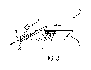
[0011] FIG. 3 is a side section view of the blade assembly of FIG. 2,
according to one or
more embodiments shown and described herein;
[0012] FIG. 4 is a side schematic section view of the blade assembly of
FIG. 3 in an
extended configuration, according to one or more embodiments shown and
described herein;
[0013] FIG. 5 is a schematic plan view of blades of the hair clipper of
FIG. 1, according
to one or more embodiments shown and described herein; and
[0014] FIG. 6 is a side schematic section view of the blade assembly of
FIG. 3 in
retracted configuration, according to one or more embodiments shown and
described herein.
DETAILED DESCRIPTION
[0015] Embodiments described herein are generally directed to powered
hair clippers
with blade assemblies including blade assemblies that are provided with a
blade suspension
assembly that allows blades to be retracted and extended depending on force
against the skin and
angle of the blades. The hair clippers include a clipper body and the blade
assembly that is
connected to a motor that is located in the blade body. The motor is used to
oscillate a first
blade of the blade assembly relative to a second blade of the blade assembly
in order to cut hair
as the blade assembly is moved across the skin. The blade assembly includes a
blade housing
that includes a guide surface that is used to guide the blade assembly along a
skin surface.
While the guide surface can help a user guide the blade assemblies, there may
be occasions
where an increased force and cutting angle are applied through the blades
against the skin. The
blade suspension assembly can retract the blades into the blade housing in
order to reduce the
force and contact with the skin depending on an amount of applied force.
[0016] Referring to FIG. 1, a hair clipper 10 includes a clipper body 12
that provides a
housing for components of the hair clipper, such as a motor (e.g., a rotary
motor), which is
illustrated schematically by element 14, and a user interface 16 that is used
to control operation
of the hair clipper 10. The clipper body 12 may further include a rechargeable
battery (e.g., a
lithium battery) that can be recharged using a charging station 18.
CA 03125666 2021-06-30
WO 2020/150317 PCT/US2020/013635
4
[0017] A blade assembly 20 is connected to the clipper body 12. The blade
assembly 20
includes a blade housing 22 and a first blade 24 that extends outwardly from
the blade housing
22. In some embodiments, the blade assembly 20 may be removable from the
clipper body 12
and be disposable. In other embodiments, the blade assembly 20 may be a
permanent part of the
clipper body 12 and may not be intended to be removable without damage to the
hair clipper 10.
For removable blade assemblies 20, there may different blade assembly types,
such as general
purpose blade assembly for body hair, a neuro blade assembly for scalp and
other thick, course
hair and a sensitive blade assembly for perineal/sensitive areas. The blade
assemblies may be
intended for a single use.
[0018] The blade assembly 20 includes the first blade 24 and a second
blade 26 that both
extend outwardly from a corner of the blade housing 22 defining a blade
cutting direction in the
direction of arrow 30. The blades 24 and 26 have teeth that provide a comb-
like shape across a
width of the blades 24 and 26 defining a width direction in the direction of
arrow 32 that is
perpendicular to the blade cutting direction. The motor 14 reciprocates the
first blade 24 in the
width direction relative to the second blade 26 via a linkage 34 in order to
cut hair located
between the teeth.
[0019] The blade housing 22 includes a guide surface 36 that is located
at a skin
engagement end 37 of the hair clipper 10. The guide surface 36 faces the skin
during a trimming
operation. As can be seen, the guide surface 36 defines a plane that is
substantially parallel with
the cutting direction 30. In some embodiments, the cutting direction 30 and
the guide surface 36
may be at an angle (e.g., between about 135 and about 145 degrees) that is
oblique to a central
axis that passes through a base portion 38 of the blade housing 22 (FIG. 4).
[0020] Referring to FIG. 2, a schematic illustration of a body attachment
side 40 of the
blade assembly 20 is illustrated. The blade assembly 20 includes the first
blade 24 and the
second blade 26. The first blade 24 is connected to a guide plate 42 that
connects to the linkage
34 (e.g., an eccentric shaft) that is rotated by the motor 14 to move the
first blade 24 in the width
direction. In this regard, the first blade 24 may be referred to as a moveable
blade that moves in
the widthwise direction relative to the second blade.
[0021] Both blades 24 and 26 ate connected to a linkage 44. The linkage
44 may include
a pivot arm 46 that is connected to the blades 24 and 26. The pivot arm 46 can
pivot about pivot
axis A to allow for movement of the blades 24 and 26 into and out of the blade
housing 22. A
biasing member 48, such as a spring, may be provided that biases the pivot arm
46 and the
CA 03125666 2021-06-30
WO 2020/150317 PCT/US2020/013635
blades 24 and 26 toward a fully extended position. Upon an application of
force beyond a
predetermined amount (e.g., at least about 3.5 N), the biasing force of the
biasing member 48
may be overcome, thereby causing the blades 24 and 26 to retract into the
housing body 22, as
represented by FIGS. 3-5. A skin contact angle 0 (e.g., of between about 15
and about 45
degrees) may also affect whether the blades 24 and 26 retract from the fully
extended position.
The blades 24 and 26 may retract only partially or fully into the blade
housing 22 depending on
the force against the blades 24 and 26 and the skin contact angle 0.
[0022] A method of using the hair clipper for hair removal from a skin
area of a patient
may include coupling the blade assembly 20 to the clipper body 12 of the
surgical clipper 10.
The blade assembly 20 includes the blades 24 and 26 that have a fully extended
configuration
where an end of the blades 24 and 26 is located outside the blade housing 22
and a fully
retracted configuration where the end of the blades is retracted inside the
blade housing 22. The
amount of blade retraction may depend on one or both of the force against the
blades 24 and 26
and the skin contact angle 0. The blades 24 and 26 may return to their
original, fully extended
configuration once the force is removed and the contact angle 0 is reduced.
[0023] As described herein, the body 12 of the surgical clipper 10 is
configured to
electronically operate the blade 24. The body 12 includes the enclosure
housing an electrical
motor and a battery, which battery is configured to be rechargeable through
coupling of the body
12 to a charging adaptor 18. The body 12 of the surgical clipper 10 further
may include a charge
indicator configured to indicate a low battery level of the battery below a
predefined threshold.
The method may include triggering an alarm through the charge indicator of the
low battery
level, coupling the body to the charging adaptor, and recharging the battery.
The alarm may be a
visual, audio, or tactile alarm. Such a visual alarm may be an LED light that
may, for example,
red to indicate the low battery level.
[0024] Embodiments can be described with reference to the following
numbered clauses,
with preferred features laid out in the dependent clauses:
[0025] Clause 1. A hair clipper comprising: a clipper body comprising
a motor; and
a blade assembly connected to the clipper body such that the motor moves a
blade of the blade
assembly during operation, the blade assembly comprising a blade housing and
the blade that
extends outwardly from an opening in the housing and a linkage that is
connected to the blade
and biases the blade toward a fully extended configuration; wherein, upon
application of a force
CA 03125666 2021-06-30
WO 2020/150317 PCT/US2020/013635
6
against the blade during use that is above a preselected threshold, the blade
assembly comprising
a retracted configuration wherein the blade retracts into the blade housing
using the linkage.
[0026] Clause 2. The hair clipper of clause 1 further comprising a
spring that biases
the linkage and the blade toward the fully extended configuration.
[0027] Clause 3. The hair clipper of clause 1 or 2, wherein the blade
is a first blade,
the blade assembly comprising a second blade, the motor moving the first blade
relative to the
second blade in a width direction.
[0028] Clause 4. The hair clipper of clause 1-3, wherein the blade
assembly is
removably attached to the clipper body.
[0029] Clause 5. The hair clipper of clause 1-4, wherein the linkage
comprises a
pivot arm that is connected to the blade.
[0030] Clause 6. The hair clipper of clause 5, wherein the pivot arm
is spring biased
toward the fully extended configuration.
[0031] Clause 7. The hair clipper of clause 1-6, wherein the blade
retracts into the
blade housing in a cutting direction.
[0032] Clause 8. The hair clipper of clause 1-7, wherein the blade
retracts into the
blade housing at a cutting angle that is greater than 15 degrees from a skin
surface.
[0033] Clause 9. A blade assembly that connects to a clipper body of a
hair clipper
such that a motor moves a blade of the blade assembly during operation, the
blade assembly
comprising: a blade housing and the blade that extends outwardly from an
opening in the
housing and a linkage that is connected to the blade and biases the blade
toward a fully extended
configuration; wherein, upon application of a force against the blade during
use that is above a
preselected threshold, the blade assembly comprising a retracted configuration
wherein the blade
retracts into the blade housing using the linkage.
[0034] Clause 10. The blade assembly of clause 9 further comprising a
spring that
biases the linkage and the blade toward the fully extended configuration.
[0035] Clause 11. The blade assembly of clause 9 or 10, wherein the
blade is a first
blade, the blade assembly comprising a second blade, the motor moving the
first blade relative
to the second blade in a width direction.
CA 03125666 2021-06-30
WO 2020/150317 PCT/US2020/013635
7
[0036] Clause 12. The blade assembly of clause 9-11, wherein the blade
assembly is
removably attached to the clipper body.
[0037] Clause 13. The blade assembly of clause 9-12, wherein the
linkage comprises
a pivot arm that is connected to the blade.
[0038] Clause 14. The blade assembly of clause 13, wherein the pivot
arm is spring
biased toward the fully extended configuration.
[0039] Clause 15. The blade assembly of clause 9-14, wherein the blade
retracts into
the blade housing in a cutting direction.
[0040] Clause 16. The blade assembly of clause 9-15, wherein the blade
retracts into
the blade housing at a cutting angle that is greater than 15 degrees from a
skin surface.
[0041] Clause 17. A method of using a hair clipper for hair removal
from a skin area
of a patient, the method comprising: coupling a blade assembly to a clipper
body of the hair
clipper, the blade assembly comprising: a blade housing and the blade that
extends outwardly
from an opening in the housing and a linkage that is connected to the blade
and biases the blade
toward a fully extended configuration; wherein, upon application of a force
against the blade
during use that is above a preselected threshold, the blade assembly
comprising a retracted
configuration wherein the blade retracts into the blade housing using the
linkage; facing a guide
surface of the blade assembly toward the skin area; operating the blade
assembly to remove hair
from the skin area; and retracting a blade of the blade assembly into the
blade housing using a
linkage if a force against the blade during use is above a preselected
threshold.
[0042] Clause 18. The method of clause 17 further comprising a spring
that biases
the linkage and the blade toward the fully extended configuration.
[0043] Clause 19. The method of clause 17 or 18, wherein the blade is
a first blade,
the blade assembly comprising a second blade, the motor moving the first blade
relative to the
second blade in a width direction.
[0044] Clause 20. The method of clause 17-19, wherein the blade
assembly is
removably attached to the clipper body.
[0045] For the purposes of describing and defining the present
disclosure, it is noted that
recitations herein of "at least one" component, element, etc., should not be
used to create an
CA 03125666 2021-06-30
WO 2020/150317 PCT/US2020/013635
8
inference that the alternative use of the articles "a" or "an" should be
limited to a single
component, element, etc.
[0046] It is noted that recitations herein of a component of the present
disclosure being
"configured" in a particular way, to embody a particular property, or to
function in a particular
manner, are structural recitations, as opposed to recitations of intended use.
More specifically,
the references herein to the manner in which a component is "configured"
denotes an existing
physical condition of the component and, as such, is to be taken as a definite
recitation of the
structural characteristics of the component.
[0047] For the purposes of describing and defining the present disclosure
it is noted that
the terms "substantially" and "approximately" and "about" are utilized herein
to represent the
inherent degree of uncertainty that may be attributed to any quantitative
comparison, value,
measurement, or other representation. The terms "substantially" and
"approximately" and
"about" are also utilized herein to represent the degree by which a
quantitative representation
may vary from a stated reference without resulting in a change in the basic
function of the
subject matter at issue.
[0048] Having described the subject matter of the present disclosure in
detail and by
reference to specific embodiments thereof, it is noted that the various
details disclosed herein
should not be taken to imply that these details relate to elements that are
essential components of
the various embodiments described herein, even in cases where a particular
element is illustrated
in each of the drawings that accompany the present description. Further, it
will be apparent that
modifications and variations are possible without departing from the scope of
the present
disclosure, including, but not limited to, embodiments defined in the appended
claims. More
specifically, although some aspects of the present disclosure are identified
herein as preferred or
particularly advantageous, it is contemplated that the present disclosure is
not necessarily limited
to these aspects.
[0049] It is noted that one or more of the following claims utilize the
term "wherein" as
a transitional phrase. For the purposes of defining the present disclosure, it
is noted that this
term is introduced in the claims as an open-ended transitional phrase that is
used to introduce a
recitation of a series of characteristics of the structure and should be
interpreted in like manner
as the more commonly used open-ended preamble term "comprising."