Note: Descriptions are shown in the official language in which they were submitted.
CA 03125851 2021-07-06
1
DESCRIPTION
Title: Method for Manufacturing an Aluminum Alloy Part
TECHNICAL FIELD
The technical field of the invention is a method for manufacturing a part made
of an aluminum
alloy, implementing an additive manufacturing technique.
PRIOR ART
Since the 80s, additive manufacturing techniques have been developed. These
consist in
shaping a part by addition of matter, which is in contrast with machining
techniques, aiming to
remove the matter. Formerly restricted to prototyping, additive manufacturing
is now
operational for manufacturing industrial products in mass production,
including metallic parts.
The term "additive manufacturing" is defined according to the French standard
P E67-001 as a
"set of processes allowing manufacturing, layer after layer, by addition of
matter, a physical
object based on a digital object". The standard ASTM F2792 (January 2012)
defines additive
manufacturing too. Different additive manufacturing approaches are also
defined and
described in the standard ISO/ASTM 17296-1. Resort to an additive manufacture
to make an
aluminum part, with low porosity, has been described in the document
W02015006447. In
general, the application of successive layers is carried out by application of
a so-called filler
material, and then melting or sintering of the filler material using an energy
source such as a
laser beam, an electron beam, a plasma torch or an electric arc. Regardless of
the additive
manufacturing approach that is applied, the thickness of each added layer is
in the range of a
few tens or hundreds of microns.
Other additive manufacturing methods may be used. Mention may be made for
example, and
without limitation, of melting or sintering of a filler material in the form
of a powder. This may
consist of laser melting or sintering. The patent application U520170016096
describes a
method for manufacturing a part by local melting obtained by exposure of a
powder to an
energy beam such as an electron beam or a laser beam, the method being also
referred to by
the acronyms SLM, standing for "Selective Laser Melting" or "[BM", standing
for "Electron
Beam Melting".
The mechanical properties of the aluminum parts obtained by additive
manufacturing depend
on the alloy forming the filler metal, and more specifically on its
composition as well as on the
heat treatments applied following the implementation of the additive
manufacture.
Date Recue/Date Received 2021-07-06
CA 03125851 2021-07-06
2
The Applicant has determined an alloy composition which, when used in an
additive
manufacturing method, allows obtaining parts with remarkable mechanical
performances, yet
without it being necessary to implement heat treatments such as dissolution
and quenching. In
addition, the used parts feature interesting thermal conductivity or
electrical conductivity
properties. This allows diversifying the possible applications of these parts.
DISCLOSURE OF THE INVENTION
A first object of the invention is a method for manufacturing a part including
a formation of
successive metallic layers, superimposed on one another, each layer being
formed by the
deposition of a filler metal, the filler metal being subjected to an energy
input so as to melt
and constitute, when solidifying, said layer, the method being characterized
in that the filler
metal is an aluminum alloy including the following alloy elements (weight%):
- Zr: 0.5 % to 2.5 %, preferably according to a first variant 0.8 to 2.5 %,
more preferably 1
to 2.5 %, still more preferably 1.3 to 2.5 %.; or preferably according to a
second variant
0.5 to 2 %, more preferably 0.6 to 1.8 %, more preferably 0.6 to 1.6 %, more
preferably
0.7 to 1.5 %, more preferably 0.8 to 1.5 %, more preferably 0.9 to 1.5 %,
still more
preferably 1 to 1.4 %;
- Fe: 0% to 3 %, preferably 0.5 % to 2.5 %; preferably according to a first
variant 0.8 to 2.5
%, preferably 0.8 to 2 %, more preferably 0.8 to 1.2; or preferably according
to a second
variant 1.5 to 2.5 %, preferably 1.6 to 2.4 %, more preferably 1.7 to 2.3 %;
- optionally Si: 0,3 %, preferably 0.2 %, more preferably 0.1 %;
- optionally Cu: 0.5 %, preferably 0.05 to 0.5 %, preferably 0.1 to 0.4%;
- optionally Mg: 0.2 %, preferably 0.1 %, preferably < 0.05 %;
- Other alloy elements < 0.1% individually, and < 0.5 % all in all;
- impurities: < 0.05 % individually, and < 0.15 % all in all;
the remainder consisting of aluminum.
Among the other alloy elements, mention may be made for example of Cr, V, Ti,
Mn, Mo, W,
Nb, Ta, Sc, Ni, Zn, Hf, Nd, Ce, Co, La, Ag, Li, Y, Yb, Er, Sn, In, Sb, Sr, Ba,
Bi, Ca, P, B and/or a
mischmetal.
Preferably, the method may include the following features, considered
separately or according
to technically feasible combinations:
Date Recue/Date Received 2021-07-06
CA 03125851 2021-07-06
3
- Zr: 0.8 to 2.5 %, or preferably 1% to 2.5 %, or still preferably 1.2 % to
2.5 %, or still
preferably 1.3 % to 2.5 % or still preferably 1.5 % to 2.5 %;
- Zr: 0.5 to 2 %, more preferably 0.6 to 1.8 %, more preferably 0.6 to 1.6
%, more
preferably 0.7 to 1.5 %, more preferably 0.8 to 1.5 % more preferably 0.9 to
1.5 %, still
more preferably 1 to 1.4%;
- Fe: 0.5 % to 2.5 % or 0.5 % to 2 %; preferably 0.8 to 2.5 %, preferably
0.8 to 2 %, more
preferably 0.8 to 1.2;
- Fe: 0.5 % to 2.5 % or 0.5 % to 2 %; preferably 1.5 to 2.5 %, preferably
1.6 to 2.4 %,
more preferably 1.7 to 2.3 %;
- Si: < 0.2 % and preferably < 0.1 %;
- Si 0.01 %, or optionally 0.05 %;
- Cu: 0.05 % to 0.5 %, preferably 0.1 to 0.4%;
- Zr: 0.5 % to 2.5 % and Fe 1%;
- Zr: 0.5 % to 2.5 % and Fe < 1%;
- the weight fraction of each other alloy element is strictly lower than
500 ppm, 300 pm,
200 ppm, or optionally 100 ppm;
- the weight fraction of each impurity is strictly lower than 300 pm, 200
ppm, or
optionally 100 ppm;
- the alloy includes no Cr, V, Mn, Ti, Mo, or according to a weight
fraction lower than
500 ppm, 300 ppm, 200 ppm or optionally lower than 100 ppm.
According to one variant, the used alloy according to the present invention
comprises Cu,
according to a weight fraction from 0.05 % to 0.5 %, preferably from 0.1 to
0.4 %.
In particular, each layer may feature a pattern defined from a digital model.
The method may include, following the formation of the layers, that is to say
following the
formation of the final part, an application of at least one heat treatment.
The heat treatment
may consist of or include tempering or annealing. It may also include
dissolution and
quenching, even they it is preferred to avoid these. It may also include hot
isostatic pressing.
In order to enhance mechanical properties, the heat treatment may be
performed:
- at a temperature higher than 400 C, in which case the duration of the
heat treatment is
comprised from 0.1 h to 10 h;
- or at a temperature comprised from 300 C to 400 C, in which case the
duration of the
heat treatment is comprised from 0.5 h to 100 h.
Date Recue/Date Received 2021-07-06
CA 03125851 2021-07-06
4
In order to promote the thermal or electrical conduction properties, the heat
treatment may
be performed at a temperature higher than or equal to 350 C, or higher than or
equal to
400 C, or a duration from 90 to 200 h, so as to obtain an optimum thermal or
electrical
conductivity. For example, a temperature from 380 to 470 C and a duration from
90 to 110 h.
According to an advantageous embodiment, the method includes no quenching
following the
formation of the layers, that is to say following the formation of the final
part, or following the
heat treatment. Thus, preferably, the method does not include any steps of
dissolution
followed by quenching.
According to one embodiment, the filler metal is in the form of a powder,
whose exposure to a
beam of light or of charged particles, results in a local melting followed by
a solidification, so as
to form a solid layer. According to another embodiment, the filler metal is
derived from a filler
wire, whose exposure to an electric arc results in a local melting followed by
a solidification, so
as to form a solid layer.
A second object of the invention is a metallic part, obtained after
application of a method
according to the first object of the invention.
A third object of the invention is a a filler material, in particular a filler
wire or a powder,
intended to be used as a filler material of an additive manufacturing method,
characterized in
that it is constituted by an aluminum alloy, including the following alloy
elements (weight%):
- Zr: 0.5 % to 2.5 %, preferably according to a first variant 0.8 to 2.5 %,
more preferably 1
to 2.5 %, still more preferably 1.3 to 2.5 %.; or preferably according to a
second variant
0.5 to 2 %, more preferably 0.6 to 1.8 %, more preferably 0.6 to 1.6 %, more
preferably
0.7 to 1.5 %, more preferably 0.8 to 1.5 %, more preferably 0.9 to 1.5 %,
still more
preferably 1 to 1.4 %;
- Fe: 0% to 3 %, preferably 0.5 % to 2.5 %; preferably according to a first
variant 0.8 to 2.5
%, preferably 0.8 to 2 %, more preferably 0.8 to 1.2; or preferably according
to a second
variant 1.5 to 2.5 %, preferably 1.6 to 2.4 %, more preferably 1.7 to 2.3 %;
- optionally Si: 0,3 %, preferably 0.2 %, more preferably 0.1 %;
- optionally Cu: 0.5 %, preferably 0.05 to 0.5 %, preferably 0.1 to 0.4%;
- optionally Mg: 0.2 %, preferably 0.1 %, preferably < 0.05 %;
- Other alloy elements < 0.1 % individually, and < 0.5 % all in all;
- impurities: < 0.05 % individually, and < 0.15 % all in all;
the remainder consisting of aluminum.
Date Recue/Date Received 2021-07-06
CA 03125851 2021-07-06
The aluminum alloy forming the filler material may feature the characteristics
described in
connection with the first object of the invention.
The filler material may be in the form of a powder. The powder may be such
that at least 80%
of the particles composing the powder have an average size within the
following range: 51..tm
5 to 100 p.m, preferably from 5 to 25 p.m, or from 20 to 60 p.m.
When the filler material is in the form of a wire, the diameter of the wire
may in particular be
comprised from 0.5 mm to 3 mm, and preferably comprised from 0.5 mm to 2 mm,
and still
preferably comprised from 1 mm to 2 mm.
Another object of the invention is the use of a powder or of a filler wire as
described
hereinbefore and in the rest of the description in a manufacturing method
selected amongst:
cold spray consolidation (CSC), laser metal deposition (LMD), additive
friction stir (AFS), spark
plasma sintering (FAST) or rotary friction welding (IRFW), preferably cold
spray consolidation
(CSC).
Other advantages and features will appear more clearly from the following
description of
particular embodiments of the invention, provided as non-limiting examples,
and represented
in the figures listed hereinbelow.
FIGURES
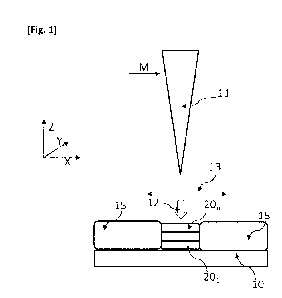
[Fig. 1] Figure 1 is a diagram illustrating a SLM-type additive manufacturing
method.
[Fig. 2] Figure 2 illustrates tensile and electrical conduction properties
determined throughout
experimental tests of Example 1, from samples manufactured by implementing an
additive
manufacturing method according to the invention.
[Fig. 3] Figure 3 is a diagram illustrating a WAAM-type additive manufacturing
method.
[Fig. 4] Figure 4 is a diagram of the specimen used according to the examples.
[Fig. 5] Figure 5 is a diagram of the second testing parts of Example 1.
[Fig. 6] Figure 6 illustrates tensile and electrical conduction properties
determined throughout
experimental tests of Example 2, from samples manufactured by implementing an
additive
manufacturing method according to the invention.
DISCLOSURE OF PARTICULAR EMBODIMENTS
Unless stated otherwise, in the description:
- the designation of the aluminum alloys is compliant with the nomenclature
of The
Aluminum Association;
Date Recue/Date Received 2021-07-06
CA 03125851 2021-07-06
6
- the contents of the chemical elements are reported in % and
represent weight
fractions. The x % - y % notation means higher than or equal to x % and lower
than or
equal to y %.
By impurities, it should be understood chemical elements that are
unintentionally present in
the alloy.
Figure 1 schematizes the operation of a Selective Laser Melting (SLM) type
additive
manufacturing method. The filler metal 15 is in the form of a powder disposed
on a support
10. An energy source, in this instance a laser source 11, emits a laser beam
12. The laser source
is coupled to the filler material by an optical system 13, whose movement is
determined
according to a digital model M. The laser beam 12 propagates according to an
axis of
propagation Z, and follows a movement according to a plane XY, describing a
pattern
depending on the digital model. For example, the plane is perpendicular to the
axis of
propagation Z. The interaction of the laser beam 12 with the powder 15 causes
a selective
melting of the latter, followed by a solidification, resulting in the
formation of a layer 201...20,.
Once a layer has been formed, it is covered with powder 15 of the filler metal
and another
layer is formed, superimposed on the layer made before. For example, the
thickness of the
powder forming a layer may be comprised from 10 to 200 p.m.
For aluminum alloys, the support 10 or tray may be heated up to a temperature
ranging up to
350 C. In general, machines that are currently available on the market enable
heating of the
tray up to 200 C. For example, the heating temperature of the tray may be
about 50 C, 100 C,
150 C or 200 C. In general, heating of the tray allows reducing the humidity
at the powder bed
and also reducing the residual stresses on the parts being manufactured. The
humidity level at
the powder bed seems to have a direct effect on the porosity of the final
part. Indeed, it seems
that the higher the humidity of the powder, the higher will be the porosity of
the final part. It
should be noted that heating of the tray is one of the existing possibilities
to carry out a hot
additive manufacturing. However, the present invention should not be limited
to the use of
this heating means alone. All other heating means may be used in the context
of the present
invention to heat up and monitor the temperature, for example an infrared
lamp. Thus, the
method according to the present invention may be carried out at a temperature
ranging up to
350 C.
Date Recue/Date Received 2021-07-06
CA 03125851 2021-07-06
7
The powder may have at least one of the following characteristics:
- Average particle size from 5 to 100 p.m, preferably from 5 to 25 p.m, or
from 20 to 60
p.m. The given values mean that at least 80 % of the particles have an average
size
within the specified range.
- Spherical shape. For example, the sphericity of a powder may be
determined using a
morphogranulometer.
- Good castability. For example, the castability of a powder may be
determined
according to the standard ASTM B213 or the standard ISO 4490 :2018. According
to
the standard ISO 4490 :2018, the flow time is preferably shorter than 50.
- Low porosity, preferably from 0 to 5 %, more preferably from 0 to 2 %,
still more
preferably from 0 to 1 % by volume. In particular, the porosity may be
determined by
analysis of images from optical micrographs or by helium pycnometry (cf. the
standard
ASTM B923).
- Absence or small amount (less than 10%, preferably less than 5 % by
volume) of small
particles (1 to 20 % of the average size of the powder), called satellites,
which stick to
the larger particles.
The implementation of such a method enables the manufacture of parts at a high
yield, which
may reach or optionally exceed 40 cm3/h.
Moreover, the Applicant has observed that the application of quenching-type
heat treatments
could induce a distortion of the part, because of the abrupt variation of
temperature. In
general, the distortion of the part is even more significant as its dimensions
are large. Yet, the
advantage of an additive manufacturing method is precisely to obtain a part
whose shape,
after manufacture, is permanent, or almost-permanent. Hence, the occurrence of
a significant
deformation resulting from a heat treatment shall be avoided. By almost-
permanent, it should
be understood that a finish machining might be performed on the part after
manufacture
thereof: the part manufactured by additive manufacturing extends according to
its permanent
shape, prior to finish machining.
After having noticed the foregoing, the Applicant has looked for an alloy
composition, forming
the filler material, allowing obtaining acceptable mechanical properties,
without requiring the
application of heat treatments, subsequent to the formation of the layers,
that is to say after
the formation of the final part, which might induce a distortion. In
particular, the aim is to
avoid heat treatments involving an abrupt variation of the temperature. Thus,
the invention
allows obtaining, by additive manufacturing, a part whose mechanical
properties are
Date Recue/Date Received 2021-07-06
CA 03125851 2021-07-06
8
satisfactory, in particular in terms of yield strength. Depending on the
selected additive
manufacturing method type, the filler material may be in the form of a wire or
a powder.
The Applicant has noticed that by limiting the number of elements present in
the alloy having a
content above 1 weight%, a good trade-off between the interesting mechanical
and thermal
properties is obtained. It is commonly recognized that the addition of
elements in the alloy
allows improving some mechanical properties of the part made by additive
manufacturing. By
mechanical properties, it should be understood for example the yield strength
and the
elongation at break. However, the addition of a too large amount, or of a too
wide variety, of
alloy chemical elements could alter the thermal conduction properties of the
part resulting
from the additive manufacture. Thus, resorting to binary or ternary alloys, in
an additive
manufacturing method, constitutes a promising way in the additive
manufacturing field.
The Applicant has considered it useful to reach a compromise between the
number and the
amount of elements added in the alloy, so as to obtain acceptable mechanical
and thermal (or
electrical) properties.
The Applicant considers that such a compromise is obtained by limiting to one
or two the
number of chemical elements forming the aluminum alloy having a weight
fraction higher than
or equal to 1 %. Thus, a particularly interesting alloy may be obtained by
adding, according to a
weight fraction higher than 1 %:
- only Zr, in which case the alloy is essentially constituted by two
elements (Al and Zr).
For example Zr: 0.5% to 2.5 % and Fe < 1%;
- only Zr and Fe, in which case the alloy is essentially constituted by
three elements (Al,
Zr and Fe). The presence of Fe in the alloy allows improving the mechanical
properties,
whether these consist of hot or cold tensile mechanical properties or
hardness. For
example Zr: 0.5 % to 2.5 % and Fe 1 %;
The presence of Zr in the alloy confers a good processability of the alloy,
the term
processability qualifying the ability of an alloy to be shaped by an additive
manufacturing
method. This is reflected, at the level of a part manufactured by additive
manufacturing, by a
virtual absence of crack-type defects, and by a low porosity. The Applicant
has noticed that a
weight fraction of Zr higher than 0.5 % confers a good processability. An
optimum weight
fraction of Zr may be comprised according to a first variant from 0.8 to 2.5%,
more preferably
1 to 2.5 %, still more preferably 1.3 to 2.5 %.; or preferably according to a
second variant from
0.5 to 2 %, more preferably from 0.6 to 1.8 %, more preferably from 0.6 to 1.6
%, more
preferably from 0.7 to 1.5 %, more preferably from 0.8 to 1.5 %, more
preferably from 0.9 to
Date Recue/Date Received 2021-07-06
CA 03125851 2021-07-06
9
1.5 %, still more preferably 1 to 1.4%. When Zr is lower than 0.5 %, the
mechanical properties
are not sufficient in general.
The Applicant has observed in a SLM process and in the presence of Zr, in
particular for a Zr
content > 0.5 %, during the solidification of each layer, equiaxed grains
forming at the bottom
of the lasing bead from primary A13Z precipitates which form in the liquid.
The primary A13Z
precipitates serve as germs, from which aluminum equiaxed grains form. The
rest of the lasing
bead solidifies in the form of columnar grains which grow radially from the
edge towards the
center of the bead. The higher the Zr content, the greater will be the
fraction of equiaxed
grains and the lower will be the fraction of columnar grains. The presence of
a sufficient
fraction of equiaxed grains is beneficial to avoid crackings at the end of
solidification.
However, when the Zr content is < 0.5 %, the concentration of primary A13Z
precipitates is too
low, which leads to a formation of coarse columnar grains which could cross
several layers,
according to an epitaxial growth, progressing from one layer to another layer.
Thus, the
obtained part is more sensitive to solidification cracking.
This effect of the Zr content on the sensitivity to cracking is specific to
additive manufacturing
methods with melting of each layer like the SLM method. In the case of a non-
additive process
like conventional so-called rapid solidification processes with compaction and
spinning of parts
from rapidly solidified thin bands or from powder, parts made of alloys with
Zr contents < 0.5
% could be manufactured without cracking. Indeed, these processes do not
require melting
during the shaping step and therefore are not subject to solidification
cracks.
The Applicant has also noticed that the presence of copper, 0,5 %, preferably
0.05 to 0.5 %,
preferably 0.1 to 0.4%, allows improving the mechanical properties and the
electrical
conductivity/yield strength trade-off after heat treatment.
Preferably, the weight fraction of Zr is comprised from 0.5 % to 2.5 %,
preferably according to
a first variant from 0.8 % to 2.5 %, or optionally from 1 % to 2.5 %, or
optionally from 1.2 % to
2.5 %, or optionally from 1.3 % to 2.5 %, or optionally from 1.5 % to 2.5 %;
or preferably
according to a second variant from 0.5 to 2 %, or optionally from 0.6 to 1.8
%, or optionally
from 0.6 to 1.6 %, or optionally from 0.7 to 1.5 %, or optionally from 0.8 to
1.5 % or optionally
from 0.9 to 1.5 %, or optionally from 1 to 1.4 %.
When the alloy includes Fe, the weight fraction of Fe is lower than or equal
to 3 %. Preferably,
it is comprised from 0.5 % to 3 %; preferably according to a first variant 0.8
to 2.5 %, preferably
0.8 to 2 %, more preferably 0.8 to 1.2; or preferably according to a second
variant 1.5 to 2.5 %,
Date Recue/Date Received 2021-07-06
CA 03125851 2021-07-06
preferably 1.6 to 2.4 %, more preferably 1.7 to 2.3 %. An association of Zr
and Fe is particularly
advantageous, as mentioned before, and confirmed by experimental tests.
The alloy may also include other alloy elements, such as Cr, V, Ti, Mn, Mo, W,
Nb, Ta, Sc, Ni, Zn,
Hf, Nd, Ce, Co, La, Ag, Li, Y, Yb, Er, Sn, In, Sb, Sr, Ba, Bi, Ca, P, B and/or
a mischmetal, according
5 to a weight fraction individually strictly lower than 0.1 % preferably
lower than 500 ppm, and
preferably lower than 300 ppm, or 200 ppm, or 100 ppm. However, some of these
alloy
elements, in particular Cr, V, Ti and Mo degrade conductivity. Cu is
considered to be less
detrimental to thermal and/or electrical conductivity.
The addition of Mg in the absence of a dissolution-quenching-tempering
treatment, would
10 lower the electrical or thermal conductivity without any significant
impact on the mechanical
properties. To that one should add its tendency to evaporate during the
atomization and SLM
process, especially for high-liquidus alloys like those tested according to
the present invention.
According to one variant, the alloy used according to the present invention
comprises no Mg
or in an impurity quantity, namely < 0,05 %.
When the alloy comprises other alloy elements, like Y, Yb, Er, Sn, In, Sb,
these are preferably
present according to a weight fraction strictly lower than 500 ppm, or
optionally strictly lower
than 300 ppm, or optionally strictly lower than 200 ppm or 100 ppm.
It should be noted that, preferably, the alloys according to the present
invention are not
AA6xxx type alloys, because of the absence of a simultaneous addition of Si
and Mg in
amounts larger than 0.2 %.
As examples, the aluminum alloy used according to the present invention may
comprise:
- Zr 1.52 %; Fe 213 ppm; Si 183 ppm; impurities: < 0.05 % each with
cumulated
impurities < 0.15 %;
- Zr 1.23 %; Fe 0.94%; impurities < 0.05 % each with cumulated impurities <
0.15 %;
- Zr 0.81 %; Fe 1.83 %; impurities < 0.05 % each with cumulated impurities
< 0.15 %; or
- Zr 1.39 %; Cu 0.32 %; impurities < 0.05 % each with cumulated impurities
< 0.15 %.
Experimental examples
Example 1
First tests have been carried out using an alloy 1, whose weight composition
measured by ICP
included: Zr: 1.52 %; Fe 213 ppm; Si 183 ppm; impurities: < 0.05 % each with
cumulated
impurities < 0.15 %.
Test parts have been made by SLM, using a E05290 SLM (supplier EOS) type
machine. This
machine allows heating the tray on which the parts are made up to a
temperature of about
Date Recue/Date Received 2021-07-06
CA 03125851 2021-07-06
11
200 C. The tests have been carried out with a tray heated up to about 200 C,
but
complementary tests have demonstrated the good processability of the alloys
according to the
present invention at lower tray temperatures for example 25 C, 50 C, 100 C or
150 C.
The power of the laser was 370 W. The scan speed was equal to 1400 mm/s. The
deviation
between two adjacent scan lines, usually referred to by the term "scattering
vector" was 0.11
mm. The layer thickness was 60 p.m.
The used powder had a particle size essentially comprised from 3 p.m to 100
p.m, with a
median of 40 p.m, a 10% fractile of 16 p.m and a 90% fractile of 79 p.m.
First test parts have been made, in the form of solid cylinders vertical
(direction Z) with respect
to the construction tray which forms the base thereof in the plane (X-Y). The
cylinders had a
diameter of 11 mm and a height of 46 mm. Second test parts have been made, in
the form of
parallelepipeds having 12 (direction X) x 45 (direction Y) x 46 (direction Z)
mm dimensions (cf.
Figure 5). All parts have been subjected to a SLM post-manufacture relaxation
treatment of 4
hours at 300 C.
Some first parts have been subjected to a post-manufacture heat treatment at
350 C, 400 C or
450 C, the duration of the treatment being comprised from1 h to 104 h. All
first parts (with
and without the post-manufacture heat treatment) have been machined to obtain
cylindrical
tensile specimens having the following characteristics in mm (cf. Table 1 and
Figure 4):
In Figure 4 an Table 1, 0 represents the diameter of the central portion of
the specimen, M the
width of the two ends of the specimen, LT the total length of the specimen, R
the radius of
curvature between the central portion and the ends of the specimen, Lc the
length of the
central portion of the specimen and F the length of the two ends of the
specimen.
[Table 1]
Type 0 M LT R Lc
TOR 4 4 8 45 3 22 8.7
These cylindrical specimens have been tested in tension at room temperature
according to the
standard NF EN ISO 6892-1 (2009-10).
Some second test parts have been subjected to a post-manufacture heat
treatment, as
described in connection with the first parts. The second test parts have
undergone electrical
conductivity tests, based on the fact that electrical conductivity evolves in
a similar manner as
thermal conductivity. A linear dependency relationship of thermal conductivity
and of
electrical conductivity, according to Wiedemann Franz law, has been validated
in the
publication Hatch "Aluminum properties and physical metallurgy" ASM Metals
Park, OH, 1988.
Date Recue/Date Received 2021-07-06
CA 03125851 2021-07-06
12
The second test parts have been subjected to surface polishing on each 45 mm x
46 mm face in
preparation of the conductivity measurements using a 180 grit sandpaper. The
electrical
conductivity measurements have been performed on the polished faces using a
Foerster
Sigmatest 2.069 type measuring apparatus at 60 kHz.
Table 2 hereinafter represents, for each first test part, the heat treatment
temperature (T),
the heat treatment duration, the 0.2% yield strength Rp0.2 (MPa), the tensile
strength (Rm),
the elongation at break A (%), as well as the electrical conductivity (MS.m-
1). The tensile
properties (yield strength, tensile strength and elongation at break) have
been determined
from the first test parts, according to the direction of manufacture Z,
whereas the electrical
properties (electrical conductivity) have been determined on the second test
parts. In Table 2
hereinafter, the Oh duration corresponds to an absence of heat treatment.
[Table 2]
Duration Temperature Rp0.2 Rm
a
(h) ( C) (MPa) (MPa) A (%) (MS/m)
0 109 148 22 21.12
14 350 240 257 7.7 28.46
56 350 231 262 8.4 29.68
1 400 234 262 9.8 28.56
4 400 235 266 8.6 29.61
10 400 227 259 7.7 30.52
100 400 198 238 9.2 32.23
104 450 145 181 8.7 33.43
Without the application of a heat treatment, the mechanical properties are
deemed to be
satisfactory. However, the application of an appropriate heat treatment allows
improving the
yield strength, the tensile strength as well as the electrical conductivity.
The beneficial effect of
the heat treatment is attributed to the formation of nanometric Al3Zr
precipitates, which leads
to a simultaneous increase of the yield strength and of the conductivity. In
the absence of a
heat treatment, a Zr fraction is kept trapped in the solid solution.
A remarkable aspect is that the heat treatment allows increasing the
electrical conductivity
quite significantly, the latter approaching that of pure aluminum (close to 34
MS/m), while also
enhancing the mechanical properties in comparison with those of pure aluminum.
The parameters allowing obtaining good mechanical properties are as follows:
- at 400 C, the duration being comprised from 1h to 10 h;
- at 350 C, the duration being comprised from 10 h to 100 h, bearing in
mind that a
duration comprised from 10 h to 20 h seems to be sufficient.
Date Recue/Date Received 2021-07-06
CA 03125851 2021-07-06
13
Henceforth, when a heat treatment is applied, it is preferable that its
temperature is lower
than 500 C. When obtaining optimum mechanical properties is privileged, the
temperature of
the heat treatment is preferably lower than 450 C, and for example comprised
from 300 C to
420 C.
When electrical or thermal conduction is privileged, the temperature of the
heat treatment is
preferably higher than or equal to 350 C or optionally 400 C, with a duration
that could exceed
100 h, for example from 90 to 200 h.
It is observed that when the heat treatment is performed at 400 C, the
evolution of the tensile
mechanical properties (yield strength, tensile strength), as a function of the
duration of the
treatment, increases at first, and then decreases. An optimum duration of the
heat treatment
allows optimizing the tensile mechanical properties. It is comprised from 0.1h
to 10 h at 400 C.
Preferably, the heat treatment consists of tempering or annealing.
Figure 2 illustrates the tensile properties (ordinate axis, representing the
yield strength Rp0.2
expressed in MPa) as a function of the thermal conductivity properties
(abscissa axis,
representing the thermal conductivity expressed in MS/m). It should be
recalled that the
thermal conduction properties are considered to be representative of the
electrical conduction
properties. In Figure 2, the percentages indicate the elongation at break. The
beneficial effect
of the heat treatment, both in terms of electrical conductivity as well as of
yield strength, is
represented by an arrow. In the legend of Figure 2, the term "raw" means an
absence of any
heat treatment.
The relative density of the samples being higher than 99.5 %, which reveals a
porosity < 0,5 %,
the latter having been estimated by image analysis on a polished sample
section.
A second test has been carried out using:
- an alloy 1 as described hereinbefore;
- an alloy 2, whose weight composition measured by ICP included Al; Zr 1.78
%; Fe 1.04
%; Si 1812 ppm; Cu 503 ppm; impurities < 0,05 % each with cumulated impurities
<
0,15 %.
Test parts similar to those described in connection with the first test have
been formed.
The used powder had a particle size essentially comprised from 31..tm to 100
p.m, with a
median of 41 p.m, a 10% fractile of 151..tm and a 90% fractile of 82 p.m.
Vickers hardness Hy0.2 according to the standard ASTM E384, as well as the
electrical
conductivity, have been characterized on parallelepipedic parts. The hardness
and conductivity
Date Recue/Date Received 2021-07-06
CA 03125851 2021-07-06
14
measurements have been carried out in the absence of any heat treatment as
well as after
different heat treatments.
Table 3 summarizes the results of the characterizations. N/A means that the
characteristic has
not been measured.
[Table 3]
Electrical
Alloy Heat treatment Hy 0.2
conductivity (Ms/m)
Alloy 2 none 79 18.11
Alloy 2 400 C ¨ 1 h 92 24
Alloy 2 400 C -4 h 99 26
Alloy 1 none 51.2 21.12
Alloy 1 400 C ¨4 h 93 29.61
The tests confirm that:
- the presence of Fe significantly improves the mechanical properties;
- the application of a heat treatment improves the mechanical and
electrical conduction
properties.
Example 2
A second test similar to that of Example 1 has been carried out using the
alloy 2 as described
hereinbefore in connection with Example 1.
The used powder had a particle size essentially comprised from 31..tm to 100
p.m, with a
median of 41 p.m, a 10% fractile of 151..tm and a 90% fractile of 82 p.m.
Test parts have been made by SLM, using a EOS M290 SLM (supplier EOS) type
machine. The
power of the laser was 370W. The scan speed was equal to 1250 mm/s. The
deviation
between two adjacent scan lines, usually referred to by the term "scattering
vector" was 0.111
mm. The layer thickness was 60 p.m.
As with Example 1, the addition of a heat treatment up to 100 h at 400 C or
450 C has allowed
increasing both the mechanical strength and the electrical conductivity in
comparison with the
raw state after relief, as illustrated in Table 4 hereinafter and Figure 6.
[Table 4]
Duration Temperature Rp0.2 Rm
(h) ( C) (MPa) (MPa) A (%) a (MS/m)
0 214 240 16.8 18.11
14 350 288 301 10.5 24.23
56 350 284 300 6.9 26.62
1 400 298 307 7.8 24.00
4 400 272 293 9.1 26.19
10 400 275 292 5.8 27.55
Date Recue/Date Received 2021-07-06
CA 03125851 2021-07-06
100 400 215 238 16.9 29.98
104 450 221 244 12.5 30.00
The alloy 2 has allowed demonstrating the positive effect of the addition of
Fe on the increase
of the yield strength Rp02 and of the tensile strength Rm (without a
significant degradation of
the electrical conductivity) in comparison with the alloy 1 of Example 1. This
alloy 2 has
5 allowed reaching, after heat treatment, Rp02 and Rm values that could not
be reached by the
alloy 1 of Example 1, with Rp02 values higher than 260 Mpa while preserving an
electrical
conductivity higher than 24 MS/m or optionally 26 MS/m.
Without being bound by theory, it seems that, in the parts manufactured by
conventional
methods such as machining from blocks obtained by working, Fe is present in
the form of
10 coarse intermetallics with a size ranging up to a few tens of p.m. On
the contrary, in the parts
manufactured by selective laser melting from the alloy 2 of Example 2, Fe is
present in the
form of nanometric precipitates which do not have a negative impact on the
corrosion
resistance or on the ability of the alloy to be anodized. On the contrary, the
presence of Fe-
based nanometric precipitates seems to have a positive impact on corrosion
resistance by
15 inducing a lateral, rather than local, corrosion of the tested parts.
Example 3
A third test similar to that of Example 2 has been carried out using an alloy
3, whose weight
composition measured by ICP included: Al; Zr 1.23 %; Fe 0.94%;
impurities < 0,05 % each with cumulated impurities < 0,15 %.
The used powder had a particle size essentially comprised from 31..tm to 100
p.m, with a
median of 37 p.m, a 10% fractile of 151..tm and a 90% fractile of 71 p.m.
Test parts have been made by SLM, using a EOS M290 SLM (supplier EOS) type
machine. The
power of the laser was 370W. The scan speed was equal to 1250 mm/s. The
deviation
between two adjacent scan lines, usually referred to by the term "scattering
vector" was 0.111
mm. The layer thickness was 60 p.m.
As with Example 2, the addition of a heat treatment up to 100 h at 400 C has
allowed
increasing both the mechanical strength and the electrical conductivity in
comparison with the
raw state after relief, as illustrated in Table 5 hereinafter.
Date Recue/Date Received 2021-07-06
CA 03125851 2021-07-06
16
[Table 5]
Duration Temperature Rp0.2 Rm
(h) ( C) (MPa) (MPa) A (%) a (MS/m)
0 133 198 26.2 18.69
14 350 257 285 17.7 26.57
56 350 263 284 17.1 27.45
1 400 290 308 13.7 25.38
4 400 299 309 15.1 27.65
10 400 269 284 12 28.51
100 400 172 216 13.6 31.02
104 450 115 162 20.3 32.42
The decrease of the Zr content of the alloy 3 in comparison with that of the
alloy 2
(respectively 1.23% vs 1.78% of Zr) has led to a significant increase of the
values of the
elongation and of the electrical conductivity, and that being so for all
tested post-manufacture
heat treatments (cf. Tables 4 and 5 hereinbefore). The alloy 3 also featured a
raw state at
manufacture that is softer than that of the alloy 2: Rp02 respectively 133 MPa
vs 214 MPa. This
softer raw state is advantageous in terms of processability during the SLM
process, as it allows
for a significant reduction of the residual stresses during the manufacture of
the part. The best
mechanical strengths of the alloy 3 and of the alloy 2 were similar and have
been obtained for
a post-manufacture heat treatment of 4h at 400 C vs 1h at 400 C respectively.
Under these
mechanical strength maximization conditions, the alloy 3 had the advantage of
offering both a
better elongation and a better electrical conductivity.
Example 4
A fourth test similar to that of Example 2 has been carried out using an alloy
4, whose weight
composition measured by ICP included: Al; Zr 0.81%; Fe 1.83 %;
impurities < 0,05 % each with cumulated impurities < 0,15 %.
The used powder had a particle size essentially comprised from 31..tm to 100
p.m, with a
median of 38 p.m, a 10% fractile of 151..tm and a 90% fractile of 75 p.m.
Test parts have been made by SLM, using a EOS M290 SLM (supplier EOS) type
machine. The
power of the laser was 370W. The scan speed was equal to 1250 mm/s. The
deviation
between two adjacent scan lines, usually referred to by the term "scattering
vector" was 0.111
mm. The layer thickness was 60 p.m.
As with Example 2, the addition of a heat treatment up to 100 h at 400 C or
450 C has allowed
increasing both the mechanical strength and the electrical conductivity in
comparison with the
raw state after relief, as illustrated in Table 6 hereinafter.
Date Recue/Date Received 2021-07-06
CA 03125851 2021-07-06
17
The alloy 4 has allowed demonstrating the interest of a reduction of the Zr
content associated
to an addition of 1.83 % of Fe in comparison with the alloy 1.
The best mechanical strengths of the alloy 4 and of the alloy 1 have been
obtained for a heat
treatment of 4h at 400 C. Under these mechanical strength maximization
conditions, the alloy
4 featured a significant increase of Rp02 and of the elongation with a
decrease of the electrical
conductivity in comparison with the alloy 1, cf. Table 2 herein before and
Table 6 hereinafter.
[Table 6]
Duration Temperature Rp0.2 Rm
(h) ( C) (MPa) (MPa) A (%) cr (MS/m)
0 118 215 18.1 19.16
14 350 241 297 15.9 24.97
56 350 267 313 12.8 27.61
1 400 187 258 14.9 23.45
4 400 278 316 18.8 28.1
10 400 240 283 12.9 29
100 400 210 257 14.2 30.28
104 450 127 186 20.3 31.64
Example 5
A fifth test similar to that of Example 2 has been carried out using an alloy
5, whose weight
composition measured by ICP included: Al; Zr 1.39 %; Cu 0.32 %;
impurities < 0,05 % each with cumulated impurities < 0,15 %.
The used powder had a particle size essentially comprised from 31..tm to 100
p.m, with a
median of 27 p.m, a 10% fractile of 11 pm and a 90% fractile of 54 p.m.
Test parts have been made by SLM, using a EOS M290 SLM (supplier EOS) type
machine. The
power of the laser was 370W. The scan speed was equal to 1250 mm/s. The
deviation
between two adjacent scan lines, usually referred to by the term "scattering
vector" was 0.111
mm. The layer thickness was 60 p.m.
As with Example 2, the addition of a heat treatment up to 100 h at 400 C or
450 C has allowed
increasing both the mechanical strength and the electrical conductivity in
comparison with the
raw state after relief, as illustrated in Table 7 hereinafter.
The alloy 5 has allowed demonstrating the interest of a reduction of the Zr
content associated
to an addition of 0.32 % of Cu in comparison with the alloy 1. Indeed, the
alloy 5 featured both
a better mechanical strength and a better elongation than the alloy 1, and
that being so for all
post-manufacture heat treatments tested at 350 C and at 400 C.
Date Recue/Date Received 2021-07-06
CA 03125851 2021-07-06
18
The best mechanical strengths of the alloy 1 have been obtained for a heat
treatment of 4h at
400 C. Under these conditions, the alloy 5 featured a significant increase of
Rp02 and of the
elongation, associated to a very low decrease of the electrical conductivity,
in comparison with
the alloy 1, cf. Table 2 hereinbefore and Table 7 hereinafter.
The alloy 5 has allowed demonstrating the positive effect of the addition
of Cu associated to a
reduction of Zr on the increase of the yield strength Rp02 and of the tensile
strength Rm
(without a significant degradation of the electrical conductivity) in
comparison with the alloy 1
of Example 1.
[Table 7]
Duration Temperature Rp0.2 Rm
a
(h) ( C) (MPa) (MPa) A (%) (MS/m)
0 153 193 27.5 21.85
14 350 258 280 19.2 28.12
56 350 256 276 18.7 29.44
1 400 279 304 18.6 27.81
4 400 276 298 19.95 29.26
10 400 252 276 16.8 29.95
100 400 217 251 16.9 31.55
104 450 129 184 19.1 32.35
Example 6
Additional hot tensile tests have been carried out on the alloys 3 and 4
respectively described
in Examples 3 and 4.
In the same manner as described in Example 1, test parts have been constructed
in the form of
solid cylinders vertical (direction Z) with respect to the construction tray
which forms the base
thereof in the plane (X-Y). The cylinders had a diameter of 11 mm and a height
of 46 mm.
These test parts have been made by SLM, using an EOS M290 SLM (supplier EOS)
type machine
and according to 2 different sets of SLM parameters referred to as Set 1 and
Set 2 as follows:
Set 1:
= Laser power: 370W
= Scan speed: 1250 mm/s
= Scattering vector: 0.111 mm
= Layer thickness: 60 p.m.
Date Recue/Date Received 2021-07-06
CA 03125851 2021-07-06
19
Set 2:
= Laser power: 370W
= Scan speed: 1307 mm/s
= Scattering vector: 0.177 mm
= Layer thickness: 60 p.m.
All parts have been subjected to a SLM post-manufacture relaxation treatment
of 4 hours at
300 C.
Some parts have been subjected to a post-manufacture heat treatment at 400 C,
the duration
of the treatment being comprised between 1 h and 4 h (cf. Table 8
hereinafter). All first parts
(with and without post-manufacture heat treatment) have been machined to form
cylindrical
tensile specimens similar to those described in Example 1 (cf. Figure 4 and
Table 1
herein before).
Tensile tests at high temperature (200 C) have been carried out from tensile
specimens obtained
according to the standard NF EN ISO 6892-1 (2009-10). The results of these
tests are summarized
in Table 8 hereinafter. For each same tested condition, the alloy 4 featured
better mechanical
performances (Rp0.2 and Rm) than the alloy 3.
Example 6 has allowed demonstrating the positive effect of the increase of the
Fe content
associated to a reduction of the Zr content on the mechanical properties at
high temperature
(comparison between the performances of the alloy 3 and of the alloy 4).
[Table 8]
Alloy SLM parameter Durati Temperature RPO2 Rm
set on ( C) (MPa) (MPa)
(h)
Alloy 3 Set 1 120 152
Alloy 3 Set 1 1 400 98 128
Alloy 3 Set 2 1 400 108 135
Alloy 3 Set 2 4 400 111 138
Alloy 4 Set 1 127 168
Alloy 4 Set 1 1 400 126 156
Alloy 4 Set 2 1 400 131 158
Alloy 4 Set 2 4 400 145 158
According to one embodiment, the method may include a hot isostatic pressing
(HIP). In
particular, the HIP treatment may allow improving the elongation properties
and the fatigue
properties. The hot isostatic pressing may be carried out before, after or
instead of the heat
Date Recue/Date Received 2021-07-06
CA 03125851 2021-07-06
treatment. Advantageously, the hot isostatic pressing is carried out at a
temperature from
250 C to 500 C and preferably from 300 C to 450 C, at a pressure from 500 to
3000 bars and
over a duration from 0.5 to 50 hours.
In particular, the possible heat treatment and/or the hot isostatic pressing
allows increasing
5 the hardness or the yield strength and the electrical conductivity of the
obtained product,.
However, it should be noted that, in general, the higher the temperature, the
more the
(electrical or thermal) conductivity will be favored to the detriment of the
mechanical
strengths.
According to another embodiment, suited to alloys with structural hardening,
it is possible to
10 carry out a dissolution followed by quenching and tempering of the
formed part and/or a hot
isostatic pressing. In this case, the hot isostatic pressing may
advantageously replace the
dissolution.
However, the method according to the invention is advantageous, because it
preferably does
not require any dissolution treatment followed by quenching. The dissolution
may have a
15 detrimental effect on the mechanical strength in some cases by
participating in an
enlargement of dispersoids or fine intermetallic phases.
According to one embodiment, the method according to the present invention
further
includes, optionally, a machining treatment, and/or a chemical,
electrochemical or mechanical
surface treatment, and/or a vibratory finishing. In particular, these
treatment may be carried
20 out to reduce the roughness and/or improve the corrosion resistance
and/or improve the
resistance to fatigue cracking.
Optionally, it is possible to carry out a mechanical deformation of the part,
for example after
the additive manufacture and/or before the heat treatment.
Although described in connection with a SLM-type additive manufacturing
method, the
method may be applied to other WAAM-type additive manufacturing methods,
mentioned in
connection with the prior art. Figure 3 represents such an alternative. An
energy source 31, in
this instance a torch, forms an electric arc 32. In this device, the torch 31
is held by a welding
robot 33. The part 20 to be manufactured is disposed on a support 10. In this
example, the
manufactured part is a wall extending according to a transverse axis Z
perpendicular to a plane
XY defined by the support 10. Under the effect of the electric arc 12, the
filler wire 35 melts so
as to form a welding bead. The welding robot is controlled by a digital model
M. It is moved so
as to form different layers 201...20,, stacked on one another, forming the
wall 20, each layer
Date Recue/Date Received 2021-07-06
CA 03125851 2021-07-06
21
corresponding to a welding bead. Each layer 201...20, extends in the plane XY,
according to a
pattern defined by the digital model M.
Preferably, the diameter of the filler wire is smaller than 3 mm. It may be
from 0.5 mm to 3
mm and is preferably from 0.5 mm to 2 mm, or optionally from 1 mm to 2 mm. For
example, it
is 1.2 mm.
Moreover, other methods may be considered, for example, and without
limitation:
- Selective Laser Sintering (or SLS);
- Direct Metal Laser Sintering (or DMLS);
- Selective Heat Sintering (or SHS);
- Electron Beam Melting (or EBM);
- Laser Melting Deposition;
- Direct Energy Deposition (or DED);
- Direct Metal Deposition (or DMD);
- Direct Laser Deposition (or DLD);
- Laser Deposition Technology;
- Laser Engineering Net Shaping;
- Laser Cladding Technology;
- Laser Freeform Manufacturing Technology (or LFMT);
- Laser Metal Deposition (or LMD);
- Cold Spray Consolidation (or CSC);
- Additive Friction Stir (or AFS);
- Field Assisted Sintering Technology, FAST or spark plasma sintering; or
- Inertia Rotary Friction Welding (or IRFW).
The solutions according to the invention are particularly suited for the so-
called "cold spray"
method, in particular because of a low hardness of the powder, which
facilitates deposition.
Afterwards, the part may be hardened through a hardening annealing (heat post-
treatment).
The solutions according to the present invention are particularly suited for
applications in the
electrical, electronic and heat-exchanger fields.
Date Recue/Date Received 2021-07-06