Note: Descriptions are shown in the official language in which they were submitted.
CLIMATE-CONTROLLED CONTAINER SYSTEM
CROSS-REFERENCE TO RELATED APPLICATIONS
This application claims priority under 35 U.S.C. 119(e) to U.S. Provisional
Application
Serial No. 63/056,234, titled "TEMPERATURE-CONTROLLED CONTAINER SYSTEM,"
filed on July 24, 2020, which is hereby incorporated by reference in its
entirety.
BACKGROUND
1. Field of the Disclosure
At least one example in accordance with the present disclosure relates
generally to
climate-controlled container systems.
2. Discussion of Related Art
Prior to reaching customers, goods are often stored in locations such as
warehouses,
fulfillment centers, and so forth. Goods may be stored in containers, also
referred to as "totes,"
which may be placed on shelving for subsequent retrieval. Certain goods may
require certain
ambient environmental conditions. For example, certain goods may need to be
refrigerated below
a certain temperature. Totes containing such goods may be placed in an ambient
environment
that meets these requirements. For example, totes containing goods that should
be refrigerated
may be placed in a humidity- and/or temperature-controlled room to maintain
ambient conditions
at an appropriate level.
SUMMARY
According to at least one aspect of the present disclosure a climate-
controlled container
configured to be transported by a robot is provided, the climate-controlled
container comprising
a plurality of walls defining a compaiiment to store goods, a lid configured
to seal the
compaiiment, at least one climate-control unit configured to control a climate
inside the
compaiiment, a controller configured to control the at least one climate-
control unit to maintain a
temperature of the compaiiment within a range of temperature values, and a
power interface
configured to receive electrical power from at least one shelving unit to
which the climate-
controlled container is coupled.
1
Date Recue/Date Received 2021-07-23
In some examples, the climate-controlled container includes a communication
interface
communicatively coupled to the controller. In at least one example, the
controller is further
configured to receive, from an external computing device via the communication
interface,
instructions to maintain the temperature of the compaiiment within the range
of temperature
values. In various examples, the controller is further configured to send, to
an external
computing device via the communication interface, information indicative of
operating
conditions of the climate-controlled container. In at least one example, the
information indicative
of the operating conditions includes temperature information indicative of at
least one of the
temperature or humidity of the compaiiment. In some examples, the information
indicative of the
operating conditions includes information indicative of a location of the
climate-controlled
container. In various examples, the information indicative of the operating
conditions includes
information indicative of whether the lid is opened or closed.
In at least one example, the power interface includes a plurality of
electrical contacts on a
bottom portion of the climate-controlled container, the plurality of
electrical contacts being
configured to be electrically coupled to a power source external to the
climate-controlled
container. In some examples, the bottom portion of the climate-controlled
container is configured
to be placed on a shelving unit including a powered rail, and wherein at least
one electrical
contact of the plurality of electrical contacts is configured to receive power
from the powered
rail. In various examples, the bottom portion of the climate-controlled
container is configured to
.. be placed on a transportation robot, and wherein at least one electrical
contact of the plurality of
electrical contacts is configured to receive power from the transportation
robot.
In at least one example, the plurality of electrical contacts is a first
plurality of electrical
contacts, and wherein the climate-controlled container further comprises a
second plurality of
electrical contacts electrically coupled to the first plurality of electrical
contacts. In some
examples, the climate-controlled container is a first climate-controlled
container, and wherein the
first climate-controlled container is configured to be placed in contact with
a second climate-
controlled container, wherein the first plurality of electrical contacts is
configured to be
electrically coupled to the second climate-controlled container, and wherein
the first climate-
controlled container is configured to receive, via the first plurality of
electrical contacts, power
from the second climate-controlled container. In various examples, the first
climate-controlled
container is configured to be in contact with a third climate-controlled
container, wherein the
2
Date Recue/Date Received 2021-07-23
second plurality of electrical contacts is configured to be electrically
coupled to the third climate-
controlled container, and wherein the first climate-controlled container is
configured to provide,
via the second plurality of electrical contacts, power to the third climate-
controlled container.
In at least one example, the compaitment is a first compaitment, and wherein
the climate-
controlled container includes a second compaitment to store goods, the second
compaitment
being separated from the first compai intent by a wall. In some examples,
the controller is
configured to control the at least one climate-control unit to maintain the
first compattment
within a first range of temperature values and to maintain the second compai
intent within a
second range of temperature values, the first range of temperature values
being different than the
second range of temperature values.
According to various examples of the disclosure, a method of fulfilling an
order is
provided, the method comprising receiving an order for one or more goods,
determining one or
more climate-controlled containers containing the one or more goods, providing
electrical power
to the one or more climate-controlled containers via at least one power
interface of the one or
more climate-controlled containers from at least one shelving unit to which
the one or more
climate-controlled containers are coupled, retrieving the one or more climate-
controlled
containers, and extracting the one or more goods from the one or more climate-
controlled
containers.
In at least one example, retrieving the one or more climate-controlled
containers includes
retrieving, by at least one transportation robot, the one or more climate-
controlled containers, and
delivering, by the at least one transportation robot, the one or more climate-
controlled containers
to a picking region. In some examples, providing the electrical power to the
one or more climate-
controlled containers includes providing, by the at least one transportation
robot, the electrical
power to the one or more climate-controlled containers via the at least one
power interface. In
various examples, the at least one shelving unit includes at least one
electrified rail, and wherein
providing the electrical power to the one or more climate-controlled
containers includes
providing, by the at least one shelving unit, the electrical power to the one
or more climate-
controlled containers via the at least one electrified rail.
According to various examples of the disclosure, a climate-controlled
container system is
_________________________________________________________________ provided
comprising a compaitment to store goods, a lid configured to seal the compai
intent, at
least one coupling element configured to enable a transportation robot to
retrieve the climate-
3
Date Recue/Date Received 2021-07-23
controlled container, and means for receiving electrical power from at least
one shelving unit and
controlling a climate inside of the compai intent to maintain a temperature
of the compaitment
within a range of temperature values using the electrical power.
BRIEF DESCRIPTION OF THE DRAWINGS
Various aspects of at least one embodiment are discussed below with reference
to the
accompanying figures, which are not intended to be drawn to scale. The figures
are included to
provide an illustration and a further understanding of the various aspects and
embodiments, and
are incorporated in and constitute a part of this specification, but are not
intended as a definition
of the limits of any particular embodiment. The drawings, together with the
remainder of the
specification, serve to explain principles and operations of the described and
claimed aspects and
embodiments. In the figures, each identical or nearly identical component that
is illustrated in
various figures is represented by a like numeral. For purposes of clarity, not
every component
may be labeled in every figure. In the figures:
FIG. 1 illustrates a schematic diagram of a storage location according to an
example;
FIG. 2 illustrates a schematic diagram of a storage location according to
another example;
FIG. 3 illustrates a process of fulfilling an according to an example;
FIG. 4 illustrates a block diagram of a climate-controlled container according
to an
example;
FIG. 5A illustrates a front cross-section view of a climate-controlled
container according
to an example;
FIG. 5B illustrates a side cross-section view of the climate-controlled
container of FIG.
5A according to an example;
FIG. 5C illustrates a front view of the climate-controlled container of FIGS.
5A and 5B
according to an example; and
FIG. 5D illustrates a back view of the climate-controlled container of FIGS.
5A-5C
according to an example.
DETAILED DESCRIPTION
Examples of the methods and systems discussed herein are not limited in
application to
the details of construction and the arrangement of components set forth in the
following
description or illustrated in the accompanying drawings. The methods and
systems are capable of
4
Date Recue/Date Received 2021-07-23
implementation in other embodiments and of being practiced or of being carried
out in various
ways. Examples of specific implementations are provided herein for
illustrative purposes only
and are not intended to be limiting. In particular, acts, components, elements
and features
discussed in connection with any one or more examples are not intended to be
excluded from a
.. similar role in any other examples.
Also, the phraseology and terminology used herein is for the purpose of
description and
should not be regarded as limiting. Any references to examples, embodiments,
components,
elements or acts of the systems and methods herein referred to in the singular
may also embrace
embodiments including a plurality, and any references in plural to any
embodiment, component,
.. element or act herein may also embrace embodiments including only a
singularity. References in
the singular or plural form are not intended to limit the presently disclosed
systems or methods,
their components, acts, or elements. The use herein of "including,"
"comprising," "having,"
"containing," "involving," and variations thereof is meant to encompass the
items listed
thereafter and equivalents thereof as well as additional items.
References to "or" may be construed as inclusive so that any terms described
using "or"
may indicate any of a single, more than one, and all of the described terms.
In addition, in the
event of inconsistent usages of terms between this document and documents
incorporated herein
by reference, the term usage in the incorporated features is supplementary to
that of this
document; for irreconcilable differences, the term usage in this document
controls.
As discussed above, goods are often stored in centralized store locations
prior to reaching
consumers. For example, goods may be stored in distribution warehouses,
fulfillment centers,
retail store stock rooms (collectively, "storage locations"), and so forth.
Goods are often stored in
containers, also referred to as "totes," which may be placed in storage (for
example, on shelves)
for subsequent retrieval. Retrieval may be performed manually by a person,
optionally with the
assistance of tools or machinery such as forklifts, or may be performed
automatically by a robot.
For example, a tote-retrieval robot may retrieve a designated tote from
storage and bring the tote
to a person (or "picker") to extract goods from the tote and fulfill one or
more orders.
Certain goods may require, or derive advantages from, certain ranges of
climate
conditions. Climate conditions may include any properties of an ambient
environment, such as
temperature and humidity. Different kinds of goods may benefit from different
climate
conditions. For example, ice cream may benefit from being stored in an
environment having a
5
Date Recue/Date Received 2021-07-23
temperature well below a freezing point. Conversely, goods such as carbonated
beverages may
not benefit from being stored at below-freezing temperatures, because bottles
or cans containing
the beverages may rupture if the beverage freezes and expands.
To address the foregoing concerns, some existing storage locations are divided
into two
or more climate regions. Each climate region has certain climate conditions,
such as a specified
humidity and/or temperature or acceptable ranges thereof, and goods may be
matched with
climate conditions that the goods are to be preferably stored at. For example,
one climate region
may have an ambient temperature of no greater than 32 degrees Fahrenheit.
Goods that are
intended to remain frozen may be stored in this climate region.
In certain existing storage locations, such a climate region may include an
isolated,
climate-controlled room in which containers are placed. The room may include
air-conditioning
units configured to cool the room and maintain a certain humidity in the room
such that goods in
totes stored in the room do not exceed a certain temperature above which the
goods may
degrade. Humans and/or robots may enter the room to retrieve the totes to
fulfill one or more
orders.
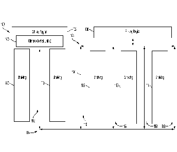
To illustrate the foregoing in greater detail, FIG. 1 illustrates a schematic
diagram of a
storage location 100 according to an example. The storage location 100 may
include any area in
which goods are stored, such as a warehouse, a fulfillment center, a stock
room of a retail
location, a distribution center, and so forth. The storage location 100
includes a chilled region
102, an ambient region 104, and a picking region 106. The chilled region 102
includes one or
more climate-control units 108, shelving 110, an aisle 112 between the
shelving 110, and a point
of ingress and egress 114. The ambient region 104 includes shelving 116 and
aisles 118 between
and around the shelving 116. It is to be appreciated that the particular size
and arrangement of
the regions 102-106 is for purposes of example only, and that alternate sizes,
arrangements, and
proportions of the regions 102-106 are within the scope of the disclosure.
The storage location 100 may be traversable along paths 120 throughout the
storage
location 100. For example, the paths 120 may be traversable by humans, robots,
or a
combination of both (including, for example, humans operating machinery).
Although the paths
120 are designated with double-ended arrows, in some examples, the paths 120
may be divided
into one-way paths. Similarly, although the chilled region 102 is illustrated
with the single point
6
Date Recue/Date Received 2021-07-23
of ingress and egress 114, in some examples, the chilled region 102 may
include a point of
ingress and a separate point of egress.
As indicated above, goods may be stored in containers which are, in turn,
stored on the
shelving 110 or 116. Goods that are intended to be stored in refrigerated
environments may be
stored in containers that are stored on the shelving 110 in the chilled region
102. The one or
more climate-control units 108 may chill the chilled region 102 to a desired
temperature, and/or
may control the humidity in the chilled region 102 to have a desirable
humidity. Conversely,
goods that do not need to be stored in refrigerated environments may be stored
in containers that
are stored on the shelving 116 in the ambient region 104. The ambient region
104 may not have
climate-control units. In other examples, the ambient region 104 may include
climate-control
units configured to maintain an environment in the ambient region 104 to be
comfortable for
human workers and/or to have desirable conditions for robots and/or machinery,
rather than
controlling the environment based on requirements of goods stored therein. In
still other
examples, the ambient region 104 may include climate-control units configured
to maintain an
environment in the ambient region 104 based on requirements of goods stored
therein, but the
goods may have looser requirements than those in the chilled region 102, such
as by not
requiring that the ambient region 104 be below a freezing point.
Goods stored in the storage location 100 may be subsequently retrieved to
fulfill demand
for the goods. For example, an order for goods stored in the storage location
100 may be
received by an owner or bailee of the goods. The goods specified in the order
may be
subsequently retrieved by determining which container(s) the goods are stored
in, retrieving the
container(s), and bringing them to the picking region 106. At the picking
region 106, goods
corresponding to the order may be picked from the containers and prepared for
delivery to a
customer. For example, the goods may be picked and placed in another
container, which may be
delivered to a customer.
The configuration employed by the storage location 100 as discussed in the
foregoing
example may be disadvantageous. For example, providing a chilled region 102
separate from the
ambient region 104 may limit a flexibility of the storage location 100. The
chilled region 102
must be constructed in advance, such as by erecting insulated walls and
installing the climate-
control units 108. The chilled region 102 cannot easily be expanded or
contracted in size, and
space in the chilled region 102 may be wasted or insufficient if the number of
goods that must be
7
Date Recue/Date Received 2021-07-23
stored in the chilled region 102 is not equal to the capacity of the chilled
region 102 to store
goods. This lack of flexibility may be disadvantageous, especially if a demand
for goods having
certain climate conditions¨and, consequently, a need for storage space that
can provide those
climate conditions¨fluctuates over time, leading to under-utilization of the
chilled region 102
when demand drops and an inability to store enough goods if demand increases.
Furthermore, a
power consumption of the climate-control units 108 may be relatively static
regardless of how
many goods are stored in the chilled region 102, which may waste energy.
In addition, condensation may accumulate on containers removed from the
chilled region
102, which may lead to various disadvantages including an inability for
identifiers or information
on the containers from being read or understood by humans and/or machines.
Human operators
entering the chilled region 102 may also experience physical discomfort when
standing in the
chilled region 102, and machinery is often subject to strict design
requirements to withstand the
low temperatures of the chilled region 102. Accordingly, employing the chilled
region 102 may
lead to several disadvantages.
Examples provided herein include climate-controlled containers capable of
storing goods
therein. The climate-controlled containers may be configured to control an
ambient temperature
and/or humidity inside of the container. The temperature and/or humidity may
be variable, and
may support refrigeration above and below a freezing point. Each container may
include one or
more compaiiments, each of which may have a separately controllable climate.
The containers
may include insulated walls, including an insulated lid capable of being
opened and closed
manually, automatically, or a combination of both. The containers may include
energy storage
devices, such as batteries, or may receive power only from external sources.
The containers may
include outlets for receiving power and/or electrically conductive contacts to
be placed in
electrical connection with a power source, which may include power
distribution rails coupled to
a support, such as shelving, on which the containers are stored or placed. The
containers may
include one or more power output connections to provide electrical power from
the power source
to one or more other containers, which may be positioned near the container.
Accordingly,
examples provided herein yield increased flexibility and reduced cost of
storage locations and
storage generally, while increasing worker comfort and relaxing design
requirements for
container-retrieval robots.
8
Date Recue/Date Received 2021-07-23
FIG. 2 illustrates a storage location 200 according to another example. The
storage
location 200 may include any area in which goods are stored, such as a
warehouse, a fulfillment
center, a stock room of a retail location, a distribution center, and so
forth. The storage location
200 includes a storage region 202 and a picking region 204. The storage region
202 includes a
.. first shelving unit 206a, a second shelving unit 206b, a third shelving
unit 206c, a fourth shelving
unit 206d, and a fifth shelving unit 206e (collectively, "shelving units
206"), and a first aisle
208a on a first side of the first shelving unit 206a, a second aisle 208b
between a second side of
the first shelving unit 206a and a first side of the second shelving unit
206b, a third aisle 208c
between a second side of the second shelving unit 206b and a first side of the
third shelving unit
206c, a fourth aisle 208d between a second side of the third shelving unit
206c and a first side of
the fourth shelving unit 206d, a fifth aisle 208e between a second side of the
fourth shelving unit
206d and a first side of the fifth shelving unit 206e, and a sixth aisle 208f
on a second side of the
fifth shelving unit 206e (collectively, "aisles 208").
In some examples, the first shelving unit 206a optionally includes a first
power source
210a, the second shelving unit 206b optionally includes a second power source
210b, the third
shelving unit 206c optionally includes a third power source 210c, the fourth
shelving unit 206d
optionally includes a fourth power source 210d, and/or the fifth shelving unit
206e optionally
includes a fifth power source 210e. The storage location 200 is traversable
(for example, by
human workers, robots, machinery, or any combination thereof) via paths 212,
which may be
unidirectional, bidirectional, or a combination of both.
Each of the shelving units 206 may include one or more shelves to store goods.
In some
examples, the goods may be stored in containers. The containers may be placed
on the shelves
for storage and/or subsequent retrieval. As discussed in greater detail below,
some containers
may be climate controlled. For example, a climate-controlled container may
control a climate
within the container to have an environment desirable for certain goods to be
stored in the
climate-controlled container. Other containers may not be climate controlled,
such as containers
storing goods that may reasonably be stored at typical room temperatures. Non-
climate-
controlled containers may be referred to herein as "ambient containers." In
various examples, the
shelving units 206 are capable of storing any combination of climate-
controlled containers and
ambient containers in any configuration. That is, climate-controlled
containers can be placed in
the storage location 202, even though the storage location 202 itself may not
have an
9
Date Recue/Date Received 2021-07-23
environment meeting the requirements of goods stored in the containers, at
least because the
containers themselves are climate controlled. The storage location 202 is thus
highly flexible at
least because a wide range of goods may be stored in any combination without
limitation by the
goods' climate requirements.
The climate-controlled containers may receive electrical power from the power
sources
210. The power sources 210 may include, for example, a mains utility
connection, a generator,
an uninterruptible power supply, or any other source of electrical power. In
some examples, the
storage location 200 may include a single mains utility input that distributes
power to each of the
shelving units 206, or may include multiple mains utility inputs that each
distribute power to a
subset of the shelving units 206.
Power from the power sources 210 may be distributed to containers stored in a
corresponding one of the shelving units 206. For example, a climate-controlled
container stored
in the first shelving unit 206a may receive power from the first power source
210a. In some
examples, the first power source 210a may provide power to electrified rails
on which containers
are placed in the first shelving unit 206a. The climate-controlled container
may use the power
received via the electrified rails to power a climate-control unit, such as an
air conditioning unit,
to maintain an appropriate temperature and/or humidity inside of the climate-
controlled
container.
FIG. 3 illustrates a process 300 of operation of a storage location according
to an
example. The process 300 may provide an example of activity that may take
place in the storage
location 100, for example, or the storage location 200. The process 300 may be
executed many
times in succession and/or in parallel in some examples.
At act 302, the process 300 begins.
At act 304, an order for goods is received. For example, an order specifying a
list of
desired goods may be received from a customer, the desired goods being stored
in one or more
containers in the storage location 200. The customer may be a shopper in a
retail or grocery
store, for example, and the storage location 200 may be a retail store or
grocery store, or a
warehouse or fulfillment center storing goods to fulfill orders in the retail
store or grocery store.
The order may be prepared and transmitted electronically, and received by a
computing device
in, or communicatively coupled to entities in, the storage location 200. The
desired goods
included in the order may include combinations of goods pertaining to a wide
variety of climate
Date Recue/Date Received 2021-07-23
conditions, including goods that should be stored at a below-freezing level
and goods that may
be stored at a room temperature.
At act 306, a determination is made as to which container or containers
contain the goods
listed in the order received at act 304. For example, a computing device
receiving the order may
maintain or have access to a database indicating a container that one or more
goods are stored in
and a location of the container. The location of the container may be, for
example, a specific
location on a shelf of the shelving units 206. Act 306 may include determining
that multiple
containers must be accessed to obtain the goods at least because no single
container may include
all of the goods in the order.
At act 308, containers determined to contain the ordered goods are retrieved.
For
example, act 308 may include instructing one or more robots to travel to the
location of the
container and retrieve the container via a wired or wireless connection. In
other examples, act
308 may include instructing one or more human workers to retrieve the
container(s) in lieu of, or
in addition to, instructing the robot(s) to retrieve the container(s). In
either example, the robot(s)
and/or human worker(s) may traverse the paths 212, which may be one- or two-
directional,
through the aisles 208 to a location on or in one or more of the shelving
units 206 where the
container(s) are stored. The container(s) may include ambient containers,
climate-controlled
containers, or a combination of both.
At act 310, the retrieved container(s) are brought to the picking region 204.
The picking
region 204 may include one or more human workers and/or robots to prepare
specific customer
orders using goods from the retrieved container(s). The human worker(s) and/or
robot(s) that
retrieved the container(s) may deposit the container(s) at the picking region
204.
At act 312, orders are prepared using goods corresponding to the order
received at act
304. Preparing the orders may include extracting, by the human worker(s)
and/or robot(s) at the
picking region 204, goods corresponding to the received orders from the
retrieved container(s).
The extracted goods may be consolidated together, such as by being placed in a
separate,
customer container based on the goods listed in the order. Once all of the
goods corresponding to
the order have been placed in the customer container, the prepared order may
be provided to a
customer.
At act 314, a prepared order is provided to a customer that provided the order
received at
act 304. For example, act 314 may include delivering a customer container
containing the
11
Date Recue/Date Received 2021-07-23
prepared order directly to the customer by a human worker or robot. In another
example, act 314
may include placing the prepared order on a mobile surface, such as a conveyor
belt, which
conveys the prepared order to an area in which a customer awaits an order. The
customer may
then retrieve the prepared order. In still other examples, act 314 may include
providing a
prepared order to a customer via an intermediary, such as the customer's
agent, a common
carrier, and so forth.
At act 316, the process 300 ends.
As indicated above, orders for a wide variety of combinations of goods may be
fulfilled
in the storage location 200. The shelving units 206 may store any combination
of ambient
containers and climate-controlled containers, which enables the storage
location 200 to flexibly
adapt to changes in a distribution of goods stored in the storage location
200. Accordingly,
examples of climate-controlled containers, described in greater detail below
with respect to
FIGS. 4 and 5A-5D, provide significant advantages to the storage location 200.
FIG. 4 illustrates a block diagram of a climate-controlled container 400
according to an
example. The climate-controlled container 400 (or "container 400") includes
one or more
compatiments 402 (or "compatiments 402"), insulated walls 404, one or more
lids 406 (or "lids
406"), one or more climate-control units 408 (or "climate-control units 408"),
one or more
controllers 410 (or "controllers 410"), one or more sensors 412 (or "sensors
412"), one or more
power interfaces 414 (or "power interfaces 414"), one or more energy-storage
devices 416 (or
"energy-storage devices 416"), and one or more communication interfaces 418
(or
"communication interfaces 418").
The compatiments 402 include one or more compatiments, including a single
compaiiment, in which goods can be placed. Each of the compai intents 402
may have
substantially any shape and size, such as a rectangular prism, which may be
the same as or
different than others of the compaiiments 402. In some examples, the
compatiments 402 may
include multiple compaiiments where a depth of one of the compatiments 402
differs from a
depth of another one of the compai intents 402. In various examples, a
shape and/or size of the
compaiiments 402 may be selected based on a size and shape of goods to be
stored in the
compatiments 402. For example, where the container 400 is intended to store
ice cream cartons,
________________________________ a size and shape of at least one of the
compai intents 402 may be configured to optimize a spatial
efficiency for storing the ice cream cartons.
12
Date Recue/Date Received 2021-07-23
The insulated walls 404 include walls that enclose the compai intents 402.
The insulated
walls 404 include at least the sides of the container 400 and the bottom of
the container 400. In
examples in which the compat __ intents 402 include multiple compaiiments, the
insulated walls
404 may include walls or dividers inside of the container 400 that divide the
compaiiments 402.
The insulated walls 404 may include, or be composed of, one or more thermally
insulative
materials such that an effect of an ambient environment outside of the compai
intents 402 does
not substantially affect a climate inside of the compai intents 402. In
some examples, the
insulated walls 404 may house all other components and aspects of the
container 400. In other
examples, the insulated walls 404 may house only a subset of the components
and aspects of the
container 400, and other components, such as the climate-control units 408,
may be external to
the insulated walls 404 and removably attached to the insulated walls 404.
Certain components
of the container 400 may be inside of at least some of the insulated walls
404. For example,
certain aspects of the climate-control units 408, such as the climate-control
units 408 and the
power interfaces 414, may be inside of, or pass through, the insulated walls
404.
The lids 406 include one or more lids which may seal the compatiments 402 from
an
ambient environment, and which may be removed to access goods stored in the
compaiiments
402. In examples in which the compatiments 402 include multiple compartments,
the lids 406
may include a respective lid for each of the compaiiments 402, or may include
a single lid, or
may include a number of lids between one and the number of compat intents
402. The lids 406
may include, or be composed of, one or more thermally insulative materials
similar or identical
to those of the insulated walls 404. In some examples, the lids 406 may be
opened and/or closed
mechanically or electromechanically. For example, the lids 406 may include a
coupling point to
couple to a device or component configured to open the lids 406. Such a
coupling point may
include a groove configured to be coupled to an automated lid-opening device,
such as a robotic
arm configured to mate with the groove and open the lids 406. In various
examples, the lids 406
may be coupled to the insulated walls 404 via one or more hinges, and/or may
be coupled to the
insulated walls 404 via a friction force.
The climate-control units 408 include one or more components configured to
control a
climate inside of the compatiments 402. For example, the climate-control units
408 may include
one or more components configured to control a temperature and/or humidity
inside of the
compatiments 402, such as one or more air conditioning units, thermal electric
coolers, heat
13
Date Recue/Date Received 2021-07-23
sinks, pumps, fans, plumbing through which coolant travels, and so forth. The
climate-control
units 408 may be adjustable based on control signals received from a
controller, such as the
controllers 410.
The controllers 410 include one or more controllers configured to control
operation of the
container 400. For example, the controllers 410 may control the climate-
control units 408 to
control a climate inside of the compai intents 402. For example, the
controllers 410 may
determine a range of temperature values, which may include a range of values
with fixed upper
and lower temperature values or may include only a minimum or maximum value,
and control
the climate-control units 408 to maintain a temperature within the range of
temperature values.
The controllers 410 may implement hysteresis when controlling the climate-
control units 408.
The controllers 410 may be further configured to send, receive, and/or
exchange information
with one or more external devices. For example, the controllers 410 may
transmit information
indicative of a state of the container 400 (for example, power information,
temperature and/or
humidity logging information, whether the climate-control units 408 are
currently operating and
at what capacity, an indication of the lids 406 being left ajar, an indication
of a temperature or
humidity of the compai __ intents 402 being above or below a target condition,
an indication of a
failure of one or more components, and so forth) and transmit the information
to an external
device, such as a central computing device. Similarly, the controllers 410 may
receive
information from an external device, such as information indicative of a
temperature and/or
_________________________________________________________ humidity set-point
that the container 400 should maintain inside the compat intents 402. In
various examples, the controllers 410 may receive information indicative of
the range of
temperature values within which to maintain a temperature of the compai
________ intents 402 and control
the climate-control units 408 based on the received information. In other
examples, the
controllers 410 may facilitate an exchange of other types of information with
an external device
and/or human operators. For example, the container 400 may include one or more
user or
machine interfaces, which may include a display screen, a buzzer, a speaker, a
light-emitting
component, and so forth, to output information to a user or machine.
The sensors 412 include one or more sensors of the same or a differing type.
For
example, the sensors 412 may include one or more temperature sensors, one or
more humidity
sensors, and/or one or more additional kinds of sensors. The sensors 412 may
be
communicatively coupled to the controllers 410 to provide sensor information
to the controllers
14
Date Recue/Date Received 2021-07-23
410. For example, the controllers 410 may receive sensor information
indicative of a sensed
temperature and/or humidity from the sensors 412, and control operation of the
climate-control
units 408 based on the received sensor information. If a sensed temperature or
humidity is above
a maximum temperature or humidity set point, for example, the controllers 410
may control the
climate-control units 408 to reduce the temperature and/or humidity. The
sensors 412 may also
include additional sensors, such as position-tracking sensors (for example,
accelerometers,
magnetic-field sensors, and so forth), current sensors to determine a current
provided to powered
components of the container 400, voltage sensors to determine a voltage across
powered
components of the container 400, sensors to determine whether the lids 406 are
open or closed
(for example, infrared sensors, acoustic sensors, range sensors, and so
forth), or other types of
sensors, some of which may be included in one or more other components of the
container 400,
such as the climate-control units 408.
The power interfaces 414 include one or more power interfaces to exchange
power
between the container 400 and one or more external devices, components, or
sources. Power
received at the power interfaces 414, which may include alternating-current
and/or direct-current
power, may be distributed to components of the container 400, such as the
climate-control units
408, the controllers 410, the sensors 412, the energy-storage devices 416,
and/or the
communication interfaces 418. For example, the power interfaces 414 may
include an outlet to
receive a corresponding plug, through which power may be provided to the
containers 400 from
a power source, such as the power sources 210. In another example, the power
interfaces 414
may include a wireless power interface to receive power via induction or RF.
In still other
examples, the power interfaces 414 may include one or more electrical contacts
to electrically
couple to corresponding power-delivery components. For example, the power
interfaces 414 may
include at least two electrically conductive contacts, a first one of which
may be coupled to an
electrified rail (for example, an electrified rail of a shelf on which the
container 400 is placed in
the shelving units 206) and a second one of which may be coupled to a grounded
rail (for
example, a ground rail of a shelf on which the container 400 is placed in the
shelving units 206).
In this example, power may be delivered by a power source coupled to the
electrified rail and the
grounded rail, such as the power sources 210. In some examples, the power
interfaces 414 may
provide and/or receive power to and/or from other climate-controlled
containers, which may be
stacked on top of or beneath the container 400.
Date Recue/Date Received 2021-07-23
In some examples, the controllers 410, whether individually or in combination
with the
sensors 412, may sense whether power is available via the power interfaces
414. For example,
the controllers 410 may determine whether a quality of the power is
acceptable, such as by
having a voltage level within an acceptable range of voltage values. If the
controllers 410
determine that acceptable power is available, the controllers 410 may
distribute power from the
power interfaces 414 to other components of the container 400 including, for
example, the
climate-control units 408, the controllers 410, the sensors 412, the energy-
storage devices 416,
and the communication interfaces 418. If the controllers 410 determine that
acceptable power is
not available, then the controllers 410 may control the energy-storage devices
416, if included, to
.. distribute power to components of the container 400 including, for example,
the climate-control
units 408, the controllers 410, the sensors 412, and the communication
interfaces 418. The
controllers 410 may monitor the power interfaces 414 to determine when power
is again
available, if ever, and resume providing power to components of the container
400 from the
power interfaces 414 if power again becomes available.
The energy-storage devices 416 may optionally be included, and may include one
or
more devices or components configured to store electrical energy. For example,
the energy-
storage devices 416 may include one or more batteries, capacitors, flywheels,
and so forth. The
energy-storage devices 416 may be rechargeable and may include one or more
chargers. For
example, the energy-storage devices 416 may be rechargeable using power
received at the power
interfaces 414. In some examples, the energy-storage devices 416 may be
removable or external
to the container 400.
The communication interfaces 418 include one or more interfaces that enable
communicative connection with an external device. For example, the
communication interfaces
418 may include a wired communication interface (for example, a physical
communication port)
and/or a wireless communication interface (for example, an antenna). The
communication
interfaces 418 may enable communication between the controllers 410 and one or
more external
devices, such as a central computing device configured to exchange information
with the
container 400. For example, the controllers 410 may send information
indicative of operation of
the container 400 to an external device via the communication interfaces 418
and/or receive
information indicative of control instructions or information from the
external device via the
communication interfaces 418. Control information may include, for example,
information
16
Date Recue/Date Received 2021-07-23
indicative of a desired temperature set point for the container 400 to
provide. In various
examples, the communication interfaces 418 may include one or more user
interfaces to output
information directly to a user, such as one or more display screens, buzzers,
speakers, light-
emitting components, and so forth, to output information to a user or machine.
An example of the container 400 is provided with respect to FIGS. 5A-5D for
purposes of
example only. The container may be embodied in a different manner than that
shown in FIGS.
5A-5D. Accordingly, it is to be appreciated that the examples provided in
connection with FIGS.
5A-5D are non-limiting with respect to the container 400.
FIG. 5A illustrates a front cross-section view of a climate-controlled
container 500 (or
"container 500") according to an example. FIG. 5B illustrates a side cross-
section view of the
container 500 according to an example. FIG. 5C illustrates a front view of the
container 500
according to an example. FIG. 5D illustrates a back view of the container 500
according to an
example. The container 500 may include an example of the container 400.
The container 500 includes a compai
____________________________________________ intent 502 encapsulated by walls
504 on five sides,
including a bottom side, and a lid 506 on a sixth side. The compatiment 502,
the walls 504, and
the lid 506 may include an example of the compartments 402, the insulated
walls 404, and the
lids 406, respectively. The container 500 further includes a climate-control
unit 508 configured
to provide climate control to the container 500 and, in particular, to goods
stored in the
compatiment 502. The climate-control unit 508 may be removably attached to the
walls 504. In
various examples, the climate-control unit 508 drives coolant through plumbing
510 in the
container 500 (for example, within the walls 504). The container 500 includes
a first fan 512 and
a second fan 514, each of which is configured to drive air flow across
portions of the plumbing
510 into the compatiment 502. The fans 512, 514 may pass through the walls 504
such that air is
drawn from outside of the container 500 and driven across and around the
plumbing 510. The
plumbing 510 may be cooled by coolant flowing therethrough such that air
driven across the
plumbing 510 is cooled. The walls 504 may include a first set of openings 516
located between
the first fan 512 and the compai
_______________________________________________ intent 502, and/or a second
set of openings 518 located between
the second fan 514 and the compai intent 502, such that air (for example,
cooled air) may be
driven into the compatiment 502.
The climate-control unit 508 includes a condenser 520 and a compressor 522.
The
condenser 520 is configured to receive coolant from the compressor 522 via
plumbing 524,
17
Date Recue/Date Received 2021-07-23
condense the coolant, and output the condensed coolant to other components of
the container 500
via the plumbing 510. The compressor 522 is configured to receive coolant from
the plumbing
510 after the coolant has been driven by the condenser 520 through the
plumbing 510, compress
the coolant, and provide the compressed coolant to the condenser 520 via the
plumbing 524. As
the compressed coolant passes through the plumbing 524, a third fan 526 is
configured to drive
air flow across the plumbing 524 through openings 528 in a base of the climate-
control unit 508.
In so doing, a temperature of the plumbing 524, coolant therein, and/or air
surrounding the
plumbing 524 may be lowered.
The climate-control unit 508 further includes an electrical system 530. The
electrical
system 530 may include one or more controllers, power converters, energy-
storage devices,
energy-storage-device chargers, sensors, communication interfaces (including,
for example, user
interfaces and wireless communication interfaces), memory, storage, and so
forth. The electrical
system 530 may be responsible for delivering power to, and controlling
operation of,
components in the container 500. For example, the electrical system 530 may
distribute power
to, and send, receive, or exchange information with, the condenser 520, the
compressor 522, the
fans 512, 514, 526, sensors in the container 500, and/or other components of
the container 500.
Sending, receiving, and/or exchanging information with a component may include
providing
control signals to the component (for example, instructing the component to
turn on, turn off,
change a mode of operation, change a parameter set point, and so forth) and/or
requesting,
polling, or receiving information from the component (for example, requesting,
sensing, or
polling information indicative of a mode of operation, operation parameters,
present and/or past
sensed values, and so forth). The electrical system 530 may include a wired or
wireless
communication interface through which the electrical system 530 sends and/or
receives
information with an external entity, such as a centralized control system. For
example, the
electrical system 530 may receive control information from the centralized
control system
indicative of a temperature set point at which to maintain the container 500,
and/or may send
operational information indicative of operation of, and/or a state of, the
container 500 or
components thereof to the centralized control system.
The electrical system 530 is configured to receive electrical power via
contacts 532, as
illustrated in FIG. 5A, and/or via a power outlet 534, as illustrated in FIGS.
5B and 5D. The
contacts 532 include a first contact 532a and a second contact 532b, each of
which may be
18
Date Recue/Date Received 2021-07-23
coupled to an electrically conductive rail. For example, where the container
500 is placed on
shelving, such as shelving of the shelving units 206, one of the contacts 532
may be placed on an
electrified or powered rail through which current is supplied from a power
source (for example,
one of the power sources 210) to the container 500, and a second one of the
contacts 532 may be
placed on a return or ground rail through which current is returned to the
power source from the
container 500. In another example, such as an example in which the container
500 is configured
to be retrieved by a retrieval robot, the container 500 may receive electrical
power from the robot
via the contacts 532. Power may alternately or additionally be provided from a
power source to
the container 500 via the power outlet 534. For example, a power source may
include a plug
configured to establish an electrical connection with the power outlet 534,
and power may be
provided to the container 500 via the electrical connection. The power source
may include, for
example, the power source 210, or a retrieval robot. In various examples, the
contacts 532 may
be placed on a bottom portion of the container 500, that is, a portion of the
container 500 that
physically contacts a surface on which the container 500 rests, such as a
shelf of the shelving
units 206.
As discussed above, the climate-control unit 508 may be removably attached to
other
components of the container 500, including the walls 504. For example, the
climate-control unit
508 may be removably coupled to other components of the container 500,
including the walls
504, via fasteners 536. The fasteners 536 may establish and/or maintain an
interface between the
climate-control unit 508 and the walls 504 (that is, a point at which or area
across which the
climate-control unit 508 and the walls 504 are in physical proximity or
connection), which may
include one or more connections across which mass and/or energy can be
transferred. For
example, the condenser 520 provides coolant through the plumbing 510 in the
container 500 via
an input coolant connection 538. As the coolant passes through the plumbing
510 back to the
compressor 522, the coolant enters the climate-control unit 508 through an
output coolant
connection 540. The coolant is then received and compressed by the compressor
522 as
discussed above.
As discussed above, the electrical system 530 may be configured to provide
electrical
power to, and send, receive, or exchange information with, components of the
container 500 that
may not be within the climate-control unit 508. For example, the electrical
system 530 may
provide electrical power to the first fan 512, the second fan 514, and/or
other components of the
19
Date Recue/Date Received 2021-07-23
container 500 described in greater detail below, including sensors. Power may
be provided from
the climate-control unit 508 to other components of the container 500, and
information may be
sent, received, or exchanged with other components of the container 500, via a
first electrical
connection 542 and/or a second electrical connection 544. One or more current
signals may be
output by the electrical system 530 via a first of the connections 542, 544
and returned to the
electrical system 530 via a second of the connections 542, 544.
As discussed above, the container 500 may include one or more sensors. As
illustrated in
FIG. 5B, the container 500 may include sensors 546 disposed throughout the
container 500. The
sensors 546 may include one or more types of sensors, such as temperature
sensors, humidity
sensors, light sensors, and so forth. In some examples, the container 500 may
include additional
or fewer sensors than those illustrated in FIG. 5B, and sensors may be
positioned differently than
in the configuration illustrated in FIG. 5B. The sensors 546 may receive power
and/or
information from the electrical system 530, and may send information to the
electrical system
530. For example, the sensors 546 may receive power and a request for sensor
information or
data from the electrical system 530, and the sensors 546 may provide sensor
information or data
to the electrical system 530. Sensor information or data may include
information indicative of
one or more sensed values of an environmental parameter, such as a temperature
measurement, a
humidity measurement, and so forth. As discussed above, the container 500 may
further include
other types of sensors, such as sensors that provide information indicative of
a physical or
geographic location of the container 500, which may be included in the climate-
control unit 508
or other components of the container 500.
The container 500 further includes a user interface 548, as illustrated in
FIGS. 5B and 5C.
The user interface 548 may include one or more user inputs and one or more
user outputs. User
inputs may include buttons, switches, touch-sensitive displays, dials, and so
forth. User outputs
may include light-emitting components, display screens, buzzers, speakers, and
so forth. Users
may interact with the container 500 via the user interface 548. For example,
the user interface
548 may display information indicative of operating conditions of the
container 500 (for
example, a capacity for additional goods, a power consumption, an input power,
current, or
voltage, a temperature, a remaining battery life, a remaining battery runtime,
any error
conditions, a state of the lid 506, such as open or closed, or other operating
conditions) and/or
information indicative of identifying characteristics of the container 500
(for example, where the
Date Recue/Date Received 2021-07-23
container 500 is or should be stored, an indication that the container 500
contains goods
corresponding to an outstanding order, an identification number of the
container 500, what type
of goods the container 500 contains or is intended to contain, and so forth).
The user interface
548 may receive information indicative of desired operating conditions of the
container 500 (for
example, climate set point conditions) and/or information indicative of
identifying characteristics
of the container 500 (for example, where the container 500 is or should be
stored, an
identification number of the container 500, what type of goods the container
500 contains or is
intended to contain, and so forth).
As discussed above, the lid 506 is removably coupled to the walls 504 such
that goods
_______________________________ may be added or removed from the compai
intent 502. The lid 506 includes protrusions 550
towards both sides of the lid 506 configured to mate with openings 552 in both
sides of the walls
504, as illustrated in FIG. 5A. The protrusions 550 mate with the openings 552
to ensure a
suitable coupling between the lid 506 and the walls 504. In some examples, the
container 500
may include one or more sensors configured to detect whether the protrusions
550 are currently
properly mated with the openings 552, such as by the protrusions 550 being
inserted sufficiently
far into the openings 552. The lid 506 further includes a central protrusion
554 along a middle of
the lid 506, as illustrated in FIG. 5A, configured to mate with guides 556 on
a front and back
wall of the walls 504, as illustrated in FIG. 5B, to facilitate opening and/or
closing of the lid 506
without fully removing the lid 506.
The lid 506 includes grooves 558 to facilitate opening, closing, removing,
and/or
inserting the lid 506. The grooves 558 may be angled and/or contoured. A human
user may be
capable of inserting her fingers into the grooves 558 to more easily handle
the lid 506. Similarly,
a robot or machine may be configured to remove the lid 506 from the container
500, and the
grooves 558 may provide a means of mating between a protrusion or other
component of the
robot or machine and the lid 506. A dimensionality and/or material of the lid
506 may be
selected such that, when the lid 506 is coupled with the walls 504, the
compaiiment 502 is sealed
from an ambient environment. The seal may be partial in some examples, at
least because air
flow through the compai __ intent 502 may be desirable to output heat exhaust,
draw air across the
plumbing 510, and so forth. In other examples, the seal created by the lid 506
may render the
compaiiment 502 entirely airtight.
21
Date Recue/Date Received 2021-07-23
In various examples, the container 500 may include additional, fewer, or
different
components. For example, the container 500 may include multiple compaiiments
of the same or
varying dimensions. Each compartment may be separated by one or more walls,
which may be
insulated and removable. The container 500 may further include multiple
climate-control units.
.. For example, the container 500 may include multiple climate-control units,
each of which
controls a climate of a respective one of multiple compai ________ intents.
Each compat .. intent may further
include multiple sensors to provide sensed information to an electrical
system, which may be
shared by components corresponding to each individual compaiiment.
Furthermore, components
of the container 500 may be positioned and/or oriented differently than the
positions and
orientations illustrated in connection with the container 500.
For example, although in some examples the power interfaces 414 may include
electrically conductive contacts and/or a power outlet (for example, similar
to the contacts 532
and the power outlet 534), in some examples, the power interfaces 414 may
alternately or
additionally include wireless power interfaces, such as an induction power
interface, a radio-
frequency power interface, and so forth. For example, in the context of the
container 500, the
electrical system 530 may include, or be coupled to, a wireless power
interface, which may
include an induction power interface and/or a radio-frequency power interface.
As discussed
above, the power interfaces 414 may receive power from a power source such as
the power
sources 210, and may further include a power source provided by a retrieval
robot.
Furthermore, while some examples of the climate-control units 408 may employ
vapor-
compression refrigeration (for example, through implementation of a condenser
and compressor,
such as the condenser 520 and the compressor 522), in some examples the
climate-control units
408 may include one or more thermoelectric coolers in addition to, or in lieu
of, one or more
vapor-compression-refrigeration-based climate-control units. In still other
examples, other
components may be implemented to control a climate of the container 400.
As discussed above, the climate-control unit 508 may be removably coupled to
other
components of the container 500, such as the walls 504, via the fasteners 536.
In some examples,
the fasteners 536 may include screws. In other examples, a climate-control
unit, such as the
climate-control units 408, may be coupled to other components of a container,
such as the
.. container 400, via one or more other types of fasteners in addition to or
in lieu of screws, such as
snaps, clamps, interlocking joints, hook-and-loop, magnets, nails, bolts,
adhesive, and so forth.
22
Date Recue/Date Received 2021-07-23
Although in some examples the lids 406 may be on a top of the container 400,
in other
examples the lids 406 may be coupled to the container 400 at points in
addition to, or in lieu of, a
top of the container 400. For example, one or more of the lids 406 may be
removable from a
front, back, or side of the container 400. The lids 406 may be coupled to the
insulated walls 404
via substantially any removable connection, including via hinges, where the
lids 406 are
rotatable about the hinges and thus remain in physical connection with other
components of the
container 400 but which allow goods to be inserted into or removed from the
compaiiments 402
when rotated into an opened position.
As discussed above, the compaiiments 402 may be chilled to substantially any
desired
temperature range. For example, when storing certain goods, such as ice cream,
the climate-
control units 408 may maintain a temperature of at least one of the
compartments 402 at
approximately -40 F. The climate-control units 408 may maintain a temperature
of another one
of the compai __ intents 402 at another value, such as a temperature above a
freezing point.
Furthermore, at least some of the compaiiments 402 may not be refrigerated and
may instead
__________________________________________________________ remain at an
ambient temperature, regardless of whether or not other compai intents of
the
compatiments 402 are refrigerated.
In some examples, the container 400 may be configured to be stacked with other
containers, which may or may not be climate-controlled containers. The
insulated walls 404
and/or lids 406 may include one or more fasteners configured to facilitate a
physical connection
with other containers. For example, the lids 406 may include one or more
protrusions or
depressions and the insulated walls 404 may include, on a bottom portion of
the container 400,
one or more corresponding depressions or protrusions to mate with those of the
lids 406. In other
examples, other corresponding fasteners may be employed to facilitate a
physical connection
between containers. In still other examples, no fasteners may be employed to
facilitate stacking
.. the container 400 with other containers.
In various examples, the container 400 may be configured to provide power to,
or receive
power from, one or more stacked containers. The power interfaces 414 may
include one or more
input power interfaces to receive power from a stacked container or other
power source, and may
further include one or more output power interfaces to provide power to a
stacked container. For
example, the lids 406 may include one or more power interfaces of the power
interfaces 414 to
provide output power to a container stacked on top of the container 400, and
may include one or
23
Date Recue/Date Received 2021-07-23
more power interfaces of the power interfaces 414 to receive input power from
a container on
which the container 400 is stacked, or another power source, such as a powered
rail, a power
plug coupled to a power outlet of the container 400, and so forth. In this
manner, a bottom-most
container in a stack of containers may receive power from a power source, such
as one of the
power sources 210, and provide a portion of the received power to a second
container stacked on
top of the bottom-most container. The second container may receive the power
and provide a
portion of the power to a third container stacked on top of the second
container, and so forth,
such that an arbitrary number of containers may be stacked on top of one
another and powered
by a power source via each intervening container beneath a stacked container.
In some examples, the power interfaces 414 may include power interfaces to
provide
output power to containers positioned on other sides of the container 400
rather than, or in
addition to, containers stacked on top of the container 400. For example, the
power interfaces
414 may be positioned on the sides, front, and/or back of the container 400,
and the container
400 may provide electrical power derived from a power source to containers
electrically coupled
to the power interfaces 414. In some examples, the container 400 may provide
electrical power
to containers electrically coupled to the power interfaces 414 regardless of
whether or not power
is available to the container from an external power source. For example, the
container 400 may
provide electrical power derived from energy stored in the energy-storage
devices 416.
Although examples are provided in which the container 400 may be implemented
in
connection with storage, for example, storage on shelving units 206, the
containers 400 may be
implemented in additional conditions. For example, the container 400 may be
used in connection
with an order-staging area, such as the picking region 204, such that goods in
a staging, waiting,
or picking area may remain in a climate-controlled environment before being
removed and
placed into, for example, a customer container for delivery to a customer.
Moreover, in examples
in which the container 400 is stackable, stacking containers ensures that
space in these staging,
waiting, or picking areas can be used efficiently. The container 400 may also
be implemented in
areas other than traditional storage locations, such as delivery vehicles or
pickup lockers. In each
of these examples, the container 400 may receive electrical power from a power
source, such as a
power source in an order-staging area (which may, for example, be coupled to a
shelving unit
upon which the container 400 is placed and from which the container 400
receives power), a
power source in a delivery vehicle (which may, for example, be coupled to a
shelving unit in the
24
Date Recue/Date Received 2021-07-23
delivery vehicle upon which the container 400 is placed and from which the
container 400
receives power), or a power source in a pickup locker (which may, for example,
be coupled to a
shelving unit in the pickup locker in which the container 400 is placed and
from which the
container 400 receives power). It is to be appreciated that the container 400
may further be
implemented in other examples, such as in connection with shelving units
disposed in locations
not specifically identified above, and may receive power from power sources
other than those
identified above.
Having thus described several aspects of at least one embodiment, it is to be
appreciated
various alterations, modifications, and improvements will readily occur to
those skilled in the art.
Such alterations, modifications, and improvements are intended to be part of,
and within the
spirit and scope of, this disclosure. Accordingly, the foregoing description
and drawings are by
way of example only.
What is claimed is:
Date Recue/Date Received 2021-07-23