Note: Descriptions are shown in the official language in which they were submitted.
CA 03126282 2021-07-08
WO 2020/263349
PCT/US2020/018214
FLUID PUMP SYSTEM FOR GROUNDWATER WELLS WITH INTELLIGENT CYCLE
COUNT AND AIR SUPPLY VALVE MONITORING
CROSS-REFERENCE TO RELATED APPLICATIONS
[0001] This
application is a PCT International Application and claims priority of
United States Patent Application No. 62/866977, filed on June 26, 2019. The
entire
disclosure of the above application is incorporated herein by reference.
FIELD
[0002] The
present disclosure relates to fluid pumps for use with wells, and more
particularly to electronically controlled pump systems for use in dewatering a
wellbore of
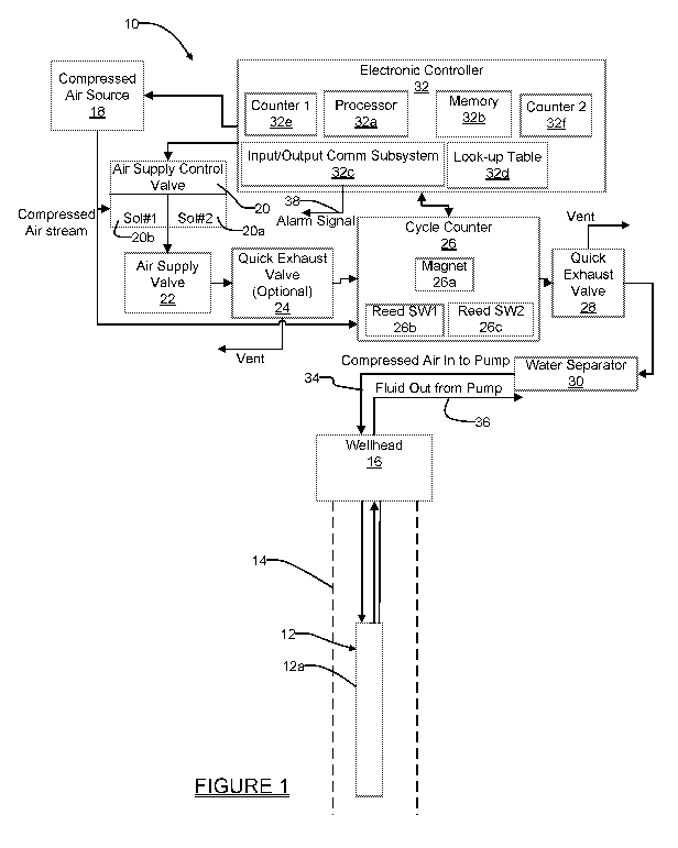
a well or in well gas extraction applications, and enabling control over fluid
discharge and
admission cycles of a pump component while interpreting information from a
well-head
based component to ensure that pump cycling is being carried out in accordance
with
controller generated fluid discharge and fluid admission cycle commands.
BACKGROUND
[0003]
This section provides background information related to the present
disclosure which is not necessarily prior art.
[0004] With
fluid pumps such as groundwater sampling pumps, a cycle counter
has often been included as a subsystem of the pump for counting the number of
cycles
that the pump cycles on and off. Typically these pulse counter subsystems have
involved
the use of a non-mechanical counter, or in some instances the use of a
magnetic sensing
component, such as a Hall effect switch (HES) or a Ratiometric Hall effect
Sensor , which
works together with a linearly movable component, often referred to as a
"shuttle". The
shuttle typically includes a magnet, and the magnet is typically positioned in
a center of
the shuttle. The shuttle typically uses a spring which applies a spring force
to the shuttle
which biases the shuttle towards a home location. The shuttle includes an air
passage
that is able to receive an air flow signal, and when the air flow signal is
acting on the
shuttle, an air pressure differential is created. The air flow differential
creates pressure
that pushes the shuttle to an equilibrium position. The reed switch (e.g.,
HES) generates
a first signal when the shuttle is in its home position, and a different
second signal when
the shuttle has been moved out of the home position in response to a
pressurized airflow
signal.
1
CA 03126282 2021-07-08
WO 2020/263349
PCT/US2020/018214
[0005]
One drawback is that once a controller initiates a fluid discharge cycle by
commanding an air supply solenoid valve to open and admit compressed air into
the
pump, there is no way for the controller to determine if an error condition
has arisen,
where the error condition is preventing termination of the fluid discharge
cycle. For
example, if the air supply solenoid valve becomes stuck in the open position,
compressed
air will be supplied continuously through the air supply solenoid valve into
the interior of
the pump, even though the controller may have removed the "open" signal being
applied
to the air supply solenoid valve. Since the controller will typically allow
the compressed
air to be applied to the pump for a predetermined time to carry out a fluid
discharge cycle
(e.g., five seconds), once the signal from the controller is removed from the
air supply
solenoid valve, the controller would not be apprised that compressed air is
still being
injected into the pump. Put differently, the controller will "assume" that the
air supply
solenoid valve has closed, and that the next fill cycle is commencing. This
condition of
the air solenoid valve being stuck in the "open" position, admitting
pressurized air into the
pump interior, will delay the next "fill" cycle for the pump, which in turn
may allow the fluid
level in the wellbore to rise to an unacceptably high level before it is
recognized that a
problem exits with the air supply solenoid valve.
[0006]
Another error mode which can arise is when the pump controller sends a
signal to open the air valve to start a pumping (i.e., fluid discharge) cycle.
If the air valve
fails to open, the fluid ejection which is supposed to occur during the
pumping cycle will
not happen.
[0007]
Still another error mode which can arise is when the pump controller sends
a signal to open the air valve to start a pumping (fluid discharge) cycle. The
air valve
opens but the air water separator or air supply line to the pump is plugged or
blocked; in
this instance the fluid ejection that is supposed to occur during the pumping
cycle will not
happen.
[0008]
Still another error mode which can arise is when the pump controller sends
a signal to open the air valve to start a pumping cycle. The air valve opens
but the fluid
discharge line is blocked; so the fluid ejection that is supposed to occur
during the
pumping cycle will not happen.
[0009]
Still another error mode which can arise is when the pump controller sends
a signal to open the air valve to start a pumping cycle. The air valve opens,
but Force
Main is blocked; in this instance the fluid ejection which is supposed to
occur during the
pumping cycle will not happen. The Force Main plugging is a common occurrence
which
2
CA 03126282 2021-07-08
WO 2020/263349
PCT/US2020/018214
can be seasonally created when leachate in a wellbore freezes in the force
main, and
particles obstruct the line. In any of these later conditions, the cycle
counter will not be
able to index to keep an accurate cycle count.
SUMMARY
[0010]
This section provides a general summary of the disclosure, and is not a
comprehensive disclosure of its full scope or all of its features.
[0011]
In one aspect the present disclosure relates to a pump system for use in a
well bore of a well. The system comprises a pneumatically actuated fluid pump,
an
electronic controller for controlling operation of the fluid pump; an air
supply control valve;
and a sensing component. The air supply control valve is responsive to
commands from
the electronic controller and in communication with the fluid pump for
admitting a
pressurized airflow from a compressed air source into the fluid pump in
response to a
first command received from the electronic controller, and interrupting the
pressurized
airflow to the fluid pump when a second command is received from the
electronic
controller. The sensing component is in communication with the air supply
control valve
for counting a number of fluid discharge cycles carried out by the fluid pump.
The sensing
component generates a first signal when the movable element is in a first
position,
indicating the pressurized airflow is not flowing through the sensing
component to the
fluid pump; and a second signal when the movable element is in a second
position
indicative of a condition where the pressurized airflow is flowing through the
sensing
component to the fluid pump. The electronic controller may be configured to
use the first
and second signals to detect when the air supply control valve has become
stuck in the
open state after being commanded by the electronic controller to assume a
closed state.
[0012] In
another aspect the present disclosure relates to a pump system for use
in a well bore of a well. The system may comprise a pneumatically actuated
fluid pump;
an electronic controller for controlling operation of the fluid pump; an air
supply control
valve responsive to commands from the electronic controller; and a cycle
counter. The
cycle counter may be in communication with the air supply control valve and
the fluid
pump for receiving the pressurized airflow prior to the pressurized airflow
reaching the
fluid pump, and assisting the electronic controller in counting a number of
fluid discharge
cycles carried out by the fluid pump. The cycle counter may include an axially
movable
magnet and a reed switch component for sensing movement of the magnet in
response
to the presence of the pressurized airflow being supplied through the cycle
counter to the
3
CA 03126282 2021-07-08
WO 2020/263349
PCT/US2020/018214
fluid pump. The cycle counter generates a first signal when the magnet is in a
first
position, indicating the pressurized airflow is not flowing through the cycle
counter to the
fluid pump; and a second signal when the magnet is in a second position
indicative of a
condition where the pressurized airflow is flowing through the cycle counter
to the fluid
pump. The electronic controller may be configured to use the first and second
signals to
detect when the air supply control valve has become stuck in the open state
after a fluid
discharge cycle has completed.
[0013]
In another aspect the present disclosure relates to a method for forming a
pumping system for use in a well bore of a well. The method may comprise
providing a
pneumatically actuated fluid pump disposed in the well bore, using an
electronic
controller to control operation of the fluid pump; using an air supply control
valve for
admitting a pressurized airflow from a compressed air source into the fluid
pump in
response to a first command received from the electronic controller, and
interrupting the
flow of the pressurized airflow to the fluid pump when a second command is
received
from the electronic controller. The method may further include using a sensing
component in communication with the air supply control valve for counting a
number of
fluid discharge cycles carried out by the fluid pump. The cycle counter may
include a
movable element and a sensing element for sensing movement of the movable
element
in response to the presence of the pressurized airflow being supplied to the
fluid pump.
The sensing component may be used to generate a first signal when the movable
element is in a first position, indicating the pressurized airflow is not
flowing through the
sensing component to the fluid pump; and further used to generate a second
signal
indicative of the movable element being in a second position when the
pressurized airflow
is flowing through the sensing component to the fluid pump. The method may
further
comprise using the electronic controller to monitor the first and second
signals to detect
when the air supply control valve has become stuck in the open state after
being
commanded by the electronic controller to assume a closed state.
[0014]
Further areas of applicability will become apparent from the description
provided herein. The description and specific examples in this summary are
intended for
purposes of illustration only and are not intended to limit the scope of the
present
disclosure.
4
CA 03126282 2021-07-08
WO 2020/263349
PCT/US2020/018214
DRAWINGS
[0015]
The drawings described herein are for illustrative purposes only of
selected
embodiments and not all possible implementations, and are not intended to
limit the
scope of the present disclosure.
[0016] Corresponding reference numerals indicate corresponding parts
throughout the several views of the drawings.
[0017]
Figure 1 is a high level illustration illustrating an intelligent pump
system
which is able to detect when an air supply solenoid valve has become stuck in
the open
position;
[0018] Figure
2 is one example of a look-up table which may be used by the
electronic controller of the pumping system of Figure 1 to help determine when
an error
condition involving the solenoid valve exists, based on information supplied
by the cycle
counter shown in Figure 1; and
[0019]
Figure 3 is a high level flowchart illustrating operations in accordance
with
one example of a method carried out by the electronic controller of Figure 1
to detect
when an error condition has arisen with operation of the air supply solenoid
valve.
DETAILED DESCRIPTION
[0020]
Example embodiments will now be described more fully with reference to
the accompanying drawings.
[0021]
The foregoing description of the embodiments has been provided for
purposes of illustration and description. It is not intended to be exhaustive
or to limit the
disclosure. Individual elements or features of a particular embodiment are
generally not
limited to that particular embodiment, but, where applicable, are
interchangeable and can
be used in a selected embodiment, even if not specifically shown or described.
The same
may also be varied in many ways. Such variations are not to be regarded as a
departure
from the disclosure, and all such modifications are intended to be included
within the
scope of the disclosure.
[0022]
Referring to Figure 1 there is shown a pump system 10 in accordance with
one embodiment of the present disclosure. The pump system 10 in this example
may
include a pump 12 disposed in a well bore 14 for pumping fluids collecting
within the well
bore 14. The pump 12 is in communication with a wellhead 16.
[0023]
The system 10 also includes a compressed air source 18, an air supply
solenoid control valve 20 (hereinafter simply "air supply control valve 20")
having a
5
CA 03126282 2021-07-08
WO 2020/263349
PCT/US2020/018214
primary valve 20a and a redundant valve 20b, an air valve 22, an optional
quick exhaust
valve 24, a cycle counter subsystem 26, a quick exhaust valve 28, and a water
separator
30. An electronic controller 32 is included which may include a processor 32a,
a non-
volatile memory 32b (RAM, ROM, etc.), an input/output communication system
32c, a
look-up table 32d, a first counter 32e and a second ("overdrive") counter 32f.
The
input/output subsystem may include one or more of a BLUETOOTH protocol radio,
a
LORA radio, a plug-in controller component, or any other form of wired or
wireless
communication subsystem/circuit/device, etc., which enables either one-
directional or bi-
bi-directional communications with the electronic controller.
[0024] The
electronic controller 32 may generate a signal to turn on the
compressed air source to begin a fluid discharge cycle for the pump 12, and to
cause the
compressed air source to be turned off as well by removing the turn-on signal.
The
electronic controller 32 also communicates with the air supply control valve
20 and
applies commands to open and close the air supply control valve 20, in this
example,
specifically, the primary air supply control valve 20a. It is an important
feature of the
pump system 10 that the electronic controller 32 also receives signals from
the cycle
counter 26, from which it uses the received signals to monitor for and detect
an error
condition arising with the air supply control valve 20, that being that the
primary air supply
control valve 20a does not close, in which case the electronic controller 32
can command
the secondary air supply control valve 20b to close to block the flow of
pressurized air to
the pump 12.
[0025]
This important feature will be discussed in greater detail in the following
paragraphs. The cycle counter 26 is a standard cycle counter for counting pump
cycles
which employs a magnet 26a and at least one reed switch, for example a well-
known
HES, a well-known Ratiometric sensor, etc., which will be referred to
throughout the
following discussion simply as "reed switch" 26b, and where the magnet is
movable
axially in response to the compressed air flowing through the cycle counter
during a fluid
discharge cycle. Optionally, a second reed switch 26c may be used, although
the pump
system 10 may operate with just one reed switch in the cycle counter 26.
[0026] The
reed switch 26b senses a position of the magnet 26a and generates
signals in accordance therewith. The magnet 26a moves from a first or "home"
position,
when no compressed air is flowing through the cycle counter 26, to a second or
"End of
Travel" ("EOT") position when compressed air is flowing through the cycle
counter. The
reed switch 26b senses this movement of the magnet 26a and generates
electrical
6
CA 03126282 2021-07-08
WO 2020/263349
PCT/US2020/018214
signals in accordance with the sensed position of the magnet. If the second
reed switch
26c is used, then the electronic controller 32 will receive signals from both
reed switches
26b and 26c indicating the position of the magnet (e.g., one by reed switch
26b outputting
a "0" signal, indicating the magnet is not present at a first location, while
the second reed
switch 26c outputs a "1" signal, indicating that the magnet is present at the
second
location, and vice versa). These electrical signals are transmitted to the
electronic
controller 32. The magnet/reed switch based cycle counter 26 is well known in
the
industry, and as such further details will not be provided. The precise
location of the
cycle counter 26 may vary from that shown in Figure 1, but in any event it
needs to be
located at some point between the air supply control valve 20 and the pump 12,
in other
words in the path of the pressurized air flowing between air supply control
valve 20 and
the pump 12.
[0027]
The quick exhaust valves 24 and 28 enhance operation of the system 10
but are not absolutely required for satisfactory operation of the system. The
quick
exhaust valve 28 operates automatically to vent either to atmosphere or to a
vacuum line
connected to its "Vent" port, when a predetermined lower limit of air pressure
is reached
within the quick exhaust valve 28. Optional quick exhaust valve 24 operates in
the same
manner, and collectively, the two quick exhaust valves 24 and 28 enable rapid
venting of
the interior of the pump 12 after a fluid discharge cycle is completed, which
helps to
facilitate the immediate start of another fill cycle. Similarly, the water
separator 30 is not
essential for operation of the system 10, but nevertheless is desirable for
removing water
and moisture from the compressed air stream injected into the pump 12, and
thus helping
to prolong the life of valving components exposed to the compressed air
stream.
[0028]
A significant problem that can arise is if the primary valve 20a of the air
supply control valve 20 becomes stuck in the open position after a fluid
discharge cycle
is initiated by the electronic controller 32. In that instance, compressed air
will flow
through the air supply control valve 20, to open and allow the air supply
valve 22 to
communicate air from the cycle counter 26, thru the air valve, through the
quick exhaust
valve 28, and through the water separator 30 before entering an airflow line
34 which
leads into a pump casing 12a of the pump 12. The compressed air stream is used
to
eject fluid which has collected within the pump casing 12a out through a fluid
discharge
line 36. While flowing through the cycle counter 26, the magnet 26a will be
held in its
"EOT" position, and this position will be detected by the reed switch 26b.
After a
predetermined fluid eject cycle time (e.g., 3-10 seconds), the electronic
controller 32 will
7
CA 03126282 2021-07-08
WO 2020/263349
PCT/US2020/018214
remove the signal to the air supply control valve 20, but because the primary
valve 20a
of the air supply control valve 20 will have become stuck in the "open"
condition,
compressed air will continue to be admitted to the interior of the pump casing
12a, and
the electronic controller 32 would ordinarily have no way of knowing that this
condition
has arisen.
[0029]
The pump system 10 addresses the above condition where the primary
valve 20a of the air supply control valve 20 has become stuck in the "open"
position by
monitoring the signals received from the cycle counter 26. Ordinarily, these
signals would
just be used by the electronic controller 32 to maintain an on-going count of
pump cycles,
and possibly to save the count in the memory 32b for use in a future
evaluation of pump
performance and/or to determine when periodic pump maintenance is needed, or
for
other diagnostic or maintenance purposes. However, the pump system 10 also
uses the
electronic controller 32 to analyze the cycle counter 26 signals in relation
to when
expected transitions of the magnet 26a position within the cycle counter 26
should be
occurring.
[0030]
In one aspect the electronic controller 32 intelligently determines that at
the
end of a fluid discharge cycle, which for example may last for a predetermined
time
period, a change in position of the magnet 26a should trigger a corresponding
signal from
the reed switch 26b of the cycle counter 26. In other words, the reed switch
26b should
be generating an electrical signal in accordance with the "home" position of
the magnet
26a, in this example a Level "1" signal. If the "home" signal from the reed
switch 26b is
not detected, that is, if the signal being received is still a Level "0"
signal, then the
electronic controller 32 knows that compressed air is still flowing through
the cycle
counter 26 and into the pump 12.
In this event, the electronic controller 32 may then
use its input/output communications subsystem 32c to generate an alarm signal
38. In
one example, the alarm signal 38 may be a wireless signal which is received by
a
monitoring station in a vicinity of the well bore 14, but it need not
necessarily be in the
vicinity of the well bore 14. For example, the alarm signal 38 could be
transmitted
wirelessly to a cloud-based portal which is in turn in communication with a
remote
monitoring center. Still further, the alarm signal 28 could be transmitted via
a wired
connection to a monitoring center. Still further, the alarm signal may be
provided via a
Bluetoothe protocol radio (not shown) integrated into the pump system 10 to a
user's
laptop, smartphone, etc. Still further, the alarm signal 28 could be used to
set a visual
indicator (i.e., LED(s)) at the well head 16. Still further, the alarm signal
38 could be
8
CA 03126282 2021-07-08
WO 2020/263349
PCT/US2020/018214
supplied to a computer connected to a cellular network to notify a technician
via a text
message on the technician's smartphone, or possibly even by an email message
to the
technician, of the error condition. Accordingly, one or more of WiFi,
Bluetoothe protocol,
and hard wired connections may be used to transmit the alarm signal 38 to an
individual
or entity as needed by a given application.
[0031]
Figure 2 shows one example of the look-up table 32d which may be stored
in a suitable memory of the electronic controller 32, and optionally in the
memory 32b.
This example shows how the two reed switch 26b and 26c components may be used,
but the electronic controller 32 can be used with just a single reed switch as
well. The
use of two reed switches does provide an additional level of "intelligence"
that the
electronic controller 32 can use to further determine/verify the location of
the magnet 26a
at any given time during a pump cycle.
[0032]
From the look-up table 32d, it can be seen that when the reed switch 26b
has not generated a "1" logic level signal after completion of the
predetermined time
internal and the overdrive time interval, the electronic controller 32 knows
that an error
condition has arisen, and can generate the alarm signal 38 (Figure 1). Error
conditions
may include any of those expressly set forth above concerning the main air
supply valve
being stuck open, stuck closed, the discharge line being blocked, and/or the
force main
being blocked. Also, a restricted air supply can cause similar poppet
movements.
[0033]
Referring to Figure 3, a flowchart 100 illustrates operations that may be
performed by the electronic controller 32 during operation of the pump system
10. At
operation 102 the electronic controller is initially monitoring for a signal
indicating that a
fluid discharge cycle is to be initiated (i.e., pump 12 is presumed to be
full). At operation
104 the electronic controller 32 makes a check to determine if a fluid
discharge cycle
signal has been received. If this check produces a "No" answer, then the
monitoring
operation for a fluid discharge cycle to start continues as operation 102 is
repeated. If
the answer at operation 104 is a "Yes" answer, then the electronic controller
32 starts
counter 1 32e to begin the predetermined time interval for the fluid discharge
cycle. At
operation 108 the electronic controller 32 then sends a signal to the primary
valve 20a of
the air supply control valve 20 to begin admitting air into the pump 12 to
begin the fluid
discharge cycle. At operation 110 the electronic controller 32 makes a check
to
determine if the predetermined time interval (Ti) has expired. If this check
produces a
"No" answer, then operations 108 and 110 are repeated. If the check at
operation 110
produces a "Yes" answer, the electronic controller 32 makes a check at
operation 111 to
9
CA 03126282 2021-07-08
WO 2020/263349
PCT/US2020/018214
determine if the primary valve 20a of the air supply control valve 20 actually
remained
open for the Ti time interval. If this check produces a "No" answer, then the
electronic
controller 32 makes a determination at operation 126 that an error has
occurred, for
example, a Level 2 error, indicating that the fluid pump 12 did not actually
pump for the
Ti interval. The electronic controller 32 will then generate an error signal
at operation
128, will reset all the counters at operation 130, and the pumping cycle will
be terminated
at operation 132.
[0034]
If the check at operation 111 indicates that the fluid pump 12 did remain
open for the Ti interval, then this indicates a good or successful pump cycle
occurred.
The electronic controller 32 then sends a signal to the primary valve 20a of
the air supply
control valve 20 to close, as indicated at operation 112, which cuts off the
pressurized air
supply to the pump 12 to end the fluid discharge cycle.
[0035]
At operation 114 the electronic controller 32 then starts the second time
interval counter 2 32f. The second time interval counter 2 32f is an
"overdrive" counter
intended to provide a short time period to allow the magnet 26a to return to
its "home"
position. A failure to return home within the predetermined time period (e.g.,
twice the
pumping time period) indicates that the primary air supply valve 20a is
hanging open. At
operation 116 the electronic controller 32 makes a check to determine if the
overdrive
time interval counter 2 32f has expired. If this produces a "No" answer, then
operations
114 and 116 are repeated. If the check at operation 116 produces a "Yes"
answer,
indicating that the overdrive counter 32f has timed out, then at operation 118
the
electronic controller 32 makes a check to see if a Level "1" level signal is
now being
received from the reed switch 26b (i.e., that the reed switch 26b has returned
to its home
position). If no Level "1" signal is being received, then from using the look-
up table 32d,
this indicates to the electronic controller 32 that pressurized air is still
being received
through the cycle counter 26, which indicates that the primary valve 20a of
the air supply
control valve 20 is stuck in the open position. At operation 120 the
electronic controller
32 generates the error signal 38 indicating this error condition. The
predetermined and
overdrive counters 32e and 32f may then be reset, as indicated at operation
122. At this
point the electronic controller 32 may command the secondary valve 20b of the
air supply
control valve 20 to close, as indicated at operation 124, to interrupt the
pressurized airflow
to the pump 12.
[0036]
If the check at operation 118 indicates that a Level "1" signal is detected
after the additional (i.e., overdrive) time interval has expired, then from
the look-up table
CA 03126282 2021-07-08
WO 2020/263349
PCT/US2020/018214
32d, this enables the electronic controller 32 to verify that the primary
valve 20a of the
air supply control valve 20 has actually closed after the pump discharge cycle
time has
completed, and the next fill cycle is beginning. The overdrive counter 32f may
be then
be reset, as indicated at operation 134, and the method repeats at operation
102.
[0037] The
pump system 10 thus makes use of the cycle counter 26 for the dual
purpose of 1) counting fluid discharge cycles, and 2) intelligently using the
electrical
signals from the cycle counter 26 to determine when the primary valve 20a of
the air
supply control valve 20 is stuck in the open position. The pump system 10
advantageously provides this additional feature of detecting when the air
supply control
valve 26 is stuck in the open position without the need for any other hardware
components to be integrated into the pump system 10, and with virtually no
additional
cost for the pump system 10. Moreover, the normal control sequence for the
pump
system 10 does not need to be modified. The pump system 10 thus provides a
highly
beneficial feature that enables field maintenance personnel to be quickly
apprised if an
air supply control valve associated with a given fluid pump becomes stuck in
the open
position, as well as a secondary airflow valve that is controlled to interrupt
the flow of
pressurized air to the pump under such condition.
[0038]
It will also be appreciated that the pump system 10 can be constructed to
use any type of wireless communication, or even a plug-in hand held
controller, for
example a gas analyzer, to enable making changes in configuration to the pump
system
10, or to make notes about the well site like gas quality, vacuum vale
setting, orifice plate
used, etc. The data can be stored on the non-volatile memory 32b of the
electronic
controller 32 for future use, or even sent via a desired wireless protocol,
(e.g.,
BLUETOOTH protocol radio, to a smartphone which is in communication with the
a
cloud-based subsystem, or by use of a radio communication link like LoRa to
send the
data to a local gateway for storage, or to be sent to the cloud for remote
data collection.
Those skilled in the art will appreciate that virtually any means of
communicating with the
electronic controller 32, either through a wireless link or a wired link, may
be employed
when implementing the pump system.
[0039] The
foregoing description of the embodiments has been provided for
purposes of illustration and description. It is not intended to be exhaustive
or to limit the
disclosure. Individual elements or features of a particular embodiment are
generally not
limited to that particular embodiment, but, where applicable, are
interchangeable and can
be used in a selected embodiment, even if not specifically shown or described.
The same
11
CA 03126282 2021-07-08
WO 2020/263349
PCT/US2020/018214
may also be varied in many ways. Such variations are not to be regarded as a
departure
from the disclosure, and all such modifications are intended to be included
within the
scope of the disclosure.
[0040]
Example embodiments are provided so that this disclosure will be thorough,
and will fully convey the scope to those who are skilled in the art. Numerous
specific
details are set forth such as examples of specific components, devices, and
methods, to
provide a thorough understanding of embodiments of the present disclosure. It
will be
apparent to those skilled in the art that specific details need not be
employed, that
example embodiments may be embodied in many different forms and that neither
should
be construed to limit the scope of the disclosure. In some example
embodiments, well-
known processes, well-known device structures, and well-known technologies are
not
described in detail.
[0041]
The terminology used herein is for the purpose of describing particular
example embodiments only and is not intended to be limiting. As used herein,
the
singular forms "a," "an," and "the" may be intended to include the plural
forms as well,
unless the context clearly indicates otherwise. The terms "comprises,"
"comprising,"
"including," and "having," are inclusive and therefore specify the presence of
stated
features, integers, steps, operations, elements, and/or components, but do not
preclude
the presence or addition of one or more other features, integers, steps,
operations,
elements, components, and/or groups thereof. The method steps, processes, and
operations described herein are not to be construed as necessarily requiring
their
performance in the particular order discussed or illustrated, unless
specifically identified
as an order of performance. It is also to be understood that additional or
alternative steps
may be employed.
[0042] When
an element or layer is referred to as being "on," "engaged to,"
"connected to," or "coupled to" another element or layer, it may be directly
on, engaged,
connected or coupled to the other element or layer, or intervening elements or
layers
may be present. In contrast, when an element is referred to as being "directly
on,"
"directly engaged to," "directly connected to," or "directly coupled to"
another element or
layer, there may be no intervening elements or layers present. Other words
used to
describe the relationship between elements should be interpreted in a like
fashion (e.g.,
"between" versus "directly between," "adjacent" versus "directly adjacent,"
etc.). As used
herein, the term "and/or" includes any and all combinations of one or more of
the
associated listed items.
12
CA 03126282 2021-07-08
WO 2020/263349
PCT/US2020/018214
[0043]
Although the terms first, second, third, etc. may be used herein to
describe
various elements, components, regions, layers and/or sections, these elements,
components, regions, layers and/or sections should not be limited by these
terms. These
terms may be only used to distinguish one element, component, region, layer or
section
from another region, layer or section. Terms such as "first," "second," and
other
numerical terms when used herein do not imply a sequence or order unless
clearly
indicated by the context. Thus, a first element, component, region, layer or
section
discussed below could be termed a second element, component, region, layer or
section
without departing from the teachings of the example embodiments.
[0044]
Spatially relative terms, such as "inner," "outer," "beneath," "below,"
"lower,"
"above," "upper," and the like, may be used herein for ease of description to
describe one
element or feature's relationship to another element(s) or feature(s) as
illustrated in the
figures. Spatially relative terms may be intended to encompass different
orientations of
the device in use or operation in addition to the orientation depicted in the
figures. For
example, if the device in the figures is turned over, elements described as
"below" or
"beneath" other elements or features would then be oriented "above" the other
elements
or features. Thus, the example term "below" can encompass both an orientation
of above
and below. The device may be otherwise oriented (rotated 90 degrees or at
other
orientations) and the spatially relative descriptors used herein interpreted
accordingly.
13