Note: Descriptions are shown in the official language in which they were submitted.
CA 03126895 2021-07-15
WO 2020/152551
PCT/IB2020/050361
MULTI-LAYER, BIODEGRADABLE COMPOSITES FOR AIR FILTRATION
Summary
In recent years, public awareness of the unhealthy air quality in many
countries has increased
significantly, and air quality improvement products represent a growing need.
For instance, indoor air has
two major classes of contaminants: PM2.5, or small particulate matter, and
VOC's, or airborne chemicals.
Filtration media capable of capturing PM2.5 is highly desirable. In the
meantime, shared interest in
protecting the environment has heightened the importance of sustainable
materials. These trends bring
new challenges to air filter design.
First, for many applications such as the residential heating ventilation and
cooling (HVAC)
filtration, low pressure drop is required for the filter, because high
pressure drop can cause airflow
reduction and hinder the heating/cooling performance of the HVAC system.
Secondly, the dust holding
capacity is also a critical perimeter for filters. Higher dust holding
capacity (DHC) allows the filter to be
used for a longer time without change. since sustainable media made from bio-
based materials are usually
more expensive, it is necessary to reduce the material usage in a filter made
of sustainable material.
Thirdly, the web strength is also very critical because insufficient web
strength will require additional
support for the filter media, which means added manufacturing cost.
The present inventors have created a multi-layer composite with excellent dust
holding
performance and low pressure drop. The filter media disclosed here has utility
in both a flat-web structure
and as a three-dimensional (e.g., pleated) structure in a wide variety of air
filtration applications, e.g., air-
conditioner filters, room air purifier filters, and residential HVAC filters.
The composites of the present
disclosure typically include at least two nonwoven web layers, with at least
one layer including
.. multicomponent, aliphatic polyester fibers. The multicomponent fibers can
include polylactic acid (PLA)
and polybutylene succinate (PBS) arranged as a core/sheath bicomponent fiber,
where the sheath layer
can also be a blend of PLA and PBS. The first or top nonwoven web layer has a
relatively high degree of
bundling amongst its fibers, resulting in enhanced DHC for the web. The second
nonwoven web layer can
also include aliphatic polyester fibers (e.g., PLA fibers), which are
typically but not exclusively
monocomponent fibers. The bottom, second nonwoven web layer offers improved
filtration performance
and low pressure drop across the combined media and good web strength. The
multi-layer composite of
the present disclosure also demonstrates sufficient mechanical strength,
allowing it to be used without a
separate support layer, leading to a potential reduction in manufacturing cost
and complexity.
In certain advantageous embodiments, the multilayer articles may be
dimensionally stable and
lack non-biodegradable stabilizers (e.g., polypropylene) and viscosity
modifiers. This is in stark contrast
to typical nonwoven webs and composites made from PLA.
1
CA 03126895 2021-07-15
WO 2020/152551
PCT/IB2020/050361
In one aspect, the present disclosure provides a multi-layered composite
comprising: a first layer
comprising a first nonwoven web, the web including multicomponent fibers; and
a second layer
comprising a second nonwoven web adjacent the first layer, wherein the first
nonwoven layer has a Fiber
Bundling Index of at least 3.
In another aspect, the present disclosure provides a multi-layered composite
comprising: a first
layer comprising a first spunbonded web, the web including bicomponent fibers;
and a second layer
comprising a second spunbonded web affixed to the first layer, wherein the
bicomponent fibers include
one of a sheath comprising PBS and a core comprising PLA, and a sheath
comprising PLA and a core
comprising PBS, and wherein the second spunbonded web includes PLA, and
wherein the composite
lacks at least one of a viscosity modifier and a polypropylene stabilizing
additive.
The multi-layered composites are well suited for use in both flat and pleated
air filters. Such
filters may have a Dust Holding Capacity (DHC) of at least 40 g/m2, and a
pressure drop of no greater
than 0.15 mmH20.
As used herein, the term "m.p." refers to melting point or melting range as
indicated.
As used herein, "Solidity" describes a dimensionless fraction (usually
reported in percent) that
represents the proportion of the total volume of a nonwoven web that is
occupied by the solid (e.g.,
polymeric filament) material. Loft is 100% minus Solidity and represents the
proportion of the total
volume of the web that is unoccupied by solid material.
As used herein, the term "spunbonded" refers to a nonwoven web comprised of
meltspun fibers,
at least some of which fibers exhibit fiber-fiber bonds, e.g., as provided by
autogenous bonding as
described later herein.
As used herein, the term "meltspun" refers to fibers that are formed by
extruding filaments out of
a set of orifices and allowing the filaments to cool and solidify to form
fibers, with the filaments passing
through an air space (which may contain streams of moving air) to assist in
cooling the filaments and
passing through an attenuation (i.e., drawing) unit to at least partially draw
the filaments.
As used herein, the term "Quality Factor" is a figure of merit for the overall
performance of a
filter media in filtering particles from air, and is defined and discussed
later herein.
As used herein, the term "self-supporting" denotes a spunbonded web that
exhibits sufficient
mechanical integrity to be handled and subjected to conventional web handling
processes (e.g., winding,
unwinding, and the like).
As used herein, the term "pleated" refers to a web having at least portions of
which have been
folded to form a configuration comprising rows of generally parallel,
oppositely oriented folds.
As used herein, the term "web" denotes a mass of nonwoven fibers that are
bonded to each other
sufficiently that the mass of fibers has sufficient mechanical integrity to be
handled as a self-supporting
layer; e.g., that can be handled with conventional roll-to-roll web-handling
equipment.
2
CA 03126895 2021-07-15
WO 2020/152551
PCT/IB2020/050361
As used herein, "biodegradable" refers to materials or products that meet the
requirements of
ASTM D6400-12 (2012), which is the standard used to establish whether
materials or products satisfy the
requirements for labeling as "compostable in municipal and industrial
composting facilities."
As used herein, the term "melt-processable", means a polymer available as a
fluid or that can be
pumped or extruded at the temperatures used to process the multi-layer
articles, and do not degrade or gel
at those temperatures to the extent that the physical properties are so poor
as to be unusable for the
intended application
As used herein, "layer" means a single stratum that may be continuous or
discontinuous over a
surface.
The words "preferred" and "preferably" refer to embodiments of the disclosure
that may afford
certain benefits, under certain circumstances. However, other embodiments may
also be preferred, under
the same or other circumstances. Furthermore, the recitation of one or more
preferred embodiments does
not imply that other embodiments are not useful, and is not intended to
exclude other embodiments from
the scope of the disclosure.
As recited herein, all numbers should be considered modified by the term
"about".
As used herein, "a", "an", "the", "at least one", and "one or more" are used
interchangeably.
Thus, for example, a core comprising "a" pattern of recesses can be
interpreted as a core comprising "one
or more" patterns.
As used herein as a modifier to a property or attribute, the term "generally",
unless otherwise
specifically defined, means that the property or attribute would be readily
recognizable by a person of
ordinary skill but without requiring absolute precision or a perfect match
(e.g., within +/- 20 % for
quantifiable properties). The term "substantially", unless otherwise
specifically defined, means to a high
degree of approximation (e.g., within +/- 10% for quantifiable properties) but
again without requiring
absolute precision or a perfect match. Terms such as same, equal, uniform,
constant, strictly, and the like,
are understood to be within the usual tolerances or measuring error applicable
to the particular
circumstance rather than requiring absolute precision or a perfect match.
The above summary of the present disclosure is not intended to describe each
disclosed
embodiment or every implementation of the present invention. The description
that follows more
particularly exemplifies illustrative embodiments. In several places
throughout the application, guidance
.. is provided through lists of examples, which examples can be used in
various combinations. In each
instance, the recited list serves only as a representative group and should
not be interpreted as an
exhaustive list.
3
CA 03126895 2021-07-15
WO 2020/152551 PCT/IB2020/050361
Brief Description of Drawings
The present disclosure will be further described with reference to the
accompanying drawings, in
which:
Fig. 1 is a cross-sectional illustration of a bilayer composite according to
an embodiment of the
present disclosure;
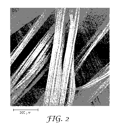
Fig. 2 is a scanning electron micrograph at 340 times magnification in top
view, of a spunbonded
nonwoven web as first layer of a multi-layer composite web;
Fig. 3 is a perspective view of a flat panel filter according to an embodiment
of the present
disclosure;
Fig. 4 is a cross-sectional slice view of a portion of the exemplary framed
air filter of Fig. 3, taken
along line 4-4;
Fig. 5 is a perspective view of an air filter including pleated filter media
according to another
embodiment of the present disclosure; and
Fig. 6 is a schematic diagram of an apparatus which may be used to form a
multi-layered
composite web as disclosed herein;
Layers in certain depicted embodiments are for illustrative purposes only and
are not intended to
absolutely define the thickness, relative or otherwise, or the location of any
component. While the above-
identified figures set forth several embodiments of the disclosure, other
embodiments are also
contemplated, as noted in the discussion. In all cases, this disclosure
presents the disclosure by way of
representation and not limitation. It should be understood that numerous other
modifications and
embodiments can be devised by those skilled in the art, which fall within the
scope and spirit of the
principles of the invention.
Detailed Description
Referring to Fig. 1., exemplary multi-layered composite 10 comprises first
nonwoven web layer
11 having a first and second major surface 12, 13. First nonwoven web layer 11
comprises polymeric
fibers 14. As depicted, the polymeric fibers 14 are bi-component fibers
including a core 15 and sheath
16. The bi-component fibers 14 are arranged in macrobundles 17, in that
several (e.g., four, five, or as
many as eight or more) fibers which are bonded together along a segment of
their length. The multi-
layered composite 10 further comprises second nonwoven layer 20 having first
and second major surface
21, 22. The second nonwoven layer 20 comprises monocomponent fibers 24. In
other embodiments not
depicted, both the first and second nonwoven webs 11, 20 may each include
multi-component fibers, or
both may contain monocomponent fibers. One skilled in the art will immediately
recognize that the fibers
4
CA 03126895 2021-07-15
WO 2020/152551
PCT/IB2020/050361
14, 24 are not drawn to scale and are not arranged in the layers 11, 20 with
any particular purpose other
than for ease of illustration.
The first and second nonwoven layers can be made by techniques known in the
art. Each may be
made using the same or similar technique, or the layers may be created using
disparate techniques and
coupled together in a post-processing step. The nonwoven webs may be made, for
example, by
conventional air laid, carded, stitch bonded, spun bonded, spun-laced, wet
laid, and/or melt blown
procedures. "Meltblowing", as used herein, means a method for forming a
nonwoven fibrous web by
extruding a molten fiber-forming material through a plurality of orifices in a
die to form fibers while
contacting the fibers with air or other attenuating fluid to attenuate the
fibers into fibers, and thereafter
collecting the attenuated fibers. An exemplary meltblowing process is taught
in, for example, U.S. Patent
No. 6,607,624 (Berrigan et al.). "Meltblown fibers" means fibers prepared by a
meltblowing or
meltblown process. "Spun-bonding" and "spun bond process" mean a method for
forming a nonwoven
fibrous web by extruding molten fiber-forming material as continuous or semi-
continuous fibers from a
plurality of fine capillaries of a spinneret, and thereafter collecting the
attenuated fibers. An exemplary
spun-bonding process is disclosed in, for example, U.S. Patent No. 3,802,817
(Matsuki et al.). "Spun
bond fibers" and "spun-bonded fibers" mean fibers made using spun- bonding or
a spun bond process.
Such fibers are generally continuous fibers and are entangled or point bonded
sufficiently to form a
cohesive nonwoven fibrous web such that it is usually not possible to remove
one complete spun bond
fiber from a mass of such fibers. The fibers may also have shapes such as
those described, for example, in
U.S. Patent No. 5,277,976 (Hogle et al.), which describes fibers with
unconventional shapes. Meltspun
fibers can also be distinguished from staple fibers, which are typically cut
to a desired length, in contrast
to meltspun fibers which are typically continuous except for occasional,
statistically-occurring fiber
breaks. Meltspun fibers and spunbonded webs can also be distinguished from,
e.g., carded webs (which
typically exhibit a noticeable fiber alignment imparted by the carding
process, that is not present in
spunbonded webs), and also airlaid webs, wetlaid webs, and so on. "Carding"
and "carding process" mean
a method of forming a nonwoven fibrous web webs by processing staple fibers
through a combing or
carding unit, which separates or breaks apart and aligns the staple fibers in
the machine direction to form
a generally machine direction oriented fibrous nonwoven web. Exemplary carding
processes and carding
machines are taught in, for example, U.S. Patent Nos. 5,114,787 (Chaplin et
al.) and 5,643,397 (Gorman
et al.). "Bonded carded web" refers to nonwoven fibrous web formed by a
carding process wherein at
least a portion of the fibers are bonded together by methods that include for
example, thermal point
bonding, autogenous bonding, hot air bonding, ultrasonic bonding, needle
punching, calendering,
application of a spray adhesive, and the like. Further details regarding the
production and characteristics
of nonwoven webs and laminates including nonwoven webs may be found, for
example, in U.S. Patent
No. 9,469,091 (Henke et al.), which is incorporated by reference in its
entirety herein. "Air-laying" refers
to a process in which bundles of small fibers having typical lengths ranging
from about 3 to about 52
millimeters (mm) are separated and entrained in an air supply and then
deposited onto a forming screen,
5
CA 03126895 2021-07-15
WO 2020/152551
PCT/IB2020/050361
usually with the assistance of a vacuum supply. The randomly oriented fibers
may then be bonded to one
another using, for example, thermal point bonding, autogenous bonding, hot air
bonding, needle
punching, calendering, a spray adhesive, and the like. An exemplary air-laying
process is taught in, for
example, U.S. Patent No. 4,640,810 (Laursen et al.). "Wet-laying" refers to a
is a process in which
bundles of small fibers having typical lengths ranging from about 3 to about
52 millimeters (mm) are
separated and entrained in a liquid supply and then deposited onto a forming
screen, usually with the
assistance of a vacuum supply. Water is typically the preferred liquid. The
randomly deposited fibers
may by further entangled (e.g., hydro-entangled), or may be bonded to one
another using, for example,
thermal point bonding, autogeneous bonding, hot air bonding, ultrasonic
bonding, needle punching,
calendering, application of a spray adhesive, and the like. An exemplary wet-
laying and bonding process
is taught in, for example, U.S. Patent No. 5,167,765 (Nielsen et al).
Exemplary bonding processes are
also disclosed in, for example, U.S. Patent 9,139,940 (Berrigan et al).
In presently preferred implementations, at least the first nonwoven layer
comprises a spunbonded
web. At least some, or all, of the fibers in the first nonwoven layer may be
multicomponent fibers
comprising at least two phases of differing organic polymeric compositions.
Such fibers may have any
suitable configuration, chosen from, e.g., sheath-core, side-by-side, islands-
in-the-sea, and so on. In some
embodiments, such fibers may include at least one organic polymeric phase with
a composition that
promotes or enhances bonding, e.g., melt-bonding, of the fibers to each other.
Multicomponent fibers can
be advantageous in the first layer in that they can provide different
properties to different portions of
individual fibers (e.g., a different melt temperature for the core as compared
to the sheath), and can
contribute to high dust holding through macrobundling, as described in further
detail below.
Multicomponent fibers may suitably include various additives, e.g., one or
more of antioxidants,
plasticizers, processing aids, and so on, may be present for any desired
purpose. In particular
embodiments, the fibers may include a charging additive for the purpose of
allowing a stable electric
charge (an "electret") to be imparted to the fiber. Suitable charging
additives are explored in U.S. Patent
10,273,612 (Song et al.).
In certain embodiments, the first spunbonded web includes a thermoplastic
aliphatic polyester. In
certain exemplary embodiments, the aliphatic polyester is semicrystalline. The
molecular weight of the
thermoplastic polymer(s) is typically chosen so that the polymer is melt-
processable. For polylactide, for
example, the molecular weight may be from about 10,000 to 1,000,000 daltons
and is preferably from
about 30,000 to 300,000 daltons.
In certain embodiments, the thermoplastic aliphatic polyesters of the first
fibrous web are
biodegradable and selected from a group including a poly(lactic acid) (PLA), a
poly(glycolic acid), a
poly(lactic-co-glycolic acid), a polyalkylene succinate such as polybutylene
succinate (PBS), a
polyalkylene adipate, a polyhydroxybutyrate (PHB), a polyhydroxy valerate
(PHV),
polyhydroxyhexanoate (PHEI), polyhydroxybutyrate-hydroxyvalerate copolymers
(PHBV)., and
combinations thereof In further embodiments, the fibers comprise at least one
of naturally occurring
6
CA 03126895 2021-07-15
WO 2020/152551
PCT/IB2020/050361
zein, polycaprolactone, cellulosic ester and combinations thereof In
alternative embodiments that are not
necessarily biodegradable, the fibers may comprise dimer acid polyamide or
polyolefin (e.g.,
polypropylene).
Blends may be made using a variety of other polymers including aromatic
polyesters,
aliphatic/aromatic copolyesters such as those described in U.S. Patent No.
7,241,838, cellulose esters,
cellulose ethers, thermoplastic starches, ethylene vinyl acetate, polyvinyl
alcohol, ethylenevinyl alcohol,
and the like. In blended compositions which include thermoplastic polymers
which are not aliphatic
polyesters, the aliphatic polyester is typically present at a concentration of
greater than 70% by weight of
total thermoplastic polymer, preferably greater than 80% by weight of total
thermoplastic polymer and
most preferably greater than about 90% by weight of thermoplastic polymer.
A PLA polymer or copolymer (e.g., a melt-processable material, in particular a
fiber- forming
resin) contains lactic acid monomer (repeat) units. Such polymers or
copolymers may generally be
derived from monomers chosen from any isomer of lactic acid, such as L-lactic
acid, D-lactic acid, or
mixtures thereof Polylactic acid may also be formed from anhydrides of any
isomer of lactic acid,
including L-lactide, D-lactide, meso-lactide, or mixtures thereof. Cyclic
dimers of such lactic acids and/or
lactides may also be employed. Thus, for example, an L-lactic acid monomer
unit of a polylactic acid will
be understood as being derivable from an L-lactic acid monomer or from any
source that provides an
equivalent monomer unit in the thus-formed polymer. Any known polymerization
method, such as
polycondensation or ring-opening polymerization, may be used to produce such
polymers.
A polylactic acid may be an L-lactic acid or D-lactic acid homopolymer; or, it
may be a
copolymer, such as one that contains L-lactic acid monomer units and D-lactic
acid monomer units. (In
such polymers, a homopolymer or copolymer designation will be a "stereo"
designation based on the
tacticity of the monomer units rather than on the chemical composition.)
Again, such monomer units may
be derived from the incorporation into the copolymer chain of L-lactic acid, D-
lactic acid, L-lactide, D-
lactide, meso-lactide, and so on. In some embodiments, a polylactic acid may
be an L-D copolymer
comprised predominately of L-lactic acid monomer units along with a small
amount of D-lactic acid
monomer units (which may, e.g., improve the melt-processability of the
polymer).
In some embodiments, at least some polylactic acid that is present in the
meltspun fibers may be a
(compositional) copolymer that comprises one or more additional (non-lactic
acid) monomer units. Such
monomer units might include, e.g., glycolic acid, hydroxypropionic acid,
hydroxybutryic acid, and the
like. In various embodiments, lactic acid monomer units (whether L or D, and
being derived from
whatever source) may make up at least about 60, 70, 80, 85, 90, 95, or 99.5
weight % of the meltspun
polylactic acid fibers.
In certain presently preferred implementations, the first nonwoven web layer
includes bi-
component fibers comprising a core material covered with a sheath wherein the
sheath material (with a
lower melting point) melts to bind with other fibers but the core material
(with a higher melting point)
maintains its shape. This combination of component fibers with disparate
melting points may also be
7
CA 03126895 2021-07-15
WO 2020/152551
PCT/IB2020/050361
useful for other multicomponent fiber arrangements, such as side-by-side,
islands-in-the-sea, etc.
Typically, the melting point of the first component polymer of a
multicomponent fiber (e.g.., the core) is
from about 160 C to about 250 C, in some embodiments from about 170 C to
about 240 C, and in
some embodiments, from about 180 C to about 220 C. Typically, the melting
point of the second, low
melting point component can be from about 50 C to about 160 C, in some
embodiments from about
100 C to about 160 C, and in some embodiments, from about 120 C to about
160 C. Moreover, the
melting point of the second component is also typically at least about 20 C,
in some embodiments at
least about 30 C, and in some embodiments, at least about 40 C less than the
melting point of the high
melting point, first component.
Various aliphatic polyesters may be employed as the high melting point
component in the first
nonwoven web of the present disclosure, such as polyesteramides, modified
polyethylene terephthalate,
PLA, polyglycolic acid, polyalkylene carbonates (such as polyethylene
carbonate), PHA, PHB, PHV, and
PHBV. The second component of the multicomponent fiber (e.g., the sheath) may
be formed from one
or more low melting point aliphatic polyesters. Low melting point aliphatic
polyesters are useful in that
they biodegrade at a faster rate than the high melting point polyesters. The
glass transition temperature
("Tg") of the low melting point polyesters may also be less than that of the
high melting point polyesters
to improve flexibility and processability of the polymers. For example, the
low melting point aliphatic
polyesters may have a Tg of about 25 C or less, in some embodiments about 0
C or less, and in some
embodiments, about ¨10 C or less. Such a glass transition temperature may be
at least about 5 C, in
some embodiments at least about 10 C, and in some embodiments, at least about
15 C less than the
glass transition temperature of the high melting point polyesters.
Examples of aliphatic polyesters that may have a suitably low melting point
and glass transition
temperature include aliphatic polyesters with repeating units of at least 5
carbon atoms (e.g.,
polyhydroxyvalerate, polyhydroxybutyrate-hydroxyvalerate copolymer and
polycaprolactone), succinate-
based aliphatic polymers (e.g., PBS). More specific examples may include
polyethylene oxalate,
polyethylene malonate, polyethylene succinate, polypropylene oxalate,
polypropylene malonate,
polypropylene succinate, polybutylene oxalate, polybutylene malonate, PBS, and
blends and copolymers
of these compounds.
The multicomponent fibers of the type described herein may be prepared with or
without
nucleating agents. One type of such a nucleating agent is a multi-carboxylic
acid, such as succinic acid,
glutaric acid, adipic acid, pimelic acid, suberic acid, azelaic acid, sebacic
acid, and mixtures of such acids,
as described in U.S. Patent No. 6,177,193 (Tsai, et al). Preparation of
multicomponent fibers in the
absence of nucleating agents is exemplified in U.S. Patent No. 7,972,692
(Chakravarty et al.). Other
materials that may be used in the preparation of multicomponent fibers include
without limitation,
pigments, antioxidants, wetting agents, stabilizers, surfactants, waxes, flow
promoters, solid solvents,
plasticizers, particulates, and other materials added to enhance the
processability of the thermoplastic
composition. Multicomponent fibers suitable for use in the multi-layered
composites of the present
8
CA 03126895 2021-07-15
WO 2020/152551
PCT/IB2020/050361
invention are exemplified in U.S. Patent Nos. 6,953,622 (Tsai et al.),
7,972,692 (Chakravarty et al.),
7,238,634 (Bansal et al.), 6,953,622 (Tsai et al.), US 8,518,311 (He et al.),
9,487,893 (Moore et al.), and
10,273,612 (Song et al.).
The relative amount of the high melting point and low melting point components
may generally
vary based on the desired properties. For example, the first high melting
point component may constitute
from about 5 wt. % to about 95 wt. %, in some embodiments from about 10 wt. %
to about 90 wt. %, and
in some embodiments, from about 15 wt. % to about 85 wt. % of the total weight
of the multicomponent
fibers. Likewise, the second, low melting point component may constitute from
about 5 wt. % to about 95
wt. %, in some embodiments from about 10 wt. % to about 90 wt. %, and in some
embodiments, from
about 15 wt. % to about 85 wt. % of the total weight of the multicomponent
fibers.
In a presently preferred working example, the first nonwoven web includes a
PLA core and a
PBS/PLA sheath, with the PLA core constituting between about 65 to 95 wt% and
the PBS/PLA sheath
constituting between about 5 to 35 wt.%. A particularly viable spunbonded web
includes bicomponent
fibers having 30 wt.% PBS sheath and 70 wt.% PLA core.
Useful nonwoven webs may have any suitable Effective Fiber Diameter, basis
weight or
thickness that is desired for an application, e.g., air filtration. "Effective
Fiber Diameter" or "EFD" is the
apparent diameter of the fibers in a fiber web based on an air permeation test
in which air at 1 atmosphere
and room temperature is passed through a web sample at a specified thickness
and face velocity (typically
5.3 cm/sec), and the corresponding pressure drop is measured. Based on the
measured pressure drop, the
Effective Fiber Diameter is calculated as set forth in Davies, C. N., The
Separation of Airborne Dust and
Particulates, Institution of Mechanical Engineers, London Proceedings, IB
(1952). The fibers of the first
nonwoven web layer typically have an effective fiber diameter of from at least
20, 25, 30, or 40
micrometers and at most 125, 100, 90, 80, 75, or 50 micrometers. The nonwoven
backing typically has a
basis weight in the range of at least 5, 10, 20, or even 50 g/m2; and at most
800, 600, 400, 200, or even
100 g/m2. Basis weight can be calculated from the weight of a 10 cm x 10 cm
sample and is typically in
the range from about 20 g/m2 to 100 g/m2 for the first nonwoven web layer.
In some embodiments, the first nonwoven web layer may be a high-loft
spunbonded web. As
used herein, this signifies a web that exhibits a Solidity of less than 10.0
%. Solidity is determined by
dividing the measured bulk density of a nonwoven fibrous web by the density of
the materials making up
the solid portion of the web. Bulk density of a web can be determined by first
measuring the weight (e.g.,
of a 10-cm-by-10-cm section) of a web. Dividing the measured weight of the web
by the web area
provides the basis weight of the web, which is reported in g/m2. The thickness
of the web can be
measured by obtaining (e.g., by die cutting) a 135 mm diameter disk of the web
and measuring the web
thickness with a 230 g weight of 100 mm diameter centered atop the web. The
bulk density of the web is
determined by dividing the basis weight of the web by the thickness of the web
and is reported as g/m3.
The Solidity is then determined by dividing the bulk density of the nonwoven
fibrous web by the density
9
CA 03126895 2021-07-15
WO 2020/152551
PCT/IB2020/050361
of the material (e.g., polymer) comprising the solid filaments of the web. The
density of a bulk polymer
can be measured by standard means if the supplier does not specify the
material density.
Loft is usually reported as 100% minus the Solidity (e.g., a Solidity of 7%
equates to a loft of
93%). A higher loft is particularly advantageous in air filtration
applications, as the higher loft can
contribute to enhanced dust holding capabilities, as shown in the Examples
below.
As disclosed herein, webs of Solidity from about 2.0% to less than 12.0%
(i.e., of loft of from
about 98.0% to greater than 88.0%) can be produced. In various embodiments,
webs as disclosed herein
comprise a Solidity of at most about 7.5%, at most about 7.0%, or at most
about 6.5%. In further
embodiments, webs as disclosed herein comprise a Solidity of at least about
5.0%, at least about 5.5%, or
at least about 6.0%.
Without wishing to be bound by theory, the inventors postulate that the
performance advantages
disclosed herein may result at least in part from the use of multicomponent
aliphatic polyesters that bond
together in the spunbonding process. That is, a relatively high number of ropy
aggregated bundles (often
called "macrobundles") comprising several (e.g., four, five, or as many as
eight or more) fibers which are
bonded together along a segment of their length (such fibers are occasionally
called "married" fibers) may
be advantageously formed. While such macrobundles may be present to some
extent in any spunbonded
web, the inventors postulate that an increased amount and size of macrobundles
may be at least partially
responsible for the desirable dust holding properties of the first nonwoven
web layer.
The degree of macrobundling in spunbonded nonwoven webs is characterized as a
Fiber
Bundling Index, defined by comparing the Actual Fiber Diameter (AFD) of the
fibers of the web to the
Effective Fiber Diameter (EFD) exhibited by the web.
Effective Fiber Diamer
Fiber Bundling Index ¨ ______________________________________
Actual Fiber Diameter
Equation 1
As explained in detail in the Examples section, the Actual Fiber Diameter is
obtained by
microscopic observation and represents the (average) actual physical diameter
of the fibers. The inventors
have found that spunbonded webs as disclosed herein unexpectedly exhibit an
Effective Fiber Diameter
which is at least about 100% greater than the Actual Fiber Diameter of the
web, as seen in Table 3 of the
Examples section. For example, Example 1 displays an Effective Fiber Diameter
(52 [im) that is around
350% greater than the Actual Fiber Diameter (15 [im) of the web (that is, the
Fiber Bundling Index is
approximately 3.51). In contrast, the web of Comparative Example 1 displays an
Effective Fiber Diameter
(29.0 [im) that is less than 30% greater than the Actual Fiber Diameter (22.6
[tin) of the web of
Comparative Example 1.
CA 03126895 2021-07-15
WO 2020/152551
PCT/IB2020/050361
Those of ordinary skill in the art will appreciate that the increase in the
Fiber Bundling Index of
Example 1 versus that of the web of Comparative Example 1, occurs despite the
fact that both webs
display quite similar Actual Fiber Diameters (15 [an versus 16 [Lin).
In various embodiments, spunbonded webs useful in the first nonwoven web layer
comprise a
Fiber Bundling Index of at least about 2.0, at least about 2.5, at least about
3.0 or at least about 4Ø
Spunbonded webs useful in the first nonwoven web layer comprise a Fiber
Bundling Index of no greater
than about 10.0, no greater than about 9.5, or no greater than about 8Ø The
degree of bundling is
considerably greater for the first nonwoven layer of the present multi-layered
composites than is typically
advised for spunbonded webs. The macrobundling, and attendant increase in
loft, leads to potentially
exceptional dust holding capacity (DHC) for the mutli-layered composites of
the present disclosure.
As noted above, at least some, or all, of the fibers in the second nonwoven
web can be
monocomponent fibers. The term "monocomponent" refers to the polymeric
material of a fiber and
denotes a fiber in which a continuous phase of uniform polymeric composition
extends across the cross-
section and over the length of the fiber. In some convenient embodiments, a
monocomponent fiber may
be an aliphatic polyester fiber, such as PLA. The term monocomponent does not
necessitate that the
polymeric component material is the only component of the fiber. Rather, in
various embodiments, any
suitable additive, such as those described above, may be present for any
desired purpose.
In other embodiments, the fibers in the second nonwoven web are multicomponent
fibers of the
same or different composition as the fibers in the first nonwoven web layer.
The considerations of
.. multicomponent fibers of the first web above apply equally to the second
nonwoven web. In various
embodiments, nonwoven webs useful in the second nonwoven web layer also
comprise a Fiber Bundling
Index of at least about 2Ø In a presently preferred working example, the
second nonwoven web includes
a PLA core and a PBS/PLA sheath, with the PLA core constituting between about
65 to 95 wt% and the
PBS/PLA sheath constituting between about 5 to 35 wt.%. A particularly viable
spunbonded web
includes bicomponent fibers having 30 wt.% PBS sheath and 70 wt.% PLA core.
The fibers of the second nonwoven web typically have an EFD of from at least
0.1, 1, 2, or even 4
micrometers and at most 125, 75, 50, 35, 25, 20, 15, or 10 micrometers, with
atypical range between 2
and 40 micrometers. The second nonwoven web layer preferably has a basis
weight in the range of at
least 5, 10, 20, or even 50 g/m2; and at most 800, 600, 400, 200, or even 100
g/m2, with a typical range
between 20 and 100 g/m2.
The second nonwoven web may include fibers of the same material type as the
first nonwoven
web, including thermoplastic aliphatic polyesters. The second nonwoven web may
include fibers made
from a blend of thermoplastic materials, including blends made exclusively
from biodegradable materials.
Typically, the fibers of the second nonwoven web in monocomponent embodiments
are comprised
primarily of PLA, that is the PLA constitutes at least about 60 wt.%, in some
embodiments at least about
80 wt.%, and in some embodiments, at least about 90 wt.% of the blend. In a
presently preferred
11
CA 03126895 2021-07-15
WO 2020/152551
PCT/IB2020/050361
example, the second nonwoven web includes blended fibers of 80% by weight PLA
and 20% by weight
PBS, based on the total weight of the composition.
As referenced above, the second nonwoven web layer is presently preferred to
be spunbonded
web, particularly when the first nonwoven web layer is also spunbonded web;
other nonwoven webs (e.g.,
meltblown or airlaid) may be used in other alternative embodiments.
It is believed that web composites made according to the present disclosure
may be dimensionally
stable without the use of polypropylene as a stabilizing agent. Polypropylene,
while leading to improved
stability for certain blown and meltspun webs, is not properly biodegradable
and adds cost to the
manufacturing process. "Dimensionally stable" refers to webs having at least
one dimension which
decreases by no greater than 10% in the plane of the web, when the web is
heated to a temperature above
a glass transition temperature of the fibers. In the plane of the web refers
to the x-y plane of the web,
which may also be referred to as the machine direction and/or cross direction
of the web. Thus, the
multilayered composites described herein can be have at least one dimension in
the plane of the web, e.g.,
the machine or the cross direction, that decreases by no greater than 10%,
when the web is heated to a
temperature above a glass transition temperature of the fibers. In other
circumstances where
biodegradability poses less of a requirement or concern, fibers may be blended
polypropylene in an
amount greater than 0% and no more than 10% by weight of the web, before or
during extrusion, as
described in U.S. Patent No. 9,487,893 (Moore et al.).
Various other optional conventional treatments and additives may be used in
conjunction with the
nonwoven fiber web such as, for example, application of antistatic agents,
lubricants, or corona treatment.
Air Filters
Multi-layer composites of the present disclosure may be formed into, or be
incorporated into, any
desired article, e.g., for purposes of filtration and the like. For such
purposes, the composite 10 may be
conveyed to any desired apparatus such as one or more embossing stations,
laminators, cutters and the
like. If desired, one or more secondary bonding operations (in addition to the
autogenous bonding) may
be performed. Any such operation may be done in-line with the web-producing
operation; or the web may
be wound into a storage roll until such time as it is desired to be further
processed. Additional layers, for
example supporting layers, pre-filter layers, and the like, may be combined
(e.g., by lamination) with the
webs disclosed herein. Thus, in some embodiments the multi-layer articles may
be provided as one or
more of sublayers in a multilayer article. The multi-layer webs of the present
disclosure possess sufficient
strength, however, that support layers are not strictly necessary for use of
the web for air filtration.
In some embodiments, the multi-layer webs as disclosed herein may be used for
filtration, e.g., air
filtration, in flat (unpleated) form. An exemplary flat panel filter is
depicted in Fig. 3 in perspective view
from and shown in Fig. 4 is a cross-sectional slice view of a portion of the
exemplary flat panel filter of
Fig. 3. Filter 100 comprises an upstream side 102 and a downstream side 103
and comprises air filter
media 105 and frame 112 mounted generally on, and surrounding, perimeter 106
of filter media 105
12
CA 03126895 2021-07-15
WO 2020/152551
PCT/IB2020/050361
(here, multi-layer webs of the present disclosure). Flat panel air filter 100
may be rectangular in shape
(which specifically includes square shapes) with corners 144, with filter
media 105 thus having a
generally rectangular perimeter 106. Frame 112 may thus take the form of a
rectangular frame with four
major elongate frame portions that are each mounted on one of the four major
edges of the filter media
and with neighboring frame portions meeting to form corners 111 of frame 112
as shown in Fig. 3.
As shown in Fig. 4, at least one portion of frame 112 comprises a downstream
flange 160 and an
upstream flange 130, which flanges may be generally parallel to each other and
may capture (e.g., pinch)
border portion 107 of filter media 105 therebetween. The frame portion further
comprises outer sidewall
140, which extends outward and downstream from flange 130 and is foldably
connected thereto by fold
line 135; and, inner sidewall 150, which extends outward and downstream from
flange 160 and is
foldably connected thereto by fold line 155, with outer sidewall 140 and inner
sidewall 150 being
foldably connected by fold line 145.
In various embodiments, inner sidewall 150 and outer sidewall 140 may be
positioned at an angle
to each other (when viewed in cross section as shown in Fig. 4, and as
measured from the vertex provided
by fold line 145) of less than about 40, 30, 20, or 10 degrees. In further
embodiments, inner sidewall 150
and outer sidewall 140 may be generally parallel to each other. In specific
embodiments, areas of inner
sidewall 150 and outer sidewall 140 may be bonded, e.g., adhesively bonded, to
each other. Further
considerations and details relating to flat panel filters may be found, for
example, in U.S. Patent No.
8,702,829 (Lise et al.).
In other embodiments, multi-layer articles as disclosed herein may be pleated
to form a pleated
filter. Pleated filters as described herein may be self-supporting, meaning
that they do not collapse or
bow excessively when subjected to the air pressure typically encountered in
forced air ventilation
systems. As noted earlier, in some embodiments a multi-layered composite may
be pleated. Thus as
shown in exemplary embodiment in Fig. 5, a multi-layered composite may
provide, or be a layer of, an air
filter media 200 that is pleated to comprise pleats 201 and pleat tips 202.
The pleating of an air-filtration
media typically serves to increase the total surface area of the media that is
available within a nominal
(plane-projected) area; pleating typically does not significantly change
inherent properties of the media
such as, e.g., loft and Percent Penetration of particles.
The pleat height and pleat spacing of the pleated web may be in any suitable
range. Pleat height
(pleat amplitude) is the distance from upstream tip to downstream tip, along a
direction that is orthogonal
to the overall major plane of the pleated web. Pleat spacing is the distance
between nearest-neighbor
same-side pleat tips, along a direction that is in the major plane of the
filter media. The pleats may have
any desired radius of curvature; for example, they may be relatively
sinusoidal in appearance or they may
be relatively sharp-tipped.
If desired, a pleated air filter media 200 (whether in the form of a multi-
layered composite alone,
or in the form of a multilayer structure of which composite is a filtration
layer), may be stabilized in any
suitable manner. For example, in some embodiments an air filter media may be
equipped with any
13
CA 03126895 2021-07-15
WO 2020/152551
PCT/IB2020/050361
suitable pleat-stabilizing item or items. In general, such items may take the
form of members, strips,
filaments, a collection of filaments, a perforated cardboard sheet, and so on.
Such pleat-stabilizing items
may be in contact with (e.g., bonded to) only the tips of the pleats (as with
exemplary supporting scrim
210 as shown in Fig. 5); or, they may at least partially follow the pleats of
the media and thus may be
bonded to pleat walls and/or valleys as well. Pleat-stabilizing items of the
former type might include, e.g.,
paperboard strips, polymeric strands, and so on. Pleat-stabilizing items of
the latter type might include,
e.g., wire meshes or chicken-wire type metal grids (e.g., that are applied to
the filter media and then
pleated along therewith), beads of drizzle glue that are applied to the
pleated media, filaments that are
extruded onto the surface of the media prior to being pleated, and so on.
In some embodiments, the pleated media may be provided with bridging filaments
that are
bonded to pleat tips of a major side of the pleated media so as to be in
discontinuous or continuous
contact with the media. In some embodiments, the bridging filaments may be of
the general type
described in PCT Patent Application Publication WO 2017/213926 (Gregerson et
al.).
If desired, a perimeter support frame 204 may be mounted on the major edges of
an air filter
.. media 1 (e.g., a pleated air filter media 1) that comprises a multi-layered
composite 10, e.g., as shown in
exemplary manner in Fig. 5. In Fig. 5 a portion of frame 204 has been omitted
in order to show pleats
201; also, it is emphasized that Fig. 5 is an exemplary representation and
that specific features of media
200 (e.g., the shape of pleat tips 202) may vary from that depicted. The
frame, as well as the supporting
elements, may all be made from biodegradable materials.
Multi-layered composites as described herein can exhibit advantageous
filtration properties, for
example high filtration efficiency in combination with low pressure drop and
high dust holding capacity.
Such properties may be characterized by any of the well-known parameters
including percent penetration,
pressure drop, Quality Factor, capture efficiency (e.g., Minimum Composite
Efficiency, Minimum
Efficiency Reporting Value), dust holding capacity (DHC) and the like. In
various embodiments, a multi-
layered composite may exhibit a Dust Holding Capacity of at least 30, 40, 50
or 60 grams per square
meter. In various embodiments, a multi-layered composite may exhibit a
pressure drop of no greater than
0.1, no greater than 0.2, and no greater than 0.3 mm H20.
Methods of Making
Fig. 6 shows an exemplary apparatus which may be used to form a multi-layered
composite
including at least two spunbonded webs. The apparatus includes a first station
500 and a second station
600, with the first station 500 used to create the first nonwoven layer and
the second station 600 used to
create the second nonwoven layer. Each station 500, 600 includes at least an
extrusion head 515, 615, an
attenuator 516, 616, and a quenching stream (not shown), with both stations
500, 600 sharing a collector
surface 519. The first station 500 is positioned upstream from the second
station 600, resulting in
filaments produced at the first station 500 reaching the collector surface 519
first and forming a first mass
14
CA 03126895 2021-07-15
WO 2020/152551
PCT/IB2020/050361
of fibers 520 on the collector surface 519. Filaments from the second station
600 are thus deposited on
the surface of the first fiber mass 520 and form a second mass of fibers 620
thereon.
In an exemplary method of using such an apparatus, polymeric fiber-forming
material is melted
in an extruder and pumped into an extrusion head 510, 610. Extrusion head 510,
610 may be a
conventional spinnerette or spin pack, generally including multiple orifices
arranged in a regular pattern,
e.g., straightline rows. Filaments 511, 611 of fiber- forming liquid are
extruded from the extrusion head
510, 610 and may be conveyed through air-filled space to an attenuator 516,
616. Filaments 511 are
deliberately depicted as bicomponent with a core 512 and a sheath 513, while
filaments 611 are
monocomponent. The distance the extruded filaments 511, 611 travel through air
space before reaching
the attenuator 516, 616 can vary, as can the conditions to which they are
exposed. One or more quenching
streams of air or other gas may be directed toward extruded filaments 511, 611
to reduce the temperature
of, and/or to partially solidify, the extruded filaments 511, 611. Further
details of attenuator 516, 616 and
possible variations thereof are found in U.S. Patent Nos. 6,607,624 (Berrigan
et al.), 6,916,752 (Berrigan
et al.), and 8,240,484 (Fox et al.), and 9,139,940 (Berrigan et al.).
The filaments 511 may pass through the attenuator 516 and then be deposited
onto a generally flat
collector surface 519 where they are collected as a first mass of fibers 520.
The filaments 611 passing
through the attenuator 616 are deposited onto the surface of the first fiber
mass 520 (or a web, if the first
fiber mass is subjected to fiber-fiber bonding upstream of the second
station).
Collector surface 519 may comprise a single, continuous collector surface such
as provided by a
continuous belt or a drum or roll with a radius of at least six inches.
Collector 519 may be generally
porous and gas-withdrawal (vacuum) device can be positioned below the
collector to assist deposition of
fibers onto the collector (porosity, e.g., relatively small-scale porosity, of
the collector does not change
the fact that the collector is generally flat as defined above). The distance
between the attenuator exit and
the collector may be varied to obtain different effects. Also, prior to
collection, extruded filaments may be
subjected to a number of additional processing steps not illustrated in Fig.
1, e.g., further drawing,
spraying, etc.
Any suitable method may be used to couple the individual layers of the multi-
layered composite
together, including, for example, thermal bonding, adhesive bonding, powdered
binder bonding,
hydroentangling, needlepunching, calendering, or a combination thereof Any
such bonding operation
may be done in-line with a web-producing operation; or the first and second
individual webs may be
wound into a storage rolls until such time as it is desired to be further
processed. In some embodiments,
the bonding may involve a thermal treatment (defined broadly herein as meaning
exposure of the mat of
meltspun, collected fibers to a temperature of at least about 80 C), which may
have particular advantages
as discussed herein.
In some embodiments the thermal bonding of the layers may take the form of
autogenous
bonding, defined herein as melt-bonding of fibers to each other at points of
contact therebetween, such
bonding being performed at an elevated temperature without the application of
solid contact pressure onto
CA 03126895 2021-07-15
WO 2020/152551
PCT/IB2020/050361
the mat. In particular embodiments, the autogenous bonding may take the form
of through-air bonding, as
achieved by forcefully passing a stream of heated air through the mats of
collected fibers. Such bonding
may be performed, e.g., by the use of through-air bonder 550 downstream from
the first and second
stations 500, 600. Exemplary through-air bonders are discussed in detail in
U.S. Patent No. 9,139,940
(Berrigan) (which refers to these exemplary through-air bonders as quenched-
flow heaters). Further
guidance on autogenous bonding of fiber mats can be found, for example, in
U.S. Patent Nos. 8,240,484
(Fox et al.) and 10,273,612 (Song et al.).
In order that the disclosure described herein can be more fully understood,
the following
examples are set forth. It should be understood that these examples are for
illustrative purposes only, and
are not to be construed as limiting this disclosure in any manner.
Examples
Table 1: Materials
Material Supplier
BioPBS FZ71 Poly butylene succinate, available from PTT MCC
Biochem Company Limited, Bangkok, Thailand
BioPBS FD92 Poly butylene succinate, available from PTT MCC
Biochem Company Limited, Bangkok, Thailand
Ingeo PLA 6202 Polylactide, available from NatureWorks LLC,
Minnentonka, MN (USA)
Ingeo PLA 6252 NatureWorks LLC, Minnentonka, MN (USA)
TOTAL 3766 PP Polypropylene, available from Total S.A,
Courbevoie, France
Ingeo PLA 6302 Polylactide, available from NatureWorks LLC,
Minnentonka, MN (USA)
Adipic acid Adipic Acid nucleating agent, available from
Sigma-
Aldrich Corporation, St. Louis, MO (USA)
Percent (%) Penetration, Pressure Drop, and Quality Factor
Percent (Particle) Penetration, Pressure Drop and the filtration Quality
Factor (QF) of the nonwoven
fibrous webs can be determined using a challenge aerosol containing DOP
(dioctyl phthalate) liquid
droplets, delivered (unless otherwise indicated) at a flow rate of 85
liters/min to provide a face velocity of
14 cm/s, and evaluated using a TSI (Registered Trademark) Model 8130 high-
speed automated filter
tester (commercially available from TSI Inc., Shoreview, MN). For DOP testing,
the aerosol may contain
particles with a diameter of about 0.185 p.m, and the Automated Filter Tester
may be operated with the
heater off and the particle neutralizer on. Calibrated photometers may be
employed at the filter inlet and
outlet to measure the particle concentration and the % particle penetration
through the filter. An MKS
pressure transducer (commercially available from MKS Instruments, Wilmington,
MA) may be employed
to measure the Pressure Drop (AP, mm H20) through the filter. The equation:
16
CA 03126895 2021-07-15
WO 2020/152551
PCT/IB2020/050361
¨ ln( %Particle Penetration
QF = 100
AP
may be used to calculate QF from the Pressure Drop and Percent (Particle)
Penetration.
Dust Holding Capacity (DHC)
The Dust Holding Capacity (and other filtration properties such as, e.g.,
Capture Efficiency, Arrestance,
and Minimum Efficiency Reporting Value (MERV)) of filters can be measured in
accordance with the
general methods in ASHRAE Standard 52.2 ("Method of Testing General
Ventilation Air-Cleaning
Devices for Removal Efficiency by Particle Size"). The Dust Holding Capacity
test involves configuring
the web as a filter (e.g., a pleated and/or framed filter), installing the
filter into a test duct and subjecting
the filter to incremental dust loading steps, using a synthetic dust as
specified in the ASHRAE 52.2
standard. The Dust Holding Capacity is the total weight of the synthetic dust
captured by the air-filter
sample over all of the incremental dust loading steps. The Dust Holding
Capacity for all samples can be
normalized to the surface area of the air-filter sample and is reported in
grams of dust per square meter.
Fiber Bundling Index
The Effective Fiber Diameter (EFD) of a web is evaluated according to the
method set forth in Davies, C.
N., 'The Separation of Airborne Dust and Particles,' Institution of Mechanical
Engineers, London,
Proceedings TB, 1952. Unless otherwise noted, the test is run at a face
velocity of 14 cm/sec. The Actual
Fiber Diameter (AFD) of fibers in a web is evaluated by imaging the web via a
scanning electron
microscope at 500 times or greater magnification and utilizing an Olympus DP2-
BSW image analysis
program. At least 100 individual diameter measurements are obtained for each
web sample and the mean
of these measurements is reported as the AFD for that web.
Examples 1 - 8
Examples 1-8 were created to examine the Fiber Bundling Index and Pressure
Drop of multilayer
composite webs. Comparative Examples with spunbonded polypropylene fibers,
prepared in the same
general manner as described in US 8,240,484 (Fox et al.), were also examined.
Preparation of the web
The multi-layered composite Examples were prepared as follows, using an
apparatus of the type depicted
in Fig. 6. In Step 1, the PBS/PLA sheath/core filaments are extruded at a
temperature of 200 C to 230 C
(sheath) and 230 C (core), then drawn by quench air at 10 C and the flowrates
of 23 m3/min in Zone 1
and 23 m3/min in Zone 2, to form a PBS/PLA spunbond first composite layer. PLA
monocomponent
filaments are extruded at 230 C, then drawn by a quench air at 15 C and the
flowrate of 12 m3/min, to lay
on the first composite layer to form a dual-layer web. The dual-layer web then
passed through a through-
17
CA 03126895 2021-07-15
WO 2020/152551
PCT/IB2020/050361
air bonding station (i.e., were autogenously bonded), where a hot air of 100 C
¨ 125 C - 130 C was
blown on the dual-layer web to thermally bond the dual-layer web.
Table 2: Spunbonded Web Layer Composition
Example Sheath Composition Core Composition Sheath/Core
Example 1 Sheath: BioPBSFZ71 Ingeo PLA 6202 30 wt.% Sheath
and Ingeo PLA 6202 70 wt.% Core
blend (80 wt.%
PBS/20 wt.% PLA),
and Adipic acid
Example 2 Sheath: BioPBSFD92 Ingeo PLA 6202 8 wt.% Sheath
and Ingeo PLA 6252 92 wt.% Core
blend (80 wt.%
PBS/20 wt.% PLA)
Example 3 Sheath: BioPBSFD92 Ingeo PLA 6202 12 wt.% Sheath
and Ingeo PLA 6252 88 wt.% Core
blend (80 wt.%
PBS/20 wt.% PLA)
Example 4 Sheath: BioPBSFZ71 Ingeo PLA 6202 12 wt.% Sheath
and Ingeo PLA 6202 88 wt.% Core
blend (60 wt.%
PBS/40 wt.% PLA),
and Adipic acid
Example 5 Sheath: BioPBSFZ71 Ingeo PLA 6202 30 wt.% Sheath
and Ingeo PLA 6202 70 wt.% Core
blend (60 wt.%
PBS/40 wt.% PLA),
and Adipic acid
Example 6 Sheath: BioPBSFZ71 Ingeo PLA 6202 12 wt.% Sheath
and Ingeo PLA 6202 88 wt.% Core
blend (80 wt.%
PBS/20 wt.% PLA),
and Adipic acid
Example 7 Sheath: BioPBSFZ71 Ingeo PLA 6202 30 wt.% Sheath
and Ingeo PLA 6202 70 wt.% Core
blend (80 wt.%
PBS/20 wt.% PLA),
and Adipic acid
Example 8 Sheath: BioPBSFZ71 Ingeo PLA 6202 30 wt.% Sheath
and Ingeo PLA 6302 70 wt.% Core
blend (60 wt.%
PBS/40 wt.% PLA),
and Adipic acid
Comparative 1 Not applicable Total 3766 PP 100% Core
Comparative 2 Not applicable Total 3766 PP 100% Core
Comparative 3 Not applicable Total 3766 PP 100% Core
The Pressure Drop and Fiber Bundling Index results, as well as the basis
weight, are provided in Table 3.
18
CA 03126895 2021-07-15
WO 2020/152551
PCT/IB2020/050361
Table 3: Performance for Examples El-E8 and Comparatives 1-3
Example El E2 E3 E4 E5 E6 E7 E8 Comp Comp Comp
1 2 3
Basis 30 30 30 30 30 30 30 30 40 50
55
Weight
(gsm)
EFD 52 62 79 62 48.8 102 57 64.2 29 28
27.5
(microns)
AFD 15 16 17 18 18.8 18 18.7 14.9 22.6
22.5 18.7
(microns)
FBI
3.51 3.78 4.54 3.44 2.60 5.67 3.05 4.31 1.28 1.24 1.47
Pressure
Drop
0.03 0.025 0.015 0.0175 0.0338 0.0075 0.025 0.023 0.2 0.32 0.36
(mm H20
Example 9
Example 9 was created to examine the Fiber Bundling Index and Pressure Drop of
multilayer composite
webs featuring multicomponent fibers in each layer.
Preparation of the web
The multi-layered composite Examples were prepared as follows, using an
apparatus of the type depicted
in Fig. 6. In Step 1, the PBS/PLA sheath/core filaments are extruded at a
temperature of 200 C to 230 C
(sheath) and 230 C (core), then drawn by quench air at 10 C and the flowrates
of 23 m3/min in Zone 1
and 23 m3/min in Zone 2, to form a PBS/PLA spunbond first composite layer. In
Step 2, PBS/PLA
sheath/core filaments are extruded at a temperature of 200 C to 230 C (sheath)
and 230 C (core), then
drawn by quench air at 10 C and the flowrates of 23 m3/min in Zone 1 and 23
m3/min in Zone 2, to form a
PBS/PLA spunbond second composite layer to lay on the first composite layer to
form a dual-layer web.
The dual-layer web then passed through a through-air bonding station (i.e.,
were autogenously bonded),
where a hot air of 100 C ¨ 125 C - 130 C was blown on the dual-layer web to
thermally bond the dual-
layer web.
19
CA 03126895 2021-07-15
WO 2020/152551
PCT/IB2020/050361
Table 4: First Spunbonded Web Layer Composition
Example Sheath Core Composition Sheath/Core
Composition
Example 9 Sheath: Ingeo PLA 6202 30 wt.%
BioPBSFZ71 Sheath
and Ingeo PLA 70 wt.% Core
6202 blend (80
wt.% PBS/20
wt.% PLA),
and Adipic acid
Table 5: Second Spunbonded Web Layer Composition
Example Sheath Core Composition Sheath/Core
Composition
Example 9 Sheath: Ingeo PLA 6202 30 wt.%
BioPBSFZ71 Sheath
and Ingeo PLA 70 wt.% Core
6202 blend (60
wt.% PBS/40
wt.% PLA),
and Adipic acid
Table 6: Performance for Examples E9
Example E9
Basis Weight (gsm) 65
EFD (microns) 36.8
AFD (microns) 15
FBI 2.45
Solidity 5.23%
Pressure Drop (mm
0.15
H20
Dust Holding
38.8 g/m2
Capacity
The recitation of all numerical ranges by endpoint is meant to include all
numbers subsumed within
the range (i.e., the range 1 to 10 includes, for example, 1, 1.5, 3.33, and
10).
CA 03126895 2021-07-15
WO 2020/152551
PCT/IB2020/050361
The patents, patent documents, and patent applications cited herein are
incorporated by reference
in their entirety as if each were individually incorporated by reference. It
will be apparent to those of
ordinary skill in the art that various changes and modifications may be made
without deviating from the
inventing concepts set from above. Thus, the scope of the present disclosure
should not be limited to the
structures described herein. Those having skill in the art will appreciate
that many changes may be made
to the details of the above-described embodiments and implementations without
departing from the
underlying principles thereof. Further, various modifications and alterations
of the present disclosure will
become apparent to those skilled in the art without departing from the spirit
and scope of the invention.
The scope of the present application should, therefore, be determined only by
the following claims and
equivalents thereof.
21