Note: Descriptions are shown in the official language in which they were submitted.
CA 03127035 2021-07-16
WO 2020/159618 PCT/US2019/064397
LOAD BALANCING ARM
FOR MEDICAL DEVICE SUPPORT SYSTEM
Field of Invention
This application relates generally to a load balancing arm for a medical
device
support system or carry system for use in, for example, a hospital examination
room, a clinic, a surgery room or an emergency room, and more particularly to
a
load balancing arm that improves force transmission and reduces spring travel.
lo Background
Medical device support systems, also referred to as suspension systems and
carry systems, are used in health treatment settings such as hospital
examination
rooms, clinics, surgery rooms and emergency rooms. These systems may suspend
or support any variety of medical devices or components including surgical
lights,
-- supply consoles, patient monitors, camera detector heads, medical
instruments,
ventilator systems, suction devices, among others. The support systems
typically
include a central shaft or support column that is suspended from the ceiling
or
mounted to a wall, one or more generally horizontal extension arms mounted for
rotational movement about the shaft, and one or more load balancing arms, also
-- known as counterbalancing arms, that enable positioning of a medical device
to a
proper orientation relative to for example a patient operating table and
healthcare
professionals in the operating room. The extension arms and load balancing
arms
each include a support arm structure or housing, or more generally a support
arm.
For load balancing arms in some medical device support systems or carry
-- systems, there remain various shortcomings, drawbacks, and disadvantages
relative to certain applications. For example, current support systems
typically
utilize load balancing arms having a coil spring with a link running through
the
center. The link, in turn, is attached to a relatively shorter link via a
hinge near a
proximal end of the load balancing arm. The shorter link is then attached to
the
-- proximal hub. Most load balancing arms have a relatively short link that
either
hinges toward the proximal end of the balancing arm structure or attaches to
the
1
CA 03127035 2021-07-16
WO 2020/159618 PCT/US2019/064397
proximal end of the spring. The inventors have found that a short link is not
optimal
for the transmission of the balancing force, which is typically provided by a
counterbalancing spring.
Accordingly, there remains a need for further contributions in this area of
-- technology.
Summary of Invention
The application relates to a load balancing arm for a medical device support
system, in which a link connects at its proximal end to an adjustment bearing
-- element and at its distal end to a distal end of a counterbalancing member
such as
a spring. The inventors have found that the attachment at the distal end of
the
spring allows for a relatively longer link than if connected to the proximal
end of the
spring, and that this longer link allows for a better force transmission and
less spring
travel resulting in a more balanced load balancing arm throughout the
pivotable
-- range of travel of the arm.
According to one aspect of the invention, a load balancing arm for a medical
device support system, includes a proximal hub including a main bearing
element
defining a main pivot axis; an adjustable bearing element defining an
adjustable
pivot axis, wherein the adjustable pivot axis is adjustable relative to the
main pivot
-- axis; a support arm having a proximal end and a distal end, wherein the
distal end is
configured to support a medical device load and the proximal end is pivotably
mounted to the main bearing element for pivotable movement about the main
pivot
axis; a spring extending within a cavity of the support arm and mounted to
exert a
biasing force between the main pivot axis and a distal end of the spring; and,
at
-- least one link having a proximal end pivotably mounted to the adjustable
bearing
element for pivotable movement about the adjustable pivot axis, and a distal
end
pivotably mounted to the distal end of the spring such that the biasing force
exerted
by the spring is transmitted through the link to the adjustable bearing
element
thereby to generate a moment about the main pivot axis of the proximal hub
that
-- counters a moment generated by the medical device load at the distal end of
the
2
CA 03127035 2021-07-16
WO 2020/159618 PCT/US2019/064397
support arm.
Embodiments of the invention may include one or more of the following
additional features separately or in combination.
The distal end of the link may be pivotably mounted to the distal end of the
-- spring via a carriage slide that is slidable relative to the support arm.
The carriage slide may be slidable within at least one groove in the support
arm.
The groove may be oriented along an axis that extends radially from and
perpendicular to the main pivot axis.
lo The spring may be a gas spring having a cylinder and a rod, and the rod
may
be pivotably mounted to the distal end of the at least one link.
The at least one link may include a pair of links that straddle the spring on
laterally opposite sides of the spring.
The support arm may include an intermediate portion between the proximal
-- end and distal end of the support arm, and the intermediate portion may
have a
relatively narrower height span than the proximal end of the support arm, and
the at
least one link may have at least one bend that corresponds to the difference
in
height span between the intermediate portion and the proximal end of the
support
arm.
The load balancing arm may further include a load adjustment screw, and the
adjustable bearing element may include a load adjustment nut that threadably
engages the load adjustment screw to adjust the adjustable pivot axis relative
to the
main pivot axis.
The load adjustment screw may be vertically oriented in the proximal hub
-- and may be rotatably mounted at at least one end for rotation about its own
central
axis, and the load adjustment nut may be configured to move in the vertical
direction as the adjustment screw is rotated, and the vertical movement of the
load
adjustment nut may adjust the adjustable pivot axis relative to the main pivot
axis.
The adjustable bearing element may include a pin that is carried by the load
-- adjustment nut and the proximal end of the link may be pivotably mounted to
the
3
CA 03127035 2021-07-16
WO 2020/159618 PCT/US2019/064397
pin.
The adjustable pivot axis may be adjustable between upper and lower
abutment contacts defined by the proximal hub, and the lower abutment contact
may be above a diameter of the pin.
The at least one link may include a pair of links, and the pair of links may
be
pivotably mounted to the pin.
The main bearing element may include a pair of pins, and the proximal end
of the support arm may include a pair of laterally spaced protrusions that are
pivotably mounted to the respective pins to raise and lower the height of the
medical
device load at the distal end of the support arm.
The proximal end of the at least one link may be pivotably mounted to the
adjustable bearing element.
The adjustable pivot axis may be adjustable relative to the main pivot axis
over a range of adjustment, and the adjustable bearing element and the
proximal
end of the at least one link may be movable between the pair of pins over at
least a
portion of the range of adjustment.
The at least one link may include a pair of links, and the proximal ends of
the
respective pair of links may be pivotably mounted to the adjustable bearing
element.
The adjustable pivot axis may be adjustable relative to the main pivot axis
over a range of adjustment, and the adjustable bearing element and the
proximal
ends of the respective pair of links may be movable between the pair of pins
over at
least a portion of the range of adjustment.
The support arm may have an angle of rotation about the main pivot axis of
about 30 degrees upward from horizontal to about 85 degrees downward from
horizontal.
The adjustable pivot axis may be horizontally offset from the main pivot axis
in a direction toward an axis of rotation of the load balancing arm.
The load balancing arm may further include a parallel link that is pivotably
connected at its proximal end to a pin supported by the proximal hub and at
its
distal end to a pin supported by a distal hub pivotably connected to the
distal end of
4
CA 03127035 2021-07-16
WO 2020/159618 PCT/US2019/064397
the support arm.
The parallel link may include a pair of laterally spaced side walls that
straddle
a vertically lower portion of the spring on laterally opposite sides of the
spring.
The parallel link may include a pair of laterally spaced side walls that
straddle
the at least one link on laterally opposite sides of the at least one link
over at least a
portion of a pivotable range of the load adjustment arm.
According to another aspect of the invention, a medical device support
system comprises a central shaft; an extension arm mounted to the central
shaft for
rotational movement about the shaft; and a load balancing arm including: a
proximal
hub including a main bearing element defining a main pivot axis; a
counterbalancing
bearing element defining a counterbalancing pivot axis; a support arm having a
proximal end and a distal end, wherein the distal end is configured to support
a
medical device load and the proximal end is pivotably mounted to the main
bearing
element for pivotable movement about the main pivot axis; a spring extending
within
a cavity of the support arm and mounted to exert a biasing force between the
main
pivot axis and a distal end of the spring; and at least one link having a
proximal end
pivotably mounted to the counterbalancing bearing element for pivotable
movement
about the counterbalancing pivot axis, and a distal end pivotably mounted to
the
distal end of the spring such that the biasing force exerted by the spring is
transmitted through the link to the counterbalancing bearing element thereby
to
generate a moment about the main pivot axis of the proximal hub that counters
a
moment generated by the medical device load at the distal end of the support
arm.
Embodiments of the invention may include one or more of the following
additional features separately or in combination.
The counterbalancing bearing element may be an adjustable bearing
element, and the counterbalancing pivot axis may be adjustable relative to the
main
pivot axis.
The following description and the annexed drawings set forth certain
illustrative embodiments of the invention. These embodiments are indicative,
however, of but a few of the various ways in which the principles of the
invention
5
CA 03127035 2021-07-16
WO 2020/159618 PCT/US2019/064397
may be employed. Other objects, advantages and novel features according to
aspects of the invention will become apparent from the following detailed
description when considered in conjunction with the drawings.
Brief Description of the Drawings
The annexed drawings, which are not necessarily to scale, show various
aspects of the invention.
Fig. 1 is a perspective view of a medical device support system in
accordance with an embodiment of the invention.
lo Fig. 2 is a side perspective view of a load balancing arm in accordance
with
an embodiment of the invention.
Fig. 3 is a view similar to Fig. 2 with a support arm structure removed to
show internal components of the load balancing arm.
Fig. 4 is a side view of the Fig. 2 load balancing arm.
Fig. 5 is a top view of the Fig. 2 load balancing arm.
Fig. 6 is an end perspective view of the Fig. 2 load balancing arm, showing at
a distal end thereof a connection receptacle for receipt of a medical device.
Fig. 7 is cross section view of the Fig. 2 load balancing arm as viewed from
the plane 7-7 in Fig. 6.
Fig. 8 is a cross section view of the Fig. 2 load balancing arm as viewed from
the plane 8-8 in Fig. 4.
Fig. 9 is a cross section view of the Fig. 2 load balancing arm as viewed from
the plane 9-9 in Fig. 4, without the proximal hub to show internal components
of the
load balancing arm.
Fig. 10 is a cross section view of the Fig. 2 load balancing arm as viewed
from the plane 10-10 in Fig. 4.
Fig. 11 is a cross section view of the Fig. 2 load balancing arm as viewed
from the plane 11-11 in Fig. 4.
Fig. 12 is a perspective view of a proximal end of the load balancing arm,
showing internal components of the load balancing arm.
6
CA 03127035 2021-07-16
WO 2020/159618 PCT/US2019/064397
Fig. 13 is a side perspective view of a load adjustment base of a proximal
hub of the Fig. 2 load balancing arm.
Fig. 14 is a top perspective view of the load adjustment base of the proximal
hub of the Fig. 2 load balancing arm.
Fig. 15 is a side cross section view of the Fig. 2 load balancing arm in a
substantially horizontal position, showing internal components of the load
balancing
arm.
Fig. 16 is a side cross section view of the Fig. 2 load balancing arm in a
position upward from horizontal, showing internal components of the load
balancing
arm.
Fig. 17 is a side cross section view of the Fig. 2 load balancing arm in a
position downward from horizontal, showing internal components of the load
balancing arm.
Fig. 18 is a perspective view of the proximal end of the Fig. 2 load balancing
arm in a substantially horizontal position, with a cover removed to show
internal
components of the load balancing arm.
Fig. 19 is a perspective view of the proximal end of the Fig. 2 load balancing
arm in a position upward from horizontal, with a cover removed to show
internal
components of the load balancing arm.
Fig. 20 is a perspective view of the proximal end of the Fig. 2 load balancing
arm in a position downward from horizontal, with a cover removed to show
internal
components of the load balancing arm.
Fig. 21 is a top perspective view of a load balancing arm in accordance with
another embodiment of the invention, with a support arm structure removed to
show
internal components of the load balancing arm.
Fig. 22 is a partial top perspective view of the Fig. 21 load balancing arm,
shown in partial cross section to show internal components of the load
balancing
arm.
Fig. 23 is a side view of the Fig. 21 load balancing arm, enlarged to show the
proximal and distal ends in more detail.
7
CA 03127035 2021-07-16
WO 2020/159618 PCT/US2019/064397
Fig. 24 is a side cross section view of the Fig. 21 load balancing arm as
viewed from the plane 24-24 in Fig. 25, as though the load balancing arm in
Fig. 25
were whole.
Fig. 25 is a top cross section side view of the Fig. 21 load balancing arm as
.. viewed from the plane 25-25 in Fig. 24, as though the load balancing arm in
Fig. 24
were whole.
Fig. 26 is an end cross section view of the Fig. 21 load balancing arm as
viewed from the plane 26-26 in Fig. 24, as though the load balancing arm in
Fig. 24
were whole.
Fig. 27 is a side cross section view of a proximal end of the Fig. 21 load
balancing arm, showing internal components of the load balancing arm.
Fig. 28 is a side cross section view of a distal end of the Fig. 21 load
balancing arm, showing internal components of the load balancing arm.
Fig. 29 is cross section view of the Fig. 21 load balancing arm as viewed
from the plane 29-29 in Fig. 23.
Fig. 30 is a perspective view of an end portion of a parallel link of the Fig.
21
load balancing arm.
Fig. 31 is a partial cross section perspective view of a proximal end of the
Fig. 21 load balancing arm, showing internal components of the load balancing
arm.
Fig. 32 is a partial cross section perspective view of a proximal end of the
Fig. 21 load balancing arm, showing internal components of the load balancing
arm.
Fig. 33 is a side perspective view of a load adjustment base of a proximal
hub of the Fig. 21 load balancing arm.
Fig. 34 is a side cross section view of the Fig. 21 load balancing arm in a
substantially horizontal position, showing internal components of the load
balancing
arm.
Fig. 35 is a side cross section view of the Fig. 21 load balancing arm in a
position upward from horizontal, showing internal components of the load
balancing
arm.
Fig. 36 is a side cross section view of the Fig. 21 load balancing arm in a
8
CA 03127035 2021-07-16
WO 2020/159618
PCT/US2019/064397
position downward from horizontal, showing internal components of the load
balancing arm.
Fig. 37 is a side cross section view of the distal end of the Fig. 21 load
balancing arm in a position upward from horizontal, showing internal
components of
the load balancing arm.
Fig. 38 is a side cross section view of the distal end of the Fig. 21 load
balancing arm in a position downward from horizontal, showing internal
components
of the load balancing arm.
Fig. 39 is a front perspective view of a load adjustment base and an
adjustable bearing element in accordance with another embodiment of the
invention.
Fig. 40 is a front perspective view of the load adjustment base shown in Fig.
39.
Fig. 41 is a rear perspective view of the adjustable bearing element shown in
Fig. 39.
Fig. 42 is a rear perspective view of the load adjustment base shown in Fig.
39.
Fig. 43 is a front view of the load adjustment base and adjustable bearing
element of Fig. 39.
Fig. 44 is a cross section view of the load adjustment base and adjustable
bearing element of Fig. 39 as viewed from the plane 44-44 in Fig. 43.
Fig. 45 is a rear view of the load adjustment base shown in Fig. 39.
Detailed Description
While the present invention can take many different forms, for the purpose of
promoting an understanding of the principles of the invention, reference will
now be
made to the embodiments illustrated in the drawings and specific language will
be
used to describe the same. It will nevertheless be understood that no
limitation of
the scope of the invention is thereby intended. Any alterations and further
9
CA 03127035 2021-07-16
WO 2020/159618 PCT/US2019/064397
modifications of the described embodiments, and any further applications of
the
principles of the invention as described herein, are contemplated as would
normally
occur to one skilled in the art to which the invention relates.
Fig. 1 shows a medical device support system 10 in accordance with an
embodiment of the invention. The medical device support system 10 includes a
central shaft or support column 14 that is suspended from the ceiling, and
three
generally horizontal extension arms 16 mounted to the shaft 14 for rotational
movement about the shaft 14. The central shaft 14 could be mounted to a wall
or
stand rather than the ceiling. Three load balancing arms 18, which are also
referred
to as counterbalancing arms, are mounted to the respective extension arms 16.
The extension arms 16 and load balancing arms 18 each include a support arm
structure or housing, or more generally a support arm. In the Fig. 1
embodiment, a
proximal hub 22 of the load balancing arm 18 includes a support structure 24,
for
example the illustrative drop tube 24, that is rotatably connectable to a
receptacle at
the distal end 30 of the extension arm 16. The distal end of each load
balancing
arm 18 is configured with a suitable support hub 34 to support a medical
device
load 36. The medical device load 36 may include a surgical light as shown, or
a
supply console, a patient monitor, a camera detector head, a medical
instrument, a
ventilator system, a suction device, among others. A control console, if
provided,
.. may provide controls for navigation of a medical instrument that is either
coupled to
or remote from the load balancing arm 18. The load balancing arm 18 enables
positioning of the medical device 36 to a proper orientation relative to for
example a
patient operating table and healthcare professionals in the operating room.
Turning now to Figs. 2-20, there is shown a load balancing arm 100 of the
medical device support system 10 in accordance with an embodiment of the
invention. The load balancing arm 100 includes a proximal hub 104, an
adjustable
bearing element 108, a support arm 110, a spring 116, and one or more links,
two
such links 124, 126 in the illustrative embodiment, as shown in Fig. 3 and 12.
The
proximal hub 104 may include a support structure 24 such as the drop tube 24
(see
Fig. 1). The proximal hub 104 includes a main bearing element 130 that defines
a
CA 03127035 2021-07-16
WO 2020/159618 PCT/US2019/064397
main pivot axis 132. The adjustable bearing element 108 defines an adjustable
pivot axis 142 that is adjustable relative to the main pivot axis 132. The
support arm
110 has a proximal end 150 and a distal end 152. The distal end 152 is
configured
to support a medical device load 36 (see Fig. 1) and the proximal end 150 is
pivotably mounted to the main bearing element 130 for pivotable movement about
the main pivot axis 132. Pivotable movement about the main pivot axis 132
raises
and lowers the height of the medical device load 36 at the distal end 152.
The spring 116 extends within a cavity 154 of the support arm 110 and is
mounted to exert a biasing force between the main pivot axis 132 and a distal
end
-- 158 of the spring 116. The links 124, 126 each have a proximal end 160 and
a
distal end 162. The proximal end 160 is pivotably mounted to the adjustable
bearing element 108 for pivotable movement about the adjustable pivot axis
142.
The distal ends 162 of the links 124, 126 are pivotably mounted to the distal
end
158 of the spring 116 such that the biasing force exerted by the spring 116 is
transmitted through the links 124, 126 to the adjustable bearing element 108
thereby to generate a moment about the main pivot axis 132 of the proximal hub
104 that counters a moment generated by the medical device load 36 at the
distal
end 152 of the support arm 110, thereby balancing the medical device load 36.
Thus, in the load balancing arm 100 according to the present embodiment,
the links 124, 126 connect at their proximal ends 160 to an adjustment bearing
element 108 and at their distal ends 162 to the distal end 158 of the spring
116. As
will be described in greater detail below, the attachment at the distal end
158 of the
spring 116 allows for a relatively longer link than if connected to the
proximal end of
the spring 116. The inventors have found that this allows for a better force
transmission and less spring travel resulting in a more balanced load
balancing arm
100 throughout the pivotable range of travel of the arm 100.
Reference is now made to Figs. 2-6 and 15-20 which show greater detail of
the support arm 110, the proximal hub 104, and the interface between the
support
arm 110 and proximal hub 104. As shown in Figs. 2, 5 and 6, the proximal end
150
of the support arm 110 has a relatively smaller width than the proximal hub
104 and
11
CA 03127035 2021-07-16
WO 2020/159618 PCT/US2019/064397
fits within the proximal hub 104. In the illustrated embodiment, the proximal
end
150 of the support arm 110 includes a pair of vertically oriented laterally
spaced
protrusions or tongue portions 170 and a circular portion 178 substantially
surrounding the tongue portions 170. As shown in Figs. 3 and 4, the proximal
hub
104 includes a mounting surface 184 for mounting the proximal hub 104 and thus
the load balancing arm 100 to, for example, the distal end of an extension arm
16.
The proximal hub 104 includes a pair of vertically oriented side walls 188
alongside
which the tongue portions 170 of the support arm 110 slide during adjusting of
the
support arm 110. In side profile, the side walls 188 have a circular shape
that
corresponds in diameter to the circular portion 178 of the proximal end 150 of
the
support arm 110.
The proximal hub 104 also includes a load adjustment base 196 that extends
width-wise between the pair of vertically oriented side walls 188 and that, as
shown
in Figs. 15-20, extends vertically downward from a location just below the
vertically
uppermost portion of the circular portion 178 of the proximal end 150 of the
support
arm 110 downward approximately three fourths the distance across the circular
portion 178. Details of one example of the load adjustment base 196 are shown
in
Figs. 9, 10, 12-14 and 18-20. As shown in Fig. 10, the load adjustment base
196
may be fastened to the side walls 188 by fasteners 198. As shown in Figs. 12-
14,
the load adjustment base 196 has a pair of laterally spaced flanges 204 that
are
recessed inward from the outer width of the load adjustment base 196.
Referring to
Fig. 9, the recessed flanges 204 form respective gaps 210 with the side walls
188
within which the tongue portions 170 of the support arm 110 are received. As
shown in Figs. 9, 12 and 18-20, the tongue portions 170 of the proximal end
150 of
the support arm 110 have through holes 236 and the main bearing element 130 of
the proximal hub 104 includes a pair of laterally spaced pins 240. The central
axis
of these pins 240 defines or coincides with the main pivot axis 132. The
through
holes 236 receive the pins 240 thereby to pivotably mount the proximal end 150
of
the support arm 110 to the main bearing element 130 of the proximal hub 104
for
pivotable movement of the support arm 110 about the main pivot axis 132.
12
CA 03127035 2021-07-16
WO 2020/159618 PCT/US2019/064397
In the illustrative embodiment, bushings 244 are provided on the pins 240 to
promote smooth pivotable operation and serviceability. As shown in Figs. 8, 10
and
12, the pins 240 are fixedly connected, for example by welding, to a retainer
plate
252, which, in turn, is fastened to the side walls 188 of the proximal hub 104
by
fasteners 258.
As shown in Figs. 8 and 10, a load adjustment screw 280 is rotatably
mounted in a bottom wall 284 of the load adjustment base 196. The load
adjustment screw 280 is fixed in a vertical orientation in the proximal hub
104 and
rotates about its own central axis 290. Referring to Figs. 1-4 and 6, in the
present
embodiment, the axis 290 of the load adjustment screw 280 is parallel to an
axis
296 of rotation of the load balancing arm 100 extending centrally through the
support structure 24 and perpendicular to horizontal. As shown in Figs. 9 and
12,
the adjustable bearing element 108 includes a load adjustment nut 310 that
threadably engages the load adjustment screw 280 to adjust the adjustable
pivot
axis 142 relative to the main pivot axis 132. The load adjustment nut 310
moves in
the vertical direction as the load adjustment screw 280 is rotated, which
vertical
movement adjusts the adjustable pivot axis 142 relative to the main pivot axis
132.
As shown in Fig. 9, the adjustable bearing element 108 includes a pin 324 that
is
carried by the load adjustment nut 310. The central axis of the pin 324
defines or
coincides with the adjustable pivot axis 142. As shown in Figs. 9 and 12, the
proximal ends 160 of the links 124, 126 are pivotably mounted to the pin 324
at
respective opposite ends of the pin 324. The adjustable pivot axis 142 is
adjustable
relative to the main pivot axis 132 over a range of adjustment 330, defined in
the
illustrative embodiment by the uppermost and lowermost vertical position of
the load
adjustment nut 310.
The vertical movement of the load adjustment nut 310 adjusts the load
capacity of the load balancing arm 100. As will be appreciated, the distance
between the adjustable pivot axis 142 of the pin 324 and the main pivot axis
132 of
the proximal hub 104 provides the mechanical advantage, or moment, that allows
the load balancing arm 100 to balance a medical device load 36 at the distal
end
13
CA 03127035 2021-07-16
WO 2020/159618 PCT/US2019/064397
152 of the arm 100.
With reference to Fig. 12, the laterally spaced pins 240 split the main pivot
axis 132 thereby enabling the adjustable bearing element 108 to be moved
vertically across the main pivot axis 132 into a position between the
laterally spaced
-- pins 240. Accordingly, the adjustable bearing element 108 and the proximal
ends
160 of the respective pair of links 124, 126 are movable between the pair of
pins
240 over a portion of the range of adjustment 330. As will be appreciated,
this
provides greater adjustment range in the proximal ends 160 of the links 124,
126
pivotably mounted to the pin 324 of the adjustable bearing element 108 than if
the
pins 240 were a single pin member and the main pivot axis 132 was not split.
As
shown in Figs. 17 and 20, the split main pivot axis 132, i.e. laterally spaced
pins
240, also enables the proximal ends 160 of the links 124, 126 to move between
the
pins 240 for example when the load balancing arm 100 is pivoted to lower
positions.
Referring to Fig. 4, the adjustable pivot axis 142 of the adjustable bearing
element 108 is horizontally offset from the main pivot axis 132 of the main
bearing
element 130 in a direction toward the portion of the proximal hub 104 that
includes
the support structure 24, in the illustrative embodiment toward the axis 296
of
rotation of the load balancing arm 100 extending centrally through the support
structure 24 and perpendicular to horizontal. In Fig. 4, the offset is the gap
between
the plane 9-9 and the axis 290. This offset allows for better balancing of the
spring
arm when a lighthead or other medical device is attached. It also slightly
changes
the dynamics of the load balancing arm 100 so that when above horizontal there
is
slightly more mechanical advantage about the main pivot axis 132 and when
below
horizontal there is slightly less mechanical advantage about the main pivot
axis 132.
As such, this allows the load balancing arm 100 to compensate for the spring
force
increasing as the arm 100 is moved to lower vertical positions, for example.
Turning now to Figs. 6, 9 and 15-17, the support arm 110 includes an
intermediate portion 340 between the proximal end 150 and distal end 152 of
the
support arm 110. The intermediate portion 340 has a relatively narrower height
span than the circular portion 178 of the proximal end 150 of the support arm
110.
14
CA 03127035 2021-07-16
WO 2020/159618 PCT/US2019/064397
The links 124, 126 (only link 124 is in view in Figs. 15-17) have at least one
bend
that corresponds to the difference in height span between the intermediate
portion
340 and the circular portion 178 of the proximal end 150 of the support arm
110. In
the illustrative embodiment, the links 124, 126 have one bend and consequently
.. have a J-shape in side view. Other shapes such as S-shape (two bends) are
also
contemplated. The bend in the links 124, 126 aids in the load balancing arm
100
having a smaller size and lower overall cross section profile than if the
links 124,
126 were straight. The smaller size and lower overall cross section profile
make the
load balancing arm 100 less obstructive in the operating room and improve the
laminar airflow around the surface of the load balancing arm 100.
The distal ends 162 of the links 124, 126 are pivotably mounted to the distal
end 158 of the spring 116 via a carriage slide 364 that is slidable relative
to the
support arm 110. The pivotable connection may be facilitated by, for example,
a pin
360 mounted within the carriage slide 384. As shown in Fig. 7, the carriage
slide
364 is slidable within at least one groove 368 in the support arm 110, wherein
in the
illustrative embodiment there are two such grooves 368 at laterally opposite
sides of
the support arm 110. The grooves 368 are oriented along an axis that extends
radially from and perpendicular to the main pivot axis 132. The grooves 368
are
formed by parallel ribs 370 in the inward facing walls of the support arm 110.
The
ribs 370, along with a box shape member in the lower portion of the support
arm
110, also serve as stiffening members.
The spring 116 of the load balancing arm 100 may be any type of
counterbalancing member, and in the illustrative embodiment is a compression
gas
spring 116. Like the grooves 368, the spring 116 is oriented along an axis
that
extends radially from and perpendicular to the main pivot axis 132. The spring
116
has a cylinder 384 and a rod 388. Referring to Figs. 11, 12 and 15-17, the
cylinder
384 has a proximal end wall 390 that is coupled to a vertical beam 392 of the
support arm 110. As shown in Fig. 11, the vertical beam 392 extends from a top
wall 406 to a bottom wall 408 of the support arm 110 and is sufficiently
narrow that
the links 124, 126 straddle the vertical beam 392 on opposite lateral sides
thereof
CA 03127035 2021-07-16
WO 2020/159618 PCT/US2019/064397
throughout the pivotable range of the load balancing arm 100. The proximal end
wall 390 of the cylinder 384 may be coupled to the vertical beam 392 in any
suitable
manner, for example as by a protrusion 418, shown in Fig. 12, that fits within
an
opening 420 in the vertical beam 392, shown in Fig. 11. The rod 388 is
pivotably
mounted to the distal ends 162 of the links 124, 126 via the pin 360 of the
afore
described carriage slide 364. In operation, the links 124, 126 straddle the
spring
116 on laterally opposite sides of the spring 116 throughout the pivotable
range of
the load balancing arm 100.
Reference is now made to Figs. 15-17, which show the load balancing arm
100 in three different vertical positions, and Figs. 18-20, which show the
links 124,
126 and the proximal end 150 of the support arm 110 relative to the proximal
hub
104 in the three respective vertical positions. The links 124, 126 are shown
adjusted to their maximum height in Figs. 15-20, thereby maximizing the
moment,
or mechanical advantage, of the load balancing arm 100. In Figs. 15 and 18,
the
support arm 110 is in a substantially horizontal position. In Figs. 16 and 19,
the
support arm 110 is shown pivoted about the main pivot axis 132 about 30
degrees
upward relative to horizontal. In Figs. 17 and 20, the support arm 110 is
shown
pivoted about the main pivot axis 132 about 85 degrees downward from
horizontal.
As will be appreciated, then, the support arm 110 has an angle of rotation
about the
main pivot axis 132 of about 30 degrees upward from horizontal to about 85
degrees downward from horizontal.
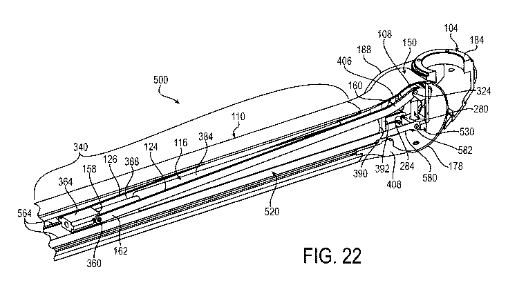
Figs. 21-38 show a load balancing arm 500 according to another
embodiment of the invention. The load balancing arm 500 is in many respects
similar to the above-referenced load balancing arm 100, and consequently the
same reference numerals are used to denote structures corresponding to similar
structures in the load balancing arm 100. In addition, the foregoing
description of
the load balancing arm 100 is equally applicable to the load balancing arm 500
except as noted below. Moreover, it will be appreciated upon reading and
understanding the specification that aspects of the load balancing arms 100,
500
may be substituted for one another or used in conjunction with one another
where
16
CA 03127035 2021-07-16
WO 2020/159618 PCT/US2019/064397
applicable.
Turning then to Figs. 21-38, there is shown a load balancing arm 500 of the
medical device support system 10 in accordance with an embodiment of the
invention. The load balancing arm 500 includes a proximal hub 104, an
adjustable
bearing element 108, a support arm 110, a spring 116, and one or more links,
two
such links 124, 126 in the illustrative embodiment, as shown in Figs. 21-22
and 31-
32. The load balancing arm 500 also includes a distal hub 510 shown in Figs.
21,
23-25, 28 and 37-38, a parallel link 520 shown in Figs. 22, 25, 27-32 and 34-
38, and
a load adjustment base 530 shown in Figs. 22 and 31-33. The proximal hub 104
.. may include a support structure 24 such as the drop tube 24 (see Fig. 1).
The
proximal hub 104 includes a main bearing element 130 that defines a main pivot
axis 132. The adjustable bearing element 108 defines an adjustable pivot axis
142
that is adjustable relative to the main pivot axis 132. The support arm 110
has a
proximal end 150 and a distal end 152. The distal end 152 is pivotably mounted
to
the distal hub 510, which, in turn, is configured to support a medical device
load 36
(see Fig. 1). The proximal end 150 is pivotably mounted to the main bearing
element 130 for pivotable movement about the main pivot axis 132. The
pivotable
movement raises and lowers the height of the medical device load 36 at the
distal
end 152.
The spring 116 extends within a cavity 154 of the support arm 110 and is
mounted to exert a biasing force between the main pivot axis 132 and a distal
end
158 of the spring 116. The links 124, 126 each have a proximal end 160 and a
distal end 162. The proximal end 160 is pivotably mounted to the adjustable
bearing element 108 for pivotable movement about the adjustable pivot axis
142.
The distal ends 162 of the links 124, 126 are pivotably mounted to the distal
end
158 of the spring 116 such that the biasing force exerted by the spring 116 is
transmitted through the links 124, 126 to the adjustable bearing element 108
thereby to generate a moment about the main pivot axis 132 of the proximal hub
104 that counters a moment generated by the medical device load 36 at the
distal
end 152 of the support arm 110, thereby balancing the medical device load 36.
17
CA 03127035 2021-07-16
WO 2020/159618 PCT/US2019/064397
Thus, in the load balancing arm 500 according to the present embodiment,
the links 124, 126 connect at their proximal ends 160 to an adjustment bearing
element 108 and at their distal ends 162 to the distal end 158 of the spring
116. As
will be described in greater detail below, the attachment at the distal end
158 of the
spring 116 allows for a relatively longer link than if connected to the
proximal end of
the spring 116. The inventors have found that this allows for a better force
transmission and less spring travel resulting in a more balanced load
balancing arm
500 throughout the pivotable range of travel of the arm 500.
Reference is now made to Figs. 21-27, 31 and 34-36, which show greater
detail of the support arm 110, the proximal hub 104, and the interface between
the
support arm 110 and proximal hub 104. As shown in Figs. 21-22 and 31, the
proximal end 150 of the support arm 110 has a relatively smaller width than
the
proximal hub 104 and fits within the proximal hub 104. In the illustrated
embodiment, the proximal end 150 of the support arm 110 includes a pair of
vertically oriented laterally spaced protrusions or tongue portions 170 and a
circular
portion 178 substantially surrounding the tongue portions 170. As shown in
Figs.
22, 26 and 31, the proximal hub 104 includes a mounting surface 184 for
mounting
the proximal hub 104 and thus the load balancing arm 100 to, for example, the
distal end of an extension arm 16. The proximal hub 104 includes a pair of
vertically oriented side walls 188 alongside which the tongue portions 170 of
the
support arm 110 slide during adjusting of the support arm 110. In side
profile, the
side walls 188 have a circular shape that corresponds in diameter to the
circular
portion 178 of the proximal end 150 of the support arm 110.
The proximal hub 104 also includes a load adjustment base 530 that extends
width-wise between the pair of vertically oriented side walls 188 and that, as
shown
in Figs. 22, 27 and 34-36 extends vertically downward from a location just
below the
vertically uppermost portion of the circular portion 178 of the proximal end
150 of
the support arm 110 downward approximately three fourths the distance across
the
circular portion 178. Details of one example of the load adjustment base 530
are
shown in Figs. 22, 24-27 and 31-36. As shown in Figs. 26 and 31, the load
18
CA 03127035 2021-07-16
WO 2020/159618 PCT/US2019/064397
adjustment base 530 may be fastened to the side walls 188 by fasteners 198. As
shown in Figs. 26 and 31-33, the load adjustment base 530 has a pair of
laterally
spaced flanges 204 that are recessed inward from the outer width of the load
adjustment base 530. Referring to Fig. 26, the recessed flanges 204 form
respective gaps 210 with the side walls 188 within which the tongue portions
170 of
the support arm 110 are received. As shown in Fig. 26, the tongue portions 170
of
the proximal end 150 of the support arm 110 have through holes 236 and the
main
bearing element 130 of the proximal hub 104 includes a pair of laterally
spaced pins
240. The central axis of these pins 240 defines or coincides with the main
pivot axis
132. The through holes 236 receive the pins 240 thereby to pivotably mount the
proximal end 150 of the support arm 110 to the main bearing element 130 of the
proximal hub 104 for pivotable movement of the support arm 110 about the main
pivot axis 132.
In the illustrative embodiment, bushings 244 are provided on the pins 240 to
promote smooth pivotable operation and serviceability. As shown in Figs. 23,
26
and 31, the pins 240 are fixedly connected, for example by welding, to a
retainer
plate 252, which, in turn, is fastened to the side walls 188 of the proximal
hub 104
by fasteners 258.
As shown in Figs. 22, 27, 32 and 33, a load adjustment screw 280 is
rotatably mounted in a bottom wall 284 of the load adjustment base 530. The
load
adjustment screw 280 is fixed in a vertical orientation in the proximal hub
104 and
rotates about its own central axis 290. Referring to Figs. 1 and 27, in the
present
embodiment, the axis 290 of the load adjustment screw 280 is parallel to an
axis
296 of rotation of the load balancing arm 500 extending centrally through the
.. support structure 24 and perpendicular to horizontal. As shown in Figs. 25-
27 and
32, the adjustable bearing element 108 includes a load adjustment nut 310 that
threadably engages the load adjustment screw 280 to adjust the adjustable
pivot
axis 142 relative to the main pivot axis 132. The load adjustment nut 310
moves in
the vertical direction as the load adjustment screw 280 is rotated, which
vertical
movement adjusts the adjustable pivot axis 142 relative to the main pivot axis
132.
19
CA 03127035 2021-07-16
WO 2020/159618
PCT/US2019/064397
As shown in Figs. 26 and 27, the adjustable bearing element 108 includes a pin
324
that is carried by the load adjustment nut 310. The central axis of the pin
324
defines or coincides with the adjustable pivot axis 142. As shown in Figs. 26,
27
and 32, the proximal ends 160 of the links 124, 126 are pivotably mounted to
the pin
324 at respective opposite ends of the pin 324. The adjustable pivot axis 142
is
adjustable relative to the main pivot axis 132 over a range of adjustment 330,
defined in the illustrative embodiment by the uppermost and lowermost vertical
position of the load adjustment nut 310, as shown in Fig. 32.
The vertical movement of the load adjustment nut 310 adjusts the load
capacity of the load balancing arm 500. As will be appreciated, the distance
between the adjustable pivot axis 142 of the pin 324 and the main pivot axis
132 of
the proximal hub 104 provides the mechanical advantage, or moment, that allows
the load balancing arm 500 to balance a medical device load 36 at the distal
end
152 of the arm 500.
With reference to Fig. 26, the laterally spaced pins 240 split the main pivot
axis 132 thereby enabling the adjustable bearing element 108 to be moved
vertically across the main pivot axis 132 into a position between the
laterally spaced
pins 240. Accordingly, the adjustable bearing element 108 and the proximal
ends
160 of the respective pair of links 124, 126 are movable between the pair of
pins
240 over a portion of the range of adjustment 330. As will be appreciated,
this
provides greater adjustment range in the proximal ends 160 of the links 124,
126
pivotably mounted to the pin 324 of the adjustable bearing element 108 than if
the
pins 240 were a single pin member and the main pivot axis 132 was not split.
Referring to Figs. 26 and 27, the adjustable pivot axis 142 of the adjustable
bearing element 108 and the main pivot axis 132 of the main bearing element
130
are horizontally offset the same distance from the axis 296 of rotation of the
load
balancing arm 500 extending centrally through the support structure 24.
Turning now to Figs. 22, 27 and 34-36, the support arm 110 includes an
intermediate portion 340 between the proximal end 150 and distal end 152 of
the
support arm 110. The intermediate portion 340 has a relatively narrower height
CA 03127035 2021-07-16
WO 2020/159618 PCT/US2019/064397
span than the circular portion 178 of the proximal end 150 of the support arm
110.
The links 124, 126 (only link 124 is in view in Figs. 34-36) have at least one
bend
that corresponds to the difference in height span between the intermediate
portion
340 and the circular portion 178 of the proximal end 150 of the support arm
110. In
the illustrative embodiment, the links 124, 126 have one bend and consequently
have a J-shape in side view. Other shapes such as S-shape (two bends) are also
contemplated. The bend in the links 124, 126 aids in the load balancing arm
500
having a smaller size and lower overall cross section profile than if the
links 124,
126 were straight. The smaller size and lower overall cross section profile
make the
load balancing arm 500 less obstructive in the operating room and improve the
laminar airflow around the surface of the load balancing arm 100.
The distal ends 162 of the links 124, 126 are pivotably mounted to the distal
end 158 of the spring 116 via a carriage slide 364 that is slidable relative
to the
support arm 110. The pivotable connection may be facilitated by, for example,
a pin
360 mounted within the carriage slide 384. As shown in Fig. 29, the carriage
slide
364 is slidable within at least one groove 368 in the support arm 110, wherein
in the
illustrative embodiment there are two such grooves 368 at laterally opposite
sides of
the support arm 110. The grooves 368 are oriented along an axis that extends
radially from and perpendicular to the main pivot axis 132. The grooves 368
are
formed by parallel ribs 370 in the inward facing walls of the support arm 110.
The
ribs 370, along with a horizontal cross beam in the bottom portion of the
support
arm 110, also serve as stiffening members.
The spring 116 of the load balancing arm 500 may be any type of
counterbalancing member, and in the illustrative embodiment is a compression
gas
spring 116. Like the grooves 368, the spring 116 is oriented along an axis
that
extends radially from and perpendicular to the main pivot axis 132. The spring
116
has a cylinder 384 and a rod 388. Referring to Figs. 22, 24, 27 and 32, the
cylinder
384 has a proximal end wall 390 that is coupled to a vertical beam 392 of the
support arm 110. As shown in Fig. 22, the vertical beam 392 extends from a top
wall 406 to a bottom wall 408 of the support arm 110 and is sufficiently
narrow that
21
CA 03127035 2021-07-16
WO 2020/159618 PCT/US2019/064397
the links 124, 126 straddle the vertical beam 392 on opposite lateral sides
thereof
throughout the pivotable range of the load balancing arm 500. The proximal end
wall 390 of the cylinder 384 may be coupled to the vertical beam 392 in any
suitable
manner, for example as by a protrusion 418, shown in Fig. 32, that fits within
an
__ opening 420 in the vertical beam 392, shown in Figs. 24 and 25. The rod 388
is
pivotably mounted to the distal ends 162 of the links 124, 126 via the pin 360
of the
afore described carriage slide 364. In operation, the links 124, 126 straddle
the
spring 116 on laterally opposite sides of the spring 116 throughout the
pivotable
range of the load balancing arm 500.
Figs. 21, 23-25,28 and 37-38 show detail of the distal hub 510 of the load
balancing arm 500. The distal hub 510 is pivotably connected to the distal end
152
of the support arm 110 via a pair of laterally spaced pins 540 held in flanges
of a
vertical block 544 of the distal hub 510. The vertical block 544 can be
fixedly
connected to a pair of vertically oriented side walls 548 of the distal hub
510 in a
__ similar manner that the load adjustment base 530 is connected to the side
walls 188
of the proximal hub 104. Likewise, the distal end 152 of the support arm 110
can
include laterally spaced protrusions 566 that pivotably connect to the
respective
laterally spaced pins 540 in a similar manner that the proximal end
protrusions 170
pivotably connect to the laterally spaced pins 240 of the proximal hub 104.
Figs. 22, 25, 27-32 and 34-38 show detail of the parallel link 520 of the load
balancing arm 500. The illustrative parallel link 520 is a single U-shape link
with two
vertically oriented laterally spaced parallel side walls 564 and a lower
bridge
member 568 connecting the bottom edges of the side walls 564. It will be
appreciated that the parallel link 520 may comprise two parallel links in the
form of
__ the two parallel side walls 564 with the lower bridge member 568 omitted.
Referring
to Figs. 29 and 30, in the present embodiment, the parallel link 520 is made
up of
two pieces, a U-shape stainless steel member 570 and a pair of relatively
harder
stainless steel side braces 572 tack welded to the U-shape stainless steel
member
570.
The parallel link 520 is pivotably connected at its proximal end 580 to a pin
22
CA 03127035 2021-07-16
WO 2020/159618 PCT/US2019/064397
582 supported by the load adjustment base 530 of the proximal hub 104 and at
its
distal end 586 to a pin 588 supported by the vertical block 544 of the distal
hub 510.
As shown in Fig. 35, the split main pivot axis 132, i.e. the laterally spaced
pins 240,
enable the proximal end 580 of the parallel link 520 to move between the pins
240
.. for example when the load balancing arm 500 is pivoted to upper positions.
Likewise, as shown in Figs. 25 and 36, the split pivot axis 590, i.e. the
laterally
spaced pins 540, enable the distal end 586 of the parallel link 520 to move
between
the pins 540 for example when the load balancing arm 500 is pivoted to lower
positions.
As shown in Figs. 27 and 28, the pin 582 is oriented vertically below the pins
240 a distance 600 and the pin 588 is oriented vertically below the pins 540
by the
same distance 600. Also, the horizontal distance between the pins 540 and the
pins 240 at opposite ends of the support arm 110 is equal to the horizontal
distance
between the pin 588 and the pin 582 at opposite ends of the parallel link 520.
In
this way, a parallelogram is formed by the structure of the support arm 110
between
the pins 540 and the pins 240, the portion of the load adjustment base 530
between
the pins 240 and the pin 582, the parallel link 520 between the pin 582 and
the pin
588, and the portion of the vertical block 544 between the pin 588 and the
pins 540.
Referring to Figs. 34-38, owing to this parallelogram linkage, the vertically
aligned
pins 540, 588 at the distal end 152 remain parallel to the vertically aligned
pins 240,
582 at the proximal end 150 throughout the pivotable range of the load
balancing
arm 500 about the main pivot axis 132. This permits a medical device load 36
such
as a monitor to remain properly oriented regardless of its vertical
displacement from
the ceiling of the operating room.
Referring now to Figs. 22, 25, 26, 31 and 32, the side walls 564 of the
parallel link 520 straddle the vertically lower portion of the gas spring 116
on
laterally opposite sides thereof. The side walls 564 also straddle the links
124, 126
on laterally opposite sides of the links 124, 126 over at least a portion of
the
pivotable range of the load adjustment arm 500, particularly when the
adjustable
bearing element 108 is in lower positions as shown in Fig. 24.
23
CA 03127035 2021-07-16
WO 2020/159618 PCT/US2019/064397
Reference is now made to Figs. 34-36, which show the load balancing arm
500 in three different vertical positions, and Figs. 37 and 38, which show the
parallel
link 520 and the distal end 152 of the support arm 110 relative to the distal
hub 510
in the respective uppermost and lowermost vertical positions. The links 124,
126
are shown adjusted to their maximum height in Figs. 34-36, thereby maximizing
the
moment, or mechanical advantage, of the load balancing arm 500. In Fig. 34,
the
support arm 110 is in a substantially horizontal position. In Figs. 35 and 37,
the
support arm 110 is shown pivoted about the main pivot axis 132 about 40
degrees
upward relative to horizontal. In Figs. 36 and 38, the support arm 110 is
shown
pivoted about the main pivot axis 132 about 40 degrees downward from
horizontal.
As will be appreciated, then, the support arm 110 has an angle of rotation
about the
main pivot axis 132 of about 40 degrees upward from horizontal to about 40
degrees downward from horizontal.
Figs. 39-45 show a load adjustment base 600 and an adjustable bearing
element 602 according to another embodiment of the invention. The load
adjustment base 600 and adjustable bearing element 602 are in many respects
similar to the above-referenced load adjustment bases 196, 530 and adjustable
bearing elements 108 shown for example in Figs. 12-14, 20, 26 and 31-33, and
consequently the same reference numerals are used in Figs. 39-45 to denote
structures corresponding to similar structures in the load adjustment bases
196, 530
and adjustable bearing elements 108. In addition, the foregoing description of
the
load adjustment bases 196, 530 and adjustable bearing elements 108 is equally
applicable to the load adjustment base 600 and the adjustable bearing element
602
except as noted below. Moreover, it will be appreciated upon reading and
understanding the specification that aspects of the load adjustment bases 196,
530,
600 may be substituted for one another or used in conjunction with one another
where applicable, and aspects of the adjustable bearing elements 108, 602 may
be
substituted for one another or used in conjunction with one another where
applicable.
Turning to Figs. 39-45, the load adjustment base 600 and the adjustable
24
CA 03127035 2021-07-16
WO 2020/159618 PCT/US2019/064397
bearing element 602 are configured to enable a specific range of adjustment of
the
adjustable pivot axis 142 of the adjustable bearing element 108 relative to
the main
pivot axis 132 of the proximal hub 104. As shown in Figs. 40, 42 and 44, a
pair of
socket head cap screws 610, 612 are provided in respective threaded openings
in a
rear wall 624 of the load adjustment base 600. As shown in Figs. 40 and 45,
the
centers of the screws 610, 612 are laterally spaced apart a distance X in a
direction
parallel to the main pivot axis 132, and vertically spaced apart a distance Y
in a
direction perpendicular to the main pivot axis 132. As shown in Figs. 41 and
44, a
pair of vertically extending slots 640, 642 are provided in a load adjustment
nut 650
of the adjustable bearing element 602. The lateral spacing between the
vertically
extending slots 640, 642 is equal to the lateral spacing Y between the centers
of the
screws 610, 612. In the illustrative embodiment, the screws 610, 612 and slots
640,
642 are on laterally opposite sides of the central axis 290 of the load
adjustment
screw 280.
The tips 660, 662 of the respective socket head cap screws 610, 612
protrude forward from the rear wall 624 and are sized to fit within the
respective
slots 640, 642. One slot 640 has a lower abutment wall 670 and opens upward at
a
top surface 674 of the load adjustment nut 650 to define a vertical
entranceway 680
for the screw 610. The other slot 642 has an upper abutment wall 672 and opens
downward at a bottom surface 676 of the load adjustment nut 650 to define a
vertical entranceway 682 for the screw 612. The lower and upper abutment walls
670, 672 of the load adjustment nut 650 define the respective upper and lower
limits
on the range of adjustment of the load adjustment nut 650, and thus, in
reference to
Figs. 9, 12, 26, 31 and 32, the upper and lower limits on the range of
adjustment of
the pin 324 to which the proximal ends 160 of the links 124, 126 are pivotably
mounted. This contrasts with the upper limit of the range of adjustment 330
being
defined by a top wall of the load adjustment base 196, 530 or an end-of-thread
of
the load adjustment screw 280, and the lower limit being defined by the bottom
wall
284 of the load adjustment base 196, 530.
Thus, as the load adjustment nut 650 moves up and down in the vertical
CA 03127035 2021-07-16
WO 2020/159618 PCT/US2019/064397
direction as the load adjustment screw 280 is rotated respectively clockwise
and
counterclockwise, the adjustable pivot axis 142 moves vertically up and down
relative to the main pivot axis 132 bound by the respective upper and lower
limits on
the adjustment range provided by the abutment walls 670, 672 of the load
adjustment nut 650. Figs. 43 and 44 show an example of the lower limit. As
will
appreciated with reference to Fig. 44, as the load adjustment nut 650 is urged
downward, the upper abutment wall 672 of slot 642 eventually abuts the tip 662
of
the socket head cap screw 612 thereby preventing further downward movement of
the load adjustment nut 650. As will be appreciated, in a similar manner, as
the
load adjustment nut 650 is urged upward, the lower abutment wall 670 of the
slot
640 eventually abuts the tip 660 of the screw 610 to prevent further upward
movement of the load adjustment nut 650.
The Figs. 39-45 embodiment enables a specific range of adjustment of the
adjustable pivot axis 142 relative to the main pivot axis 132. For example, by
adjusting the lengths of the slots 640, 642 and/or the positions of the upper
and
lower abutment walls 670, 672, the range of adjustment can be changed without
having to change the structure of the load adjustment base 600. In the
illustrative
embodiment, for example, the lower abutment location, L, is vertically above
the
topmost portions of the diameters of the openings 690 that accommodate the
laterally spaced pins 240 that form the main bearing element 130 (see Figs. 12
and
31) that defines the main pivot axis 132. When the upper abutment wall 672 has
abutted the socket head cap screw 612, the load adjustment nut 650 has reached
its lowermost position or "bottomed out" but a clearance gap, C, remains
between
the bottom surface 694 of the load adjustment nut 650 and the bottom wall 684
of
the load adjustment base 600.
It will be appreciated that the quantity of socket head cap screws 610, 612
and corresponding quantity of slots 640, 642 need not be limited to two as
shown.
For example, a second pair of socket head cap screws and a second pair of
slots
further laterally spaced apart than the first pair of socket head cap screws
610, 612
and the first pair of slots 640, 642, for a total of four socket head cap
screws and
26
CA 03127035 2021-07-16
WO 2020/159618 PCT/US2019/064397
four slots, can be provided, where the second pair of socket head cap screws
and
second pair of slots define a different upper and lower limit on the range of
adjustment than that of the first pair of socket head cap screws 610, 612 and
first
pair of slots 640, 642. It will also be appreciated that the rear wall 624 of
the load
adjustment base 600 may include a plurality of vertically staggered threaded
openings to allow the vertical height of the screws 610, 612 to be changed,
thus
allowing the corresponding range of adjustment of the adjustable pivot axis
142
relative to the main pivot axis 132 to be changed. It will also be appreciated
that
either the upper adjustment limit mechanism 610, 640, 670 or the lower
adjustment
limit mechanism 612, 642, 672 may be omitted and a different limit mechanism
substituted therefor; for example, substituting a top wall of the load
adjustment base
196, 530 or an end-of-thread of the load adjustment screw 280 for the upper
adjustment limit mechanism 610, 640, 670, and/or substituting the bottom wall
284
of the load adjustment base 196, 530 for the lower adjustment limit mechanism
612,
642, 672. Other combinations are also contemplated. It will further be
appreciated
that protruding elements other than socket head cap screws 610, 612 may be
used
to fit within the slots 640, 642 to act as limits to the respective abutment
walls 670,
672 of the adjustable bearing element 602. For example, rather than socket
head
cap screws 610, 612 being inserted in respective threaded openings in the rear
wall
624 of the load adjustment base 600, clips may be inserted through respective
through holes in the rear wall 624, wherein the tips of the clips act as the
limits to
the respective abutment walls 670, 672.
Although the invention has been shown and described with respect to a
certain embodiment or embodiments, it is obvious that equivalent alterations
and
modifications will occur to others skilled in the art upon the reading and
understanding of this specification and the annexed drawings. In particular
regard
to the various functions performed by the above described elements
(components,
assemblies, devices, compositions, etc.), the terms (including a reference to
a
"means") used to describe such elements are intended to correspond, unless
otherwise indicated, to any element which performs the specified function of
the
27
CA 03127035 2021-07-16
WO 2020/159618 PCT/US2019/064397
described element (i.e., that is functionally equivalent), even though not
structurally
equivalent to the disclosed structure which performs the function in the
herein
illustrated exemplary embodiment or embodiments of the invention. In addition,
while a particular feature of the invention may have been described above with
respect to only one or more of several illustrated embodiments, such feature
may
be combined with one or more other features of the other embodiments, as may
be
desired and advantageous for any given or particular application.
28