Note: Descriptions are shown in the official language in which they were submitted.
CA 03127089 2021-07-16
WO 2020/150565 PCT/US2020/014013
-1-
SYSTEMS AND METHODS TO LOCALIZE A RECREATIONAL TRAILER
CROSS-REFERENCE TO RELATED APPLICATIONS
[0001] The present specification claims priority to U.S. Provisional
Application
No. 62/794,318, filed January 18, 2019, entitled "SYSTEMS AND METHODS TO
LOCALIZE A RECREATIONAL VEHICLE," the entirety of which is incorporated by
reference herein.
BACKGROUND
[0002] Recreational trailers may temporarily couple to a vehicle to be
moved from
one location to another. By their nature, recreational trailers are stored or
left at a particular
location for an extended period of time. Often, the extended period of time is
when the
recreational trailers are left or stored without supervision from their owner.
As such,
recreational trailers are often subject to theft. To assist in knowing when an
unauthorized
movement of the recreational trailer is occurring and/or to assist in tracking
the unauthorized
movement of the recreational trailer, systems and methods for tracking the
recreational
trailer may be utilized.
[0003] Accordingly, a need exists for systems and methods for localizing
recreational trailers.
SUMMARY
[0004] In an embodiment, a trailer localizing system comprises a tow
vehicle, a
trailer configured to be coupled to the tow vehicle for towing by the tow
vehicle, a memory,
and machine readable instructions stored in the memory. The trailer comprises
a plurality
of solar panels, a location determination device, a tracking device
communicatively coupled
with the location determination device to transmit a current real time
position of the trailer
when the tracking device is active, and an electronic control unit
communicatively coupled
to the plurality of solar panels, the tracking device, and the location
determination device.
The memory is communicatively coupled to the electronic control unit. The
machine
readable instructions cause the trailer localizing system to perform at least
the following
CA 03127089 2021-07-16
WO 2020/150565 PCT/US2020/014013
-2-
when executed by the electronic control unit: determine by the electronic
control unit
whether the trailer is electronically connected to the tow vehicle, determine
whether the
plurality of solar panels are active upon a determination that the trailer is
not electrically
connected to the tow vehicle, activate the tracking device along with the
location
determination device upon a determination that the trailer is electronically
connected to the
tow vehicle, the plurality of solar panels are active, or both, generate an
alert that the tracking
device is active upon activation of the tracking device, and transmit the
current real time
position of the trailer with the alert to track the trailer.
[0005] In another embodiment, a trailer localizing system comprises a tow
vehicle,
a trailer, a memory, and machine readable instructions stored in the memory.
The trailer is
configured to be coupled to the tow vehicle for towing by the tow vehicle and
comprises a
plurality of solar panels, a location determination device, a tracking device
communicatively
coupled with the location determination device to transmit a current real time
position of the
trailer when the tracking device is active, and an electronic control unit
communicatively
coupled to the plurality of solar panels, the tracking device, and the
location determination
device. The memory is communicatively coupled to the electronic control unit,
and the
machine readable instructions cause the trailer localizing system to perform
at least the
following when executed by the electronic control unit: determine by the
electronic control
unit whether the trailer is electronically connected to the tow vehicle,
determine whether the
plurality of solar panels are active upon a determination that the trailer is
not electrically
connected to the tow vehicle, determine by the electronic control unit whether
a wheel of
the trailer is rotating at a wheel speed that is above a threshold speed, and
activate the
tracking device along with the location determination device upon a
determination that the
trailer is electronically connected to the tow vehicle, the plurality of solar
panels are active,
the wheel of the trailer is rotating at the wheel speed that is above the
threshold speed, or
combinations thereof. The machine readable instructions further cause the
trailer localizing
system to perform at least the following when executed by the electronic
control unit:
generate an alert that the tracking device is active upon activation of the
tracking device,
wherein the alert is configured to prompt a user to indicate whether movement
of the trailer
is authorized, and transmit the current real time position of the trailer with
the alert to track
the trailer.
[0006] In one other embodiment is a method of tracking a trailer
configured to be
CA 03127089 2021-07-16
WO 2020/150565 PCT/US2020/014013
-3-
coupled to a tow vehicle for towing by the tow vehicle. The trailer comprises
a plurality of
solar panels, a location determination device, a tracking device
communicatively coupled
with the location determination device to transmit a current real time
position of the trailer
when the tracking device is active, and an electronic control unit
communicatively coupled
to the plurality of solar panels, the tracking device, and the location
determination device.
The method comprises determining by the electronic control unit whether the
trailer is
electronically connected to the tow vehicle, determining whether the plurality
of solar panels
are active upon a determination that the trailer is not electrically connected
to the tow
vehicle, and activating the tracking device along with the location
determination device
upon a determination that the trailer is electronically connected to the tow
vehicle, the
plurality of solar panels are active, or both. The method further comprises
generating an
alert that the tracking device is active upon activation of the tracking
device, and
transmitting the current real time position of the trailer with the alert to
track the trailer.
[0007] These and additional features provided by the embodiments
described herein
will be more fully understood in view of the following detailed description,
in conjunction
with the drawings.
BRIEF DESCRIPTION OF THE DRAWINGS
[0008] The embodiments set forth in the drawings are illustrative and
exemplary in
nature and not intended to limit the disclosure. The following detailed
description of the
illustrative embodiments can be understood when read in conjunction with the
following
drawings, where like structure is indicated with like reference numerals and
in which:
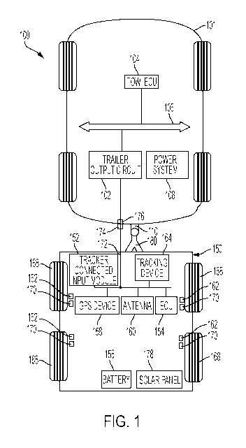
[0009] FIG. 1 schematically depicts a vehicle and a recreational trailer
having a
trailer localizing system, according to one or more embodiments shown and
described
herein;
[0010] FIG. 2A schematically depicts illustrative hardware components of
an
electronic control unit that may be used in the trailer localizing system
according to one or
more embodiments shown and described herein;
CA 03127089 2021-07-16
WO 2020/150565 PCT/US2020/014013
-4-
[0011] FIG. 2B schematically depicts an illustrative memory component
containing
illustrative logic components according to one or more embodiments shown and
described
herein;
[0012] FIG. 2C schematically depicts an illustrative data storage device
containing
illustrative data components according to one or more embodiments shown and
described
herein;
[0013] FIG. 3 schematically depicts a flowchart of an exemplary method
for
localizing a trailer, according to one or more embodiments shown and described
herein; and
[0014] FIG. 4 schematically depicts a flowchart of an exemplary method
for
localizing a trailer and enabling a trailer brake, according to one or more
embodiments
shown and described herein.
DETAILED DESCRIPTION
[0015] The embodiments disclosed herein include systems and methods for
localizing, or tracking, a recreational trailer while the trailer is moving.
This movement
may be authorized or unauthorized. Referring generally to the figures, an
electronic control
unit ("ECU") configured to localize or track the recreational trailer is
provided. The ECU
is disposed within the recreational trailer and is in communication with a
tracking device, a
GPS device, an antenna, and/or the like. The ECU is configured to enable the
tracking
device, the GPS device and the localizing software whenever the recreation
trailer is in
electrical communication with a tow vehicle. The electrical communication may
be by
connecting a female electrical connector of the recreational trailer to a male
electrical
connector of the vehicle, such as those generally associated with 4-way and 7-
way
connectors. When there is an electrical connection between the recreational
trailer and the
tow vehicle, the ECU establishes a tracking beacon, a localization beacon, or
a plurality of
tracking information that monitors the recreational trailer position. The ECU
may transmit
a current location, in real-time, of the recreational trailer. Further, when
the ECU establishes
the tracking beacon based on the electrical connection between the
recreational trailer and
the vehicle, the ECU and the tracking beacon cannot be manually overridden. In
some
embodiments, the tracking information is transmitted to a predetermined
personal electronic
device such as a mobile phone or a laptop. Further, in these embodiments, an
owner or user
CA 03127089 2021-07-16
WO 2020/150565 PCT/US2020/014013
-5-
may elect to indicate that the recreational trailer has unauthorized movement.
In some
embodiments, the recreational trailer further includes wheel sensors that are
configured to
detect a wheel speed of the trailer. In this embodiment, when the user
indicates that the
recreational trailer has unauthorized movement, the trailer brakes may be
applied by the
ECU to lock the recreational trailer when the recreational trailer is at a
stopped condition.
The various systems and methods for localizing the recreational trailer during
movement of
the recreational trailer will be described in more detail herein with specific
reference to the
corresponding drawings.
[0016] The phrase "communicatively coupled" is used herein to describe
the
interconnectivity of various components of the tracking system and means that
the
components are connected either through wires, optical fibers, or wirelessly
such that
electrical, optical, and/or electromagnetic signals may be exchanged between
the
components. As such, coupled components are capable of exchanging data signals
with one
another such as, for example, electrical signals via conductive medium,
electromagnetic
signals via air, optical signals via optical waveguides, and the like. It
should be understood
that other means of connecting the various components of the system not
specifically
described herein are included without departing from the scope of the present
disclosure.
[0017] Additionally, it is noted that the term "signal" means a waveform
(e.g.,
electrical, optical, magnetic, mechanical or electromagnetic), such as DC, AC,
sinusoidal-
wave, triangular-wave, square-wave, vibration, and the like, capable of
traveling through a
medium.
[0018] Referring now to FIG. 1, a trailer localizing system 100 is
schematically
depicted. In one embodiment, an exemplary tow vehicle 101 is coupled to and
operable to
tow an exemplary trailer 150. The trailer 150 may be any trailer capable of
having the
components as described herein and capable of being towed by the tow vehicle
101. By
way of non-limiting example, in some embodiments, the exemplary trailer 150
may be a
recreational trailer. In other embodiments, the exemplary trailer 150 may be a
pop-up
camper trailer, a travel trailers, a cargo trailer such as a snowmobile
trailer, a motorcycle
trailer, and a bicycle trailer, a utility trailer, a dump trailer, a semi or a
full trailer, a livestock
trailer, and/or the like.
CA 03127089 2021-07-16
WO 2020/150565 PCT/US2020/014013
-6-
[0019] The trailer 150 includes a trailer connected input module 152, an
electronic
control unit ("ECU") 154, a battery 156, a location determination device 158
(e.g., a global
position system ("GPS") and/or global navigation satellite system ("GNSS")),
an antenna
160, a plurality of wheel speed sensors 162, a tracking device 164, and a
communication
path 166. The various components of the tow vehicle 101 and the interaction
thereof will
be described in detail below.
[0020] The trailer 150 further includes a plurality of trailer wheels
168, each trailer
wheel 168 having at least one trailer brake 170 and the at least one wheel
speed sensor 162.
As depicted in FIG. 1, the trailer 150 includes four trailer brakes 170, one
for each trailer
wheel 168 and four separate speed sensors of the wheel speed sensors 162, one
coupled to
each trailer wheel 168. However, it should be understood that in other
embodiments, the
trailer 150 may include more than or less than four trailer brakes 170 and/or
wheel speed
sensors 162.
[0021] Still referring to FIG. 1, the trailer connected input module 152
is
communicatively coupled to the communication path 166, to the tracking device
164, to the
ECU 154, and to the location determination device 158. The trailer connected
input module
152 is configured to detect when the trailer 150 is electrically coupled to
the tow vehicle
101. The trailer connected input module 152 may be configured to detect a
signal, a closed
circuit current, a closed circuit voltage, and/or the like when the trailer
150 is electrically
coupled to the tow vehicle 101. It should be appreciated that the electric
coupling between
the trailer 150 and the tow vehicle 101 may be by a connector such as a four-
way connector,
a seven-way connector, and/or the like. The trailer 150 is configured to be
electronically
connected to the tow vehicle 101 through an electrical coupling comprising the
connector
as an electrical connector. Generally, the trailer 150 has a pigtail
containing a first connector
174 (as one of a female connector and a male connector) specifically
configured to mate
with a second connector 176 (as the other of the female connector and the male
connector)
embedded within the tow vehicle 101. As such, when the connectors 174, 176 are
electrically coupled, the trailer connected input module 152 may detect this
coupling by
detecting the signal, the closed circuit current, the closed circuit voltage,
and/or the like
transmitted from the tow vehicle 101 to the trailer 150. In some embodiments,
the trailer
connected input module 152 may alert other components of the trailer 150, such
as the ECU
154, the tracking device 164, the location determination device 158, and/or
the like via a
CA 03127089 2021-07-16
WO 2020/150565 PCT/US2020/014013
-7-
signal that indicates that the trailer 150 is electrically coupled to the tow
vehicle 101. FIG.
1 illustrates that the trailer 150 is electrically coupled to the tow vehicle
101 via the pigtail
having the first connector 174 mating to the second connector 176 thereby
creating an
electrical connection 172 between the tow vehicle 101 and the trailer 150.
[0022] In some embodiments, the trailer connected input module 152 may
act as an
interface between the ECU 154 and other components, such as the location
determination
device 158, other navigation systems, meter units of a vehicle, mobile phone
systems,
infotainment systems, and/or the like. In other embodiments, the trailer
connected input
module 152 may be utilized to transmit one or more commands to the other
components of
the trailer 150.
[0023] In some embodiments, the trailer connected input module 152 may
determine
when a connection between the tow vehicle 101 and the trailer 150 exists or is
disrupted
based on a camera mounted to the trailer 150 and object recognition software
that may use
machine learning to determine whether the trailer 150 is connected to the tow
vehicle 101.
In other embodiments, a receiver hitch 180 of the trailer 150 may include a
plurality of
sensors, switches, and/or the like, that monitor and transmit a signal when
the trailer 150 is
attached to the tow vehicle 101 (i.e., sensors positioned to determine when a
lock of the
receiver hitch 180 is in use, sensors positioned to determine when a ball of a
hitch 110 is
within the receiver hitch 180, and/or the like).
[0024] The location determination device 158 may be communicatively
coupled to
the ECU 154, the trailer connected input module 152, and the tracking device
164 by the
communication path 166. The location determination device 158 may be any
device capable
of providing a plurality of signals and/or communicating with components, such
as the
antenna 160, the tracking device 164, and the ECU 154 for the purposes of, in
real-time,
localizing or tracking the trailer 150, triangulating the trailer 150
position, and/or the like.
The location determination device 158 may be any commercially available device
capable
of determining, transmitting, or receiving a position or a triangulation with
respect to
location or position services associated with the trailer 150. As a non-
limiting example, the
location determination device 158 may be a Garmin, Tile, Spot, and/or the
like. Further, it
should be appreciated that the battery 156 may be a battery backup for the
location
determination device 158. As such, in the event the event the battery 156
dies, then the
CA 03127089 2021-07-16
WO 2020/150565 PCT/US2020/014013
-8-
location determination device 158 may shutdown, but will restart once either
there is
sufficient solar power available to recharge the battery 156 to where the
location
determination device 158 has ample power to restart or when the first
connector 174 is mated
with the second connector 176, which results in the battery 156 receiving
power from the
tow vehicle 101, as discussed in greater detail herein.
[0025] The antenna 160 may be any device configured to work with global
positioning systems ("GPS"), the location determination device 158, the
tracking device
164, the network interface hardware 208 (FIG. 2A), other navigation systems,
and/or the
like. As such, the antenna 160 may be suitable for receiving signals, such as
GPS signals,
signals from a user via a mobile device through the network interface hardware
208 (FIG.
2A), and/or the like. As a non-limiting example, the antenna 160 may be a
Lowrance,
Simrad, Proxicast, and/or the like.
[0026] The tracking device 164 is communicatively coupled to the ECU 154,
the
location determination device 158, the trailer connected input module 152, and
the antenna
160. The tracking device 164 is configured to pair with, or work in
conjunction with the
location determination device 158 and the antenna 160 so to transmit the
current real time
positioning or location of the trailer 150 when the tracking device 164 is
active. It should
be appreciated that the tracking and/or transmitting of the current real time
location of the
trailer 150 may be via geopositioning an object, geofencing, using radio
frequency, satellite
navigation, radiolocation, and/or the like. In some embodiments, the tracking
device 164 is
configured to pair with or work in conjunction with the location determination
device 158
and the antenna 160 so to triangulate and transmit the current real time
positioning or
location of the trailer 150 when the tracking device 164 is active. It should
be appreciated
that the triangulation may be via radio frequencies such as Wi-Fi, a hot spot,
or other wired
and/or wireless communications.
[0027] The tracking device 164 may be configured to be operable by a
switch such
as a two-position key switch, a two-position toggle switch, a push button
switch,
electronically switched through the ECU 154, and/or the like. The two-position
key switch
may be a physical switch that is either in the off position or the on
position. The two-
position toggle switch may be a physical switch that is either in the off
position or the on
position. The push button switch may be a physical switch that toggles between
the off and
CA 03127089 2021-07-16
WO 2020/150565 PCT/US2020/014013
-9-
on positions based on a number of presses on the push button or any other
pattern. It should
be appreciated that any of the physical switches may be disposed within or
external to the
trailer 150. The electronic switch may be remotely turned on and off through
an electronic
device such as a mobile phone, laptop, and/or the like. The electronic switch
may work
with an application or other software to communicate with the ECU 154 as
explained in
greater detail herein. In operation, when the trailer 150 is connected to the
tow vehicle 101,
such that the first connector 174 is electrically coupled to the second
connector 176 of the
tow vehicle 101 so to form the electrical connection 172, is recognized by, or
alerts the
trailer connected input module 152. In turn, the trailer connected input
module 152 alerts
the ECU 154, and/or other components of the trailer 150. The ECU 154 may then
activate
the tracking device 164 regardless of whether the tracking device 164 has
manually been
placed or switched into the off position, as discussed in further detail
herein.
[0028] The trailer 150 further includes a battery 156. The battery 156 is
operably
connected to the trailer 150. As such, the battery may power the ECU 154, the
location
determination device 158, the antenna 160, the trailer connected input module
152, the
tracking device 164 and/or the like. In some embodiments, the battery 156 may
also power
other components of the trailer 150 such as internal lighting, appliances,
radio, television,
and/or the like whether or not the trailer 150 is connected to the tow vehicle
101 through the
electrical connection 172.
[0029] In some embodiments, the trailer 150 may further include a
plurality of solar
panels 178. The plurality of solar panels 178 is operably connected to the
trailer 150 and
may be configured to power the ECU 154, the location determination device 158,
the
antenna 160, the trailer connected input module 152, the tracking device 164,
and/or the
like. In some embodiments, the plurality of solar panels 178 may also power
other
components of the trailer 150 such as internal lighting, appliances, radio,
television, and/or
the like whether or not the trailer 150 is connected to the tow vehicle 101
through the
electrical connection 172. Moreover, in some embodiments, the plurality of
solar panels
178 may be manually activated so to switch the trailer 150 from the battery
156 as a source
of power to the plurality of solar panels 178 as the source of power.
[0030] The manual activation may be via a physical switch disposed within
the
trailer 150 and/or remotely via the application accessed by the personal
electronic device.
CA 03127089 2021-07-16
WO 2020/150565 PCT/US2020/014013
-10-
In other embodiments, the plurality of solar panels 178 may be used to
recharge the battery
156 before, during, and/or after using the battery 156 as a source of power.
In still other
embodiments, the trailer localizing system 100 may switch between the battery
156 as a
source of power and the plurality of solar panels as a source of power or as a
battery charger
when the battery 156 charge level is equal to or below a predetermined
threshold so as to
not completely remove the charge of the battery 156. It should be appreciated
that it may
be necessary to keep the battery charged so to continuously transmit the
location or position
of the trailer 150, whether or not electrically coupled to the tow vehicle
101, using the
various components of the trailer as discussed herein. In some embodiments,
when the
trailer localizing system 100 is utilizing the plurality of solar panels 178,
the ECU 154 is
alerted to the plurality of solar panels 178 use, which may activate the
tracking device 164
regardless of whether the tracking device 164 has manually been placed or
switched into the
off position, as discussed in further detail herein. As such, in some
embodiments, the user
may utilize the plurality of solar panels 178 to localize the trailer. In a
nonlimiting example,
the user may not remember or be able to find the trailer 150 in a large RV
park, storage area,
and/or the like. As such, because the plurality of solar panels 178 are
active, the trailer
localizing system 100 is also active so that the user may be alerted to the
location of the
trailer 150, as discussed in further detail herein.
[0031] Still referring to FIG. 1, the tow vehicle 101 may be an
automobile or any
other passenger or non-passenger vehicle such as, for example, a pick-up truck
or a tractor
truck. The tow vehicle 101 includes a trailer output circuit 102 and a tow
electronic control
unit ("tow ECU") 104, both in communication with one another via a
communication link
106. The towing vehicle further includes the second connector 176
communicatively
coupled to the trailer output circuit 102. The various components of the tow
vehicle 101
and the interaction thereof will be described in detail below.
[0032] Still referring to FIG. 1, the communication link 106 may be
formed from
any medium that is capable of transmitting a signal such as, for example,
conductive wires,
conductive traces, optical waveguides, or the like. Moreover, the
communication link 106
may be formed from a combination of mediums capable of transmitting signals.
In one
embodiment, the communication link 106 comprises a combination of conductive
traces,
conductive wires, connectors, and buses that cooperate to permit the
transmission of
electrical data signals to components such as processors, memories, sensors,
input devices,
CA 03127089 2021-07-16
WO 2020/150565 PCT/US2020/014013
- 11 -
output devices, and communication devices. Accordingly, the communication link
106 may
comprise a towing vehicle bus, such as for example a LIN bus, a CAN bus, a VAN
bus, and
the like. The communication link 106 communicatively couples the various
components of
the tow vehicle 101.
[0033] The trailer output circuit 102 is communicatively coupled to the
tow ECU
104. The trailer output circuit 102 is electrically coupled to one or more
components of the
trailer 150 by a conductive medium, such as the second connector 176. The
trailer output
circuit 102 is controlled by the tow ECU 104 and supplies an electrical
trailer output signal,
current, and/or voltage via the second connector 176 through the pigtail with
the first
connector 174 and into the trailer connected input module 152 of the trailer
150. The trailer
output circuit 102 may create the electrical connection 172 to electrically
couple the tow
vehicle 101 to the trailer 150. In some embodiments, the trailer output
circuit 102 may
supply a signal and/or a current from a power system 108 of the tow vehicle
101. As such,
this supplied current may power a number of components of the trailer 150 such
as external
lights (i.e., running lights, brake lights, and turn signal lights), the
trailer connected input
module 152, the location determination device 158, the tracking device 164,
the ECU 154,
the antenna 160, the wheel speed sensors 162, and/or the trailer brakes 170.
[0034] Now referring to FIG. 2A, a schematic depiction of illustrative
hardware
components of the trailer 150 that may be used in the trailer localizing
system 100 will now
be described. While the components depicted in FIG. 2A are described with
respect to the
trailer 150, it should be understood that similar components may also be used
outside or
external to the trailer 150 without departing from the scope of the present
disclosure.
[0035] The ECU 154 may have a non-transitory computer-readable medium for
completing the various processes described herein, embodied as hardware,
software, and/or
firmware, according to embodiments shown and described herein. While in some
embodiments the ECU 154 may be configured as a general purpose computer with
the
requisite hardware, software, and/or firmware, in other embodiments, the ECU
154 may
also be configured as a special purpose computer designed specifically for
performing the
functionality described herein. For example, the ECU 154 may be a device that
is
particularly adapted to activate a localization system configured for
determining or tracking
a location, in real-time, of the trailer 150 and transmitting the location to
an external device
CA 03127089 2021-07-16
WO 2020/150565 PCT/US2020/014013
-12-
such as a mobile electronic device. In another example, the ECU 154 may be a
device that
is particularly adapted to utilize the wheel speed sensors 162 for the
purposes of monitoring
the trailer conditions, monitoring the trailer 150 for having movement that
may or may not
be authorized, and executing commands to the other components of the trailer
150 such as
the trailer brakes 170 to stop or inhibit movement of the trailer 150. In
embodiments where
the ECU 154 is a general purpose computer, the systems and methods described
herein
provide a mechanism for improving functionality by providing a localization or
tracking
device that is kept active when there is an electrical connection between the
trailer 150 and
the tow vehicle 101 and providing a real time visual display of the trailer
150 to a user.
[0036] Now referring to FIG. 2A, the ECU 154 may generally be an onboard
computing system. In some embodiments, the ECU 154 may be a plurality of
vehicle
computing systems. The ECU 154 may include a processor 204, an I/O hardware
206, a
network interface hardware 208, a non-transitory memory 210, a system
interface 212, and
data storage device 214. A local interface 202, such as a bus or the like, may
interconnect
the various components. The processor 204, such as a computer processing unit
(CPU),
may be the central processing unit of the ECU 154, performing calculations and
logic
operations to execute a program. The processor 204, alone or in conjunction
with the other
components, is an illustrative processing device, computing device, or
combination thereof.
The processor 204 may include any processing component configured to receive
and
execute instructions (such as from the data storage device 214 and/or the
memory 210).
[0037] Still referring to FIG. 2A, the memory 210 may be configured as a
volatile
and/or a nonvolatile computer-readable medium and, as such, may include random
access
memory (including SRAM, DRAM, and/or other types of random access memory),
read
only memory (ROM), flash memory, registers, compact discs (CD), digital
versatile discs
(DVD), and/or other types of storage components. The memory 210 may include
one or
more programming instructions thereon that, when executed by the processor
204, cause the
processor 204 to complete various processes, such as the processes described
herein with
respect to FIGS. 3-4. Still referring to FIG. 2A, the programming instructions
stored on the
memory 210 may be embodied as a plurality of software logic modules, where
each logic
module provides programming instructions for completing one or more tasks, as
described
in greater detail below with respect to FIG. 2B.
CA 03127089 2021-07-16
WO 2020/150565 PCT/US2020/014013
-13-
[0038] The I/O hardware 206 may communicate information between the local
interface 202 and one or more other components of the tow vehicle 101. For
example, the
I/O hardware 206 may act as an interface between the ECU 154 and other
components, such
as the location determination device 158, other navigation systems, vehicle
meter units,
mobile phone systems, infotainment systems, and/or the like. In some
embodiments, the
I/O hardware 206 may be utilized to transmit one or more commands to the other
components of the trailer 150. Further, the I/O hardware 206 may receive
inputs from the
wheel speed sensors 162 or the pigtail having the first connector 174.
[0039] The network interface hardware 208 may include any wired or
wireless
networking hardware, such as a modem, a LAN port, a wireless fidelity (Wi-Fi)
card,
WiMax card, mobile communications hardware, and/or other hardware for
communicating
with other networks and/or devices. For example, the network interface
hardware can
include a chipset (e.g., antenna, processors, machine readable instructions,
etc.) to
communicate over wired and/or wireless computer networks such as, for example,
wireless
fidelity (Wi-Fi), WiMax, Bluetooth, IrDA, Wireless USB, Z-Wave, ZigBee, or the
like. The
network interface hardware 208 may provide a communications link between the
trailer 150
and the other networks using the antenna 160 so to connect to, without
limitation, Google
Maps, Waze, the user's electronic mobile device, and/or the like.
[0040] The system interface 212 may generally provide the ECU 154 with an
ability
to interface with one or more external devices such as, for example, the
mobile electronic
device. Communication with external devices may occur using various
communication
ports, wirelessly, and/or the like.
[0041] Still referring to FIG. 2A, the data storage device 214, which may
generally
be a storage medium, may contain one or more data repositories for storing
data that is
received and/or generated. The data storage device 214 may be any physical
storage
medium, including, but not limited to, a hard disk drive (HDD), memory,
removable storage,
and/or the like. While the data storage device 214 is depicted as a local
device, it should be
understood that the data storage device 214 may be a remote storage device,
such as, for
example, a server-computing device or the like. Illustrative data that may be
contained
within the data storage device 214 is described below with respect to FIG. 2C.
It should be
appreciated that the amount of available storage space in the data storage
device 214 may
CA 03127089 2021-07-16
WO 2020/150565 PCT/US2020/014013
-14-
be limited due to its location in the ECU 154 in some embodiments. As such, it
may be
necessary to minimize the size of the data stored thereon.
[0042] Still referring to FIG. 2A, the ECU 154 is configured to control
the tracking
device 164, the location determination device 158, and the at least one
trailer brake 170
based on one or more inputs received via the communication path 166 (i.e.,
based on the
trailer connected input module 152) and based on inputs received by the ECU
154 (i.e., from
the I/O hardware 206 and from the local interface 202), as will be described
in further detail
herein.
[0043] With reference to FIG. 2B, in some embodiments, the program
instructions
contained on the memory 210 may be embodied as a plurality of software
modules, where
each module provides programming instructions for completing one or more
tasks. For
example, FIG. 2B schematically depicts the memory 210 containing illustrative
logic
components according to one or more embodiments shown and described herein. As
shown
in FIG. 2B, the memory 210 may be configured to store various processing
logic, such as,
for example, operating logic 230, UI logic 232, navigation logic 234, and/or
communication
logic 236, (each of which may be embodied as a computer program, firmware, or
hardware,
as an example). The operating logic 230 may include an operating system and/or
other
software for managing components of the trailer localizing system 100.
Further, the
operating logic 230 may contain one or more software modules for transmitting
data, and/or
analyzing data.
[0044] Still referring to FIG. 2B, the UI logic 232 may contain one or
more software
modules, each module having one or more programming instructions for providing
a user
interface to a user, sending messages to the user, receiving commands from the
user, and/or
the like. The navigation logic 234 may contain one or more software modules,
each module
having one or more programming instructions related to localizing, tracking
and/or
triangulating the location and/or position of the trailer 150 in real-time,
including
recognizing when the electrical connection 172 is made so to override the
tracking device
164 thereby activating the tracking device 164, and including recognizing when
the trailer
150 is using the plurality of solar panels 178 so to override the tracking
device 164 thereby
activating the tracking device 164, as discussed in greater detail herein.
CA 03127089 2021-07-16
WO 2020/150565 PCT/US2020/014013
-15-
[0045] The communication logic 236 may contain one or more software
modules,
each module having one or more programming instructions for collecting,
analyzing,
converting, and/or transmitting data from and/or to one or more sources (i.e.,
data extracted
from the trailer connected input module 152 (FIG. 1), the wheel speed sensors
162 (FIG. 1),
and/or the like. For example, the communication logic may instruct the
processor 204 (FIG.
2A) to activate at least one trailer brake 170 when there is an unauthorized
movement of the
trailer 150 as discussed in greater detail herein.
[0046] FIG. 2C schematically depicts a block diagram of various data
contained
within a storage device (e.g., the data storage device 214). As shown in FIG.
2C, the data
storage device 214 may include, for example, trailer connected data 250, that
may include
data relating to whether there is the electrical connection 172 between the
first connector
174 of the trailer 150 and the second connector 176 of the tow vehicle 101.
The trailer
connected data 250 may also include data related to the tow vehicle 101 such
as the current
and/or signals output by the trailer output circuit 102 (FIG. 1).
[0047] The data storage device 214 may further include, for example, a
battery data
252 such as a current charge of the battery 156 (FIG. 1), whether the battery
156 (FIG. 1) is
currently in use as the power source, and/or a predetermined threshold value
that may be
based on the current power usage, such as a lookup table that establishes the
threshold value
correlated with power usage, as discussed in greater detail herein. The data
storage device
214 may further include a plurality of sensor data 254, such as data acquired
from the wheel
speed sensors 162 (FIG. 1). For instance, the plurality of sensor data 254 may
include data
from the at least one wheel speed sensor 162 (FIG. 1) configured to detect
whether at least
one trailer wheel 168 (FIG. 1) are in motion. The data storage device 214 may
further
include a GPS data 256, such as data received by the antenna 160 (FIG. 1) and
the location
determination device 158 (FIG. 1) to determine the location of the trailer 150
(FIG. 1), to
determine a triangulation position of the trailer 150 (FIG. 1), and/or the
like, as will be
discussed in greater detail herein. The data storage device 214 may further
include a solar
panel data 258. The solar panel data 258 may include data related to the
plurality of solar
panels 178 (FIG. 1) such as whether the plurality of solar panels 178 (FIG. 1)
is currently in
use as the power source, and/or is used as a charger for the battery 156 (FIG.
1) as discussed
in greater detail herein. The data storage device 214 may further include a
user settings data
260. The user settings data 260 may include, for example, data associated with
particular
CA 03127089 2021-07-16
WO 2020/150565 PCT/US2020/014013
-16-
user settings for the trailer localizing system 100, such as UI preferences
settings, control
preferences settings, and/or the like.
[0048] It should be understood that the components illustrated in FIGS.
2A-2C are
merely illustrative and are not intended to limit the scope of this
disclosure. More
specifically, while the components in FIGS. 2A-2C are illustrated as residing
within the
trailer localizing system 100, this is a nonlimiting example. In some
embodiments, one or
more of the components may reside external to the trailer localizing system
100.
[0049] As mentioned above, the various components described with respect
to
FIGS. 2A-2C may be used to carry out one or more processes and/or provide
functionality
for determining the location of the trailer 150, especially while moving and
for guiding the
user to locate the trailer 150, and for alerting the user of trailer movement.
An illustrative
example of the various processes are described with respect to FIGS. 3-4
hereinbelow.
[0050] FIG. 3 schematically depicts a flowchart of an exemplary method
300 for
localizing the trailer 150. Referring now to FIGS. 1 and 3, at block 302 a
determination is
made regarding whether the trailer 150 is electrically coupled to the tow
vehicle 101. The
trailer 150 may be electrically coupled the tow vehicle 101 via the electrical
connection 172
created when the pigtail having the first connector 174 mates to the second
connector 176.
If the electrical connection 172 is not established at block 302, the system
determines
whether the plurality of solar panels 178 are active at block 304. If the
plurality of solar
panels 178 are not currently active, then, at block 306, the trailer
localizing system 100
monitors whether the trailer 150 is connected to the tow vehicle 101 or
whether the solar
panels are active by looping back to block 302 and block 304 continuously
until the
exemplary method 300 recognizes that the trailer 150 is connected to the tow
vehicle 101 at
block 302 or that the solar panels are active at block 304.
[0051] Still referring to the exemplary method 300, it should be
appreciated that the
tracking device 164 actively tracks, bypassing any on/off switch whenever the
trailer 150 is
either electrically connected to the tow vehicle 101 at block 302 or when the
solar panels
are active, or in use, at block 304. As such, when the trailer 150 is
electrically connected to
the tow vehicle 101 at block 302 or when the solar panels are active, or in
use, at block 304,
the tracking device 164 is activated regardless of the current on/off position
of the switch at
CA 03127089 2021-07-16
WO 2020/150565 PCT/US2020/014013
-17-
block 308. Along with activating the tracking device 164, the location
determination device
158 and the antenna 160 are also activated at block 310. An alert is generated
and
transmitted to the user at block 312 indicating that the tracking device 164
is active. The
trailer localizing system 100, at block 314, may then record and transmit the
trailer 150
location either as part of the alert of block 312 or as a separate message to
the user.
[0052] It
should be appreciated that the alert may be a text message, a notification
driven from an application such as an application saved on an electronic
mobile device, a
prerecorded message, an e-mail, and/or the like. The alert may include
information such as
the triangulation of the current position of the trailer 150 at the time of
sending the alert, the
geolocation of the trailer 150 at the time of sending the alert, and/or the
like. Further, the
alert may direct the user to an application configured to be in communication
with the ECU
154 so to continuously provide the user with the alerts at block 312 and/or
record and
transmit the trailer location at block 314, as illustrated by the dotted line
316. The user may
elect to continuously receive these alerts and/or tracking information. In
some
embodiments, the user may set up a predetermined time lapse between alerts
and/or tracking
information. For example, the user may wish to only be notified that the
tracking device
164 is active and the location information every five minutes, whereas other
users may want
to know the same information every 30 seconds. Further, in some embodiments,
the
information provided by the trailer localizing system 100 may be directed to
local law
enforcement or other individuals that the user provides access through the
application.
When the user elects to not receive any further alerts, indicated by dotted
line 316 and blocks
312 and 314, for this specific solar panel active alert or the trailer 150
electrically coupled
to the tow vehicle 101 alert, the exemplary method 300 ends at block 318.
[0053] Thus,
in an embodiment and with respect to FIG. 3, a trailer localizing system
100 comprises a tow vehicle 101, a trailer 150 configured to be coupled to the
tow vehicle
101 for towing by the tow vehicle 101, a memory 210, and machine readable
instructions
stored in the memory 210. The trailer 150 comprises a plurality of solar
panels 178, a
location determination device 158, a tracking device 164 communicatively
coupled with the
location determination device 158 to transmit a current real time position of
the trailer 150
when the tracking device 164 is active, and an ECU 154 communicatively coupled
to the
plurality of solar panels 178, the tracking device 164, and the location
determination device
158. The memory 210 is communicatively coupled to the ECU 154. The machine
readable
CA 03127089 2021-07-16
WO 2020/150565 PCT/US2020/014013
-18-
instructions cause the trailer localizing system 100 to perform at least the
following when
executed by the electronic control unit 154: (i) determine by the electronic
control unit 154
whether the trailer 150 is electronically connected to the tow vehicle 101,
(ii) determine
whether the plurality of solar panels 178 are active upon a determination that
the trailer is
not electrically connected to the tow vehicle 101, (iii) activate the tracking
device 164 along
with the location determination device 158 upon a determination that the
trailer 150 is
electronically connected to the tow vehicle 101, the plurality of solar panels
178 are active,
or both, (iv) generate an alert that the tracking device 164 is active upon
activation of the
tracking device 164, and (iv) transmit the current real time position of the
trailer 150 with
the alert to track the trailer 150.
[0054] In embodiments, as described in FIG. 4 below, the ECU 154 may
whether a
wheel 168 of the trailer 150 is rotating at a wheel speed that is above a
threshold speed to
activate the tracking device 164 along with the location determination device
158 upon a
determination that (i) the trailer 150 is electronically connected to the tow
vehicle 101, (ii)
the plurality of solar panels 178 are active, (iiI) the wheel 168 of the
trailer 150 is rotating
at the wheel speed that is above the threshold speed, or (iv) combinations
thereof. In further
embodiments, as described with respect to FIG. 4 below, the alert is
configured to prompt a
user to indicate whether movement of the trailer is authorized. The machine
readable
instructions may further cause the trailer localizing system 100 to activate
trailer brakes
based on an indication by the user that the movement of the trailer is
unauthorized. In
another embodiment, the machine readable instructions may cause the trailer
localizing
system 100 to determine by the ECU 154 whether the wheel speed is below a
threshold
brake speed, and activate one or more trailer brakes 170 based on an
indication by the user
that the movement of the trailer 150 is unauthorized and a determination that
the wheel
speed is below the threshold brake speed.
[0055] By way of example, and not as a limitation, FIG. 4 schematically
depicts a
flowchart of an exemplary method 400 for tracking the trailer 150. Referring
now to FIGS.
1 and 4, at block 402 a determination is made regarding whether the trailer
150 is electrically
coupled to the tow vehicle 101. The trailer 150 may be electrically coupled
the tow vehicle
101 via the electrical connection 172 created when the pigtail having the
first connector 174
mates to the second connector 176. If the electrical connection 172 is not
established at
block 402, the system determines whether the plurality of solar panels 178 is
active at block
CA 03127089 2021-07-16
WO 2020/150565 PCT/US2020/014013
-19-
404. If the plurality of solar panels 178 is not currently active, then, at
block 406, the trailer
localizing system 100 monitors whether the trailer 150 is connected to the tow
vehicle 101
or whether the solar panels are active by looping back to block 402 and block
404 until the
exemplary method 400 recognizes that the trailer 150 is connected to the tow
vehicle 101 at
block 402 or that the solar panels are active at block 404.
[0056] Still referring to the example method 400, if the trailer 150 is
electrically
connected to the tow vehicle 101 at block 402 or if the plurality of solar
panels 178 is active
at block 404, the trailer localizing system 100 determines whether the trailer
wheel 168 of
the trailer 150 is rotating equal to or above a threshold speed, at block 408.
The threshold
speed may be one of the plurality of user settings stored in the user settings
data 260 (FIG.
2C). As such, generally, the threshold speed is a predetermined speed and may
be set to
include a zero miles per hour speed. For example, the user may want to know
anytime that
the trailer 150 is electrically connected to a tow vehicle 101 or when the
plurality of solar
panels 178 is activated, thus, the wheel speed could be zero in both of these
instances and
the trailer localizing system 100 and example method 400 would alert the user,
as discussed
in further detail herein. The wheel speed may be the speed of rotation of the
trailer wheel
168 as determined by the wheel speed sensors 162. If the speed of the trailer
150 is less
than the trailer threshold at block 408, then the trailer localizing system
100 monitors the
wheel speed of the trailer 150, at block 410, and loops with the decision of
whether the
trailer wheel 168 of the trailer 150 is rotating equal to or above the
threshold speed at block
408.
[0057] On the other hand, if the trailer wheel 168 is rotating equal to
or above the
threshold speed, then the tracking device 164 is activated at block 412. It
should be
appreciated that the tracking device 164 actively tracks, bypassing any on/off
switch
whenever the trailer 150 is either electrically connected to the tow vehicle
101 at block 402
or when the plurality of solar panels 178 is active, or in use, at block 404,
and the speed of
the trailer 150 is equal to or greater than the speed threshold value at block
408. As such,
when the trailer 150 is electrically connected to the tow vehicle 101 at block
402 or when
the plurality of solar panels 178 is active, or in use, at block 404, and the
speed of the trailer
150 is greater than the threshold value at block 408, the tracking device 164
is activated
regardless of the current on/off position of the switch at block 408. Along
with activating
the tracking device 164, the location determination device 158 and the antenna
160 are also
CA 03127089 2021-07-16
WO 2020/150565 PCT/US2020/014013
-20-
activated at block 414. The trailer localizing system 100, at block 416, may
then record and
transmit the trailer 150 location as either a part of the alert of block 418
or as a separate
message to the user. The alert is generated and transmitted to the user at
block 418
indicating that the tracking device 164 is active.
[0058] It should be appreciated that the alert may be a text message, a
notification
driven from an application such as an application saved on an electronic
mobile device, a
prerecorded message, an e-mail, and/or the like. The alert may include
information such as
the triangulation of the current position of the trailer 150 at the time of
sending the alert, the
geolocation of the trailer 150 at the time of sending the alert, and/or the
like. Further, the
alert may direct the user to an application configured to be in communication
with the ECU
154 so to continuously provide the user with the alerts at block 416 and/or
record and
transmit the trailer location at block 414, as illustrated by the dotted line
436. The alert may
prompt the user to indicate whether the movement of the trailer is authorized,
at block 420.
If the movement of the trailer 150 is authorized, then the exemplary method
400 ends at
block 422. The movement of the trailer may be authorized when the user is
moving the
trailer 150, when the user permits someone else to move the trailer 150,
and/or other
situations in which the user believes that the trailer 150 is being moved with
authorization.
[0059] On the other hand, if the trailer 150 is being moved without
authorization,
the user may elect to instruct the trailer localizing system 100 that the
movement is not
authorized at block 420. When the unauthorized use is confirmed, the ECU 154
prepares to
enable the trailer brakes at block 424. The trailer brake enablement is based
on determining
whether the trailer wheel 168 has a rotating speed equal to or below a brake
threshold value
at block 426. The brake threshold value may be one of the plurality of user
settings stored
in the user settings data 260 (FIG. 2C). As such, generally, the brake
threshold value is a
predetermined speed and may be set to a minimum speed so when the brakes are
applied
not to damage the trailer 150, the tow vehicle 101 and/or injure any person or
object. For
example, the brake threshold value may be set to a zero miles per hour speed
such that when
the speed of the trailer 150 as determined by the wheel speed sensors 162 is
zero miles per
hour, the ECU 154 will activate the trailer brakes 170 at block 428 and then
may record and
transmit the trailer 150 location as either another alert or as a separate
message to the user
at block 430. The ECU 154 may activating trailer brakes 170 of the trailer 150
based on an
CA 03127089 2021-07-16
WO 2020/150565 PCT/US2020/014013
-21-
indication by the user, in response to the alert, that the movement of the
trailer is
unauthorized and a determination that the wheel speed is below the threshold
brake speed.
[0060] The message or alert may include current information related to
the GPS
location of the trailer 150, the triangulation position of the trailer 150,
the brake engagement
confirmation, and/or the like. Further, the alert may direct the user to an
application
configured to be in communication with the ECU 154 so to continuously provide
the user
with the alerts at block 432 and/or record and transmit the trailer location
at block 430, as
illustrated by the dotted line 434. The user may elect to continuously receive
these alerts
and/or tracking information. In some embodiments, the user may set up a
predetermined
time lapse between alerts and/or tracking information. For example, the user
may wish to
only be notified that the tracking device 164 is active and the location
information every
five minutes, whereas other users may want to know the same information every
30 seconds.
Further, in some embodiments, the information provided by the trailer
localizing system
100 may be directed to local law enforcement or other individuals that the
user provides
access through the application.
[0061] On the other hand, if the trailer wheel 168 is rotating above the
brake
threshold value at block 426, then the wheel speed of the trailer 150 is
monitored by looping
with the decision of whether to enable the trailer brakes 170 at block 424
until either the
speed is less than the brake threshold value at block 426 or when the user
identifies not to
enable the trailer brakes 170 at block 424. If the user identifies not to
enable the trailer
brakes 170 at block 424, the tracking device 164 is still active and then may
record and
transmit the trailer 150 location at block 430 as either another alert or as a
separate message
to the user at block 432. The message or alert may include current information
related to
the GPS location of the trailer 150, the triangulation position of the trailer
150, the brake
non-engagement confirmation, and/or the like. Further, the alert may direct
the user to an
application configured to be in communication with the ECU 154 so to
continuously provide
the user with the alerts at block 432 and/or record and transmit the trailer
location at block
430, as illustrated by the dotted line 434. The user may elect to continuously
receive these
alerts and/or tracking information. In some embodiments, the user may set up a
predetermined time lapse between alerts and/or tracking information. For
example, the user
may wish to only be notified that the tracking device 164 is active and the
location
information every five minutes, whereas other users may want to know the same
information
CA 03127089 2021-07-16
WO 2020/150565 PCT/US2020/014013
-22-
every 30 seconds. Further, in some embodiments, the information provided by
the trailer
localizing system 100 may be directed to local law enforcement or other
individuals that the
user provides access through the application.
[0062] It should now be understood that embodiments described herein
provide
systems and methods for tracking a trailer, such as a recreational trailer,
based on whether
the trailer is electrically coupled to a tow vehicle and/or when a solar panel
is active. The
tracking of the trailer may permit a remote activation of the trailer brakes
when the trailer is
traveling at a speed below a threshold value. Furthermore, a user is able to
remotely track
the trailer movement based on GPS systems and wired or wireless radio
frequencies such as
triangulation of a position using cell towers. As such, the systems and
methods for
localizing the trailer alerts a user when there is the electrical coupling of
the trailer to the
tow vehicle thereby providing the user with the capability of localizing
and/or actively
tracking the trailer during an unintended movement or theft of the trailer.
[0063] While particular embodiments have been illustrated and described
herein, it
should be understood that various other changes and modifications may be made
without
departing from the spirit and scope of the claimed subject matter. Moreover,
although
various aspects of the claimed subject matter have been described herein, such
aspects need
not be utilized in combination. It is therefore intended that the appended
claims cover all
such changes and modifications that are within the scope of the claimed
subject matter.