Note: Descriptions are shown in the official language in which they were submitted.
CA 03127477 2021-07-21
WO 2020/153853 1
PCT/N02020/050013
ABNORMAL CONDITION DETECTION OF SHUT DOWN VALVES AND BLOW DOWN VALVES
HELD OF THE INVENTION
The present invention relates to the monitoring of changes in stiction, wear
and tear and the
presence of leaks which will influence functional safety of Shut Down Valves
and Blow Down
Valves.
BACKGROUND
A Shutdown Valve, SDVõ also referred to as Process Shutdown Valve, PSDV or
Emergency
Shutdown Valve, ESDV or ESV, is an actuated valve designed to stop the flow of
a hazardous
fluid upon the detection of a dangerous event. Blow Down Valves (BDV`s) are
designed to
depressurize a process system in case of a detected hazardous situation on the
plant.
BDV's are shut in normal operations and must have high integrity for opening
when a process
blow-down is required. Both SDV's and BDV's provide protection against
possible harm to
people, environment and the investments. SDV's and BDV's form part of a Safety
Instrumented System, The process of providing automated safety protection upon
the
detection of a hazardous event is called Functional Safety.
SDV's and BDV's are primarily associated with the oil and gas industry,
although other
industries may also require this type of protection system.
In a process plant in operation, both SDV's and BDV's are "static" valves,
which stay in one
position until a hazardous condition occurs, where an automated shut down is
required and
the SDV's all closes, and/or a process depressurisation is required and the
BDV's all open.
SDV's and BDV's are typically high-recovery valves that lose little energy due
to low flow
turbulence. Flow paths are straight through. As SDV's and BDV's form part of
an automated
safety instrumented system it is necessary to operate the valve by means of an
actuator.
These actuators are normally fail-safe with either a pneumatic cylinder or a
hydraulic
cylinder.
In addition to the fluid type, actuators also vary in the way energy is stored
to operate the
valve on demand such as single-acting cylinder with spring return where the
energy is stored
by means of a compressed spring. Another type is double-acting cylinder, where
the "fail
safe" energy is stored using a volume of compressed fluid from external
accumulators.
CA 03127477 2021-07-21
WO 2020/153853 2
PCT/N02020/050013
The type of actuation required depends upon the application (pressure and
flow), site
facilities and the physical space available, although the majority of
actuators for smaller
SD\l's and BDV's are of the spring return type due to the failsafe nature of
spring return
systems, while larger valves may have hydraulic double-acting actuators with
separate
hydraulic accumulators for back-up power to make up the failsafe. requirement.
SDNis and BDV's are used in a variety of industrial applications to safeguard
process
equipment for exposure of internal pressures exceeding the equipment design
pressure. One
industrial application where SDV's and BDV's are used is within the oil and
gas industry.
Consequences of a fault on any one shutdown valve ranges from hazardous
explosions and
fire to releases of hydrocarbon and other toxic gases to the atmosphere.
Maintenance of SDV's and BDV's are of major importance to the economy in the
operation.
In the maintenance context, it is distinguished between (REF. NORSOK Z008 and
others):
"corrective maintenance" where the equipment is run to failure, "preventive
maintenance"
where maintenance of the equipment is performed at pre-defined (planned)
intervals and
"condition-based maintenance" where maintenance is performed based on
measurements of
equipment condition and performance.
SD\l's and BDV's are normally maintained on predefined intervals in the class
of "preventive
maintenance". Reducing maintenance time and costs associated with maintaining
SDV's and
BDV's can have a large impact on the plant maintenance cost.
For SDNis and BDV's used in safety instrumented systems it is essential to
know that the
valve can provide the required level of safety performance and that the valve
will operate on
demand. The required level of performance is dictated by the Safety Integrity
Level (SIL). In
order to adhere to this level of performance it is necessary to test the
valve.
There are 2 types of testing methods available, namely:
Proof test - A manual test that allows the operator to determine whether the
valve is in as
good as new condition by testing for all possible failure modes. This will
require a plant
shutdown.
Diagnostic test - An automated on-line test that will detect a percentage of
the possible
failure modes of the shutdown valve. An example of this for a shutdown valve
would be a
partial stroke test, which is a technique used in a control system to allow
the user to test a
percentage of the possible failure modes of a shutdown valve without the need
to physically
close the valve.
CA 03127477 2021-07-21
WO 2020/153853 3
PCT/N02020/050013
Partial stroke test is used to assist in determining that the safety function
will operate on
demand by moving the valve some degree from open or closed at specified time
intervals.
The idea is to test the valve without interrupting the process. However, the
test measures
actuator pressure and time and is therefore only an indirect measure of valve
movement
related to stiction of the shutdown valve.
Partial stroke testing introduces additional components directly connected to
the
hydraulic/pneumatic actuator system of the shutdown valve adding components
and
complexity, which may reduce the probability of failure on demand which is an
essential
measure for a safety system and not a replacement for the need to fully stroke
valves, as
proof testing is still a mandatory requirement.
Other systems for automated online monitoring of 5DV's and BDV's include
continuous on-
line monitoring connected to the plant monitoring system, which create a huge
amount of
data to be analysed and evaluated, which has proven to create costly
installations and
require specialised personnel to maintain and extract the data for the PSV
maintenance
process.
One obvious opportunity for test of SDV's and BDV's integrity is unplanned
plant shutdowns,
caused by equipment, instrument or human failure or caused by a real hazardous
situation
such as a fire or gas leak on the plant.
However, due to the nature of the shutdown and the need to bring the plant
back to normal
production, testing SDV's and BDV's in this operational transient, unplanned
situations are
complicated tasks which need special equipment, which is not readily available
on the market
or far too expensive to install using existing instrument systems.
SUMMARY
It is an object of the invention to provide a system and method to detect
abnormal operating
conditions which will influence functional safety of Shut Down Valves (SDV's)
or Blow Down
Valves (BDV's) by monitoring valve performance as part of the normal operation
of the plant,
which also include spurious process shutdowns.
It is further an object of the invention to provide a method and system in
order to reduce
maintenance work and operating cost for the SDV's.
Stiction;
CA 03127477 2021-07-21
WO 2020/153853 4
PCT/N02020/050013
It is further an object of the invention to provide a method and a system to
measure stiction
of the valve when it is activated by any spurious process shutdown where the
valve control
system moves the SDV from open to closed or from closed to open position.
Wear and tear;
It is further an object of the invention to provide a method and system to
determine when
the valve dynamic movement envelope is changed due to corrosion and wear and
tear of the
mechanical parts of SDV's.
Check of leak and leak flow rate;
It is further an object of the invention to provide a method and system to
determine when
the SDV deviates from the acceptable operating specification by leaking
process medium and
to quantify the leak rate per unit time when the SDV is closed.
Actuator pressure;
It is further an object of the invention to provide a method to determine when
the valve
dynamic movement envelope of the SDV is changed due to changes in the actuator
supply
.. pressure dynamic.
A further object of the invention is to provide a method and system to
determine when the
SDV's deviate from the acceptable operating specification by valve leakage in
closed position
and to quantify the leak rate per unit time.
Yet a further object of the invention is to generate, and store defined
abnormal condition
messages in real time in the local predictor microcontroller and to transmit
the messages
wireless as required by external operational data systems.
These objects are achieved with the method and system of the disclosed
invention as set
forth in the appended claims.
BRIEF DESCRIPTION OF THE DRAWINGS
.. The invention will now be described in more detail and with reference to
the appended
claims in which:
Fig.1, shows a communication system.
CA 03127477 2021-07-21
WO 2020/153853 5
PCT/N02020/050013
Fig,2, shows the placement of the sensors and processors.
Fig.3, shows the first predictor (20) data flow chart for detection of
stiction, wear and tear
and actuator degradation.
Fig.4, shows second predictor (40) data flow chart for detection of valve
leak.
DETAILED DESCRIPTION OF THE INVENTION
At least one embodiment of the present invention is described below in
reference to
operation of a Shut Down Valve (SDV) within an oil and gas production plant.
However, it
should be apparent to those skilled in the art and guided by the teaching
herein that the
present invention is likewise applicable to any Emergency Shutdown Valve
(ESDV) and any,
Blow Down Valve (BDV) in any industrial facility that may employ SDVs, ESDV's
or BDV's.
A non-exhaustive listing of possible industrial facilities that employ SDV`S,
ESDV's or BDV's
and that need to monitor such valves includes power generation plants,
chemical facilities
and electrical facilities. Those skilled in the art will further recognize
that the teaching herein
is suited to other applications in addition to industrial settings such as for
example military,
commercial and residential applications.
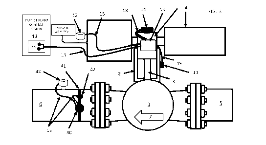
Referring to the drawings, FIG. I. is a schematic illustration of a Shut Down
Valve and a Blow
Down Valve with monitoring system for abnormal situation detection depicting
the
communication as a generic symbol, achieved either over a Wi-Fi network,
Bluetooth
protocol, SMS protocol (a cloud, dedicated application or a handheld device),
or any other
applicable method according to one embodiment of the present invention. SDV's
and/or
BDV's with sensors and the Predictors are able to communicate with different
recipients.
Referring to the drawing FIG, 2, shows the details of at least one SDV J. with
a first detector
system comprising at least one first predictor 20 intended to record if the
SDV's ,flow-
controlling element 2 sticks in closed or open valve position, also including:
- a motion sensor 25 detecting rotational motion of the stem 3 to evaluate
the degree of
friction in said flow-controlling element 2, and/or
- an accelerometer sensor 26 detecting rotational acceleration of the stem 3
to evaluate the
degree of friction in the flow-controlling element 2, and/or
- a shock sensor 27 detecting shock movement and/or ultrasonic vibration
through the stem
3 and
CA 03127477 2021-07-21
WO 2020/153853 6
PCT/N02020/050013
- a first microcontroller 29 controlling sensor data from the sensors 11, 12,
25, 26, 27,
determining stiction of the said flow-controlling element 2, and
- a first wireless interface 30 sending data emitting from said first
microcontroller 29.
The said predictor 20 is fixed on top of the stem 3 and when the actuator 4 is
activated, the
flow- controlling element 2 move between open and closed position.
A second detector system comprising at least one second predictor 40
configurated to record
and estimate leakage of the SDV's flow-controlling element 2 in closed
position, is fixed to at
.. least one downstream inlet pipe 5 and a downstream outlet pipe 6 on the
said SDV 1, also
including
- a temperature sensor 48 detecting temperature in flow fluid, and/or
a second shock sensor 47 detecting shock movement in pipe 6, and/or
- a second vibration sensor 46 detecting ultrasonic vibrations in the flow-
controlling element
2, and/or
- a second microcontroller 49 controlling the sensor data from the sensors 41,
46, 47, 48,
determining flow rate, and
- a second wireless interface 50 sending the data coming from said second
microcontroller
49.
And where the second detector system also including at least one fastener 42
with at least
one strain gauge sensor 41 is damped to the downstream pipe 6 with the said
fastener,
where the pressure in the downstream pipe 6 expands the downstream pipe 6 and
thereby
increases the strain in the fastener 42 and the strain gauge sensor 41, and
the measured
strain that is proportional to the pressure in the downstream pipe 6 and/or at
least one
pressure sensor 43 which may be of piezoceramic type is installed in the
downstream pipe 6
which also measures the pressure in the said downstream piping.
.. Where the said sensors 41 and 43 are wired onto the external sensor
interface 45 which is
controlled by the microcontroller 49 and measured as pipe pressure strain
gauge 43 and pipe
pressure 44, when the said microcontroller 49 wakes up from sleep mode as
described in the
flow chart FIG. 4.
Referring to FIG. 4, which illustrates the program steps for the said
microcontroller 49, where
START 300 is the initial sleep mode state of the microcontroller 49, and the
at least one shock
sensor 47 is installed in the Predictor 40 or at least one piezoelectric
pressure sensor 43 is
detecting sufficient ultrasonic vibrations energy transmitted from the
downstream pipe 6 to
CA 03127477 2021-07-21
WO 2020/153853 7
PCT/N02020/050013
generate an activation signal 310.
Where the microcontroller 49 wake-up 312, and communicate through the wireless
interface
50 with the predictor 20 and receives the valve position data 320 for SDV 1,
and if the flow-
controlling element 2 is open, the program store the data with time 321 and
goes back to
sleep 350, but if the valve position 320 is closed the microcontroller 49 read
and compute
sensor data 325 from at least one of the said sensors 41, 43, 47, and
accelerometer 46 and
temperature sensor 48.
The microcontroller 49 then correlates the measured leak data 325 with a pre-
defined leak
data 326 and if the measured leak data 326 conforms with the pre-defined leak
data 326, a
leak is detected 330 and a leak flow is estimated 331 and a leak alarm 332 is
generated and
stored with real time and SDV 1 specific information in the microcontroller
49, and the
microcontroller 49 can go back to sleep 350.
If the measured leak data 325 does not compare to a predefined leak data 326,
no leak data
is stored and the microcontroller 49 can go back to sleep 350 and wait for the
above
sequence from 312 to sleep 350 to be repeated by either the interrupt of the
shock sensor
310 or wake-up call set by operational procedures to typically between 1 hour
to 24 hours in
the wake up timer 311.
Or where the predictor 20 intended to record if the flow-controlling element 2
sticks in
closed or open valve position or where the said SDV is worn by wear and tear,
where a plant-
control system energizes or de-energizes the hydraulic or pneumatic pressure
in the actuator
4 monitored by the actuator pressure sensor 12 and the movement of the
actuator 4 turns
the stem 3 to open or close the flow-controlling element 2.
The plant-control system while energizing or de-energizing the hydraulic or
pneumatic
pressure in the actuator 4, intermittently closes a normally open contact
valve control 13 and
where at least one strain gauge sensor 11 measures the dynamic force induced
on the flow
controlling element 2 by the rotational torque generated by the actuator 4 and
where the
sensor cable 15 from strain gauge sensor 11 and the sensor cable 16 from
actuator pressure
sensor 12 and the sensor cable 17 from remote valve control 13 may be
connected in
junction box 14 and wired through multi-sensor cable 18 or alternatively
sensor cable 15, 16
and/or 17 be connected to the predictor 20,
External sensor interface 24 which is controlled by the microcontroller 29,
will read the signal
from the strain gauge sensor 11 and detect the stem torque 21 and the signal
from the
actuator pressure sensor 12 to the actuator pressure 22 and the signal from
the remote valve
CA 03127477 2021-07-21
WO 2020/153853 8
PCT/N02020/050013
control 13 to the actuator trigger 23.
And where a change of state in at least one actuator triggers 23 awake the
microcontroller
29 to wake- up from sleep mode which is further described in the flow chart in
FIG 3, which
illustrates the program steps for the said microcontroller 29, where START 200
is in the initial
sleep mode state of the microcontroller 29 and at least one actuator trigger
210 generate an
activation signal where the microcontroller 29 wake up 212 and reads sensor
data 215 from
the sensors 11 and 12, motion sensor 25, accelerometer sensor 26, shock sensor
27 and
temperature sensor 28. And microcontroller 29 transmit said sensor signals
through the
wireless interface 30 through the wireless interface 50 to the microcontroller
49 which then
reads computed sensor data 325 from at least one of the said sensors 41, 43,
47,
accelerometer sensor 46 and temperature sensor 48 and then the microcontroller
49
correlate the measured leak data 325 with a pre-defined leak data 326. If the
measured leak
data 326 conforms with the pre-defined leak data 326 a leak is detected 330
and a leak flow
is estimated 331 and a leak alarm 332 generated and data is stored with real
time. The SDV 1
specific information is stored in the microcontroller 49, and the
microcontroller 49 can go
back to sleep 350.
If the measured leak data 325 does not compare to a pre-defined leak data 326,
no leak data
is stored and the microcontroller 49 can go back to sleep 350 and wait for the
above
sequence from 312 to 350 to be repeated by either the interrupt of the shock
sensor 310 or
wake-up call set by operational procedures to typically between 1 hour to 24
hours in the
wake-up tinier 311 and the microcontroller 29 reads sensor data 215 from at
least one of the
said sensors 11, 12, 25, 26, 27 and 28.
The microcontroller 29 then compute the measured stiction data 216 and compare
with the
pre-defined acceptable stiction data 220 which define the conditions for
acceptable stiction
in SDV 1 and therefore if correlation of stiction data 221 is outside
acceptable limits, stiction
deviation data 222 is stored and a stiction alarm 223 is generated and stored
with real time
SCAI I specific information in the microcontroller 29.
If the measured stiction data 216 does not compare to a pre-defined stiction
data set 220 no
stiction deviation is detected and the microcontroller 29 compute the measured
movement
data set 217 and compare with the pre-defined acceptable movement data 230
which
defines the conditions for acceptable movement of the flow-controlling element
2 and
therefore if correlation of movement data 231 is out of acceptable limits due
to wear and
tear or other actuator problems, movement deviation data 231 is stored and a
movement
alarm 223 is generated and stored with real time and SDV 1 specific
information in the
CA 03127477 2021-07-21
WO 2020/153853 9
PCT/N02020/050013
microcontroller 29.
the measured movement data 217 does not compare to a pre-defined movement data
230
no movement deviation is detected and the inicrocontroller 29 goes back to
sleep 350 and
wait for the above sequence from wake-up timer 212 to sleep-mode 250 to be
repeated by
either the interrupt of the actuator trigger 210 or wake-up call set by
operational procedures,
typically between 1 hour to 2.4 hours in the wake-up timer 211.