Note: Descriptions are shown in the official language in which they were submitted.
1
CA 03127992 2021-07-27
WO 2020/162555 PCT/JP2020/004627
Description
Title of Invention: GUIDE MEMBER
Technical Field
[0001] The present invention relates to a guide member that is attachable
to a filling valve of
a filler device that includes: the filling valve for filling a container with
a product; and
a container supporting unit configured to be lifted and lowered relative to
the filling
valve, the filling valve being provided with a filling port configured to be
opened upon
the container mounted on the container supporting unit being lifted as a
result of the
container supporting unit being lifted, and to be closed upon the container
mounted on
the container supporting unit being lowered as a result of the container
supporting unit
being lowered.
Background Art
[0002] A factory for manufacturing a product such as beverages is provided
with a filler
device that injects a beverage into a container such as a bottle or a can. The
filler
device is provided with, for example: a filler bowl in which a beverage is
stored before
being filled into a container; a plurality of filling valves that are provided
in the filler
bowl; container supporting units that are respectively provided below the
filling valves
and move along a circumferential trajectory in synchronization with the
rotation of the
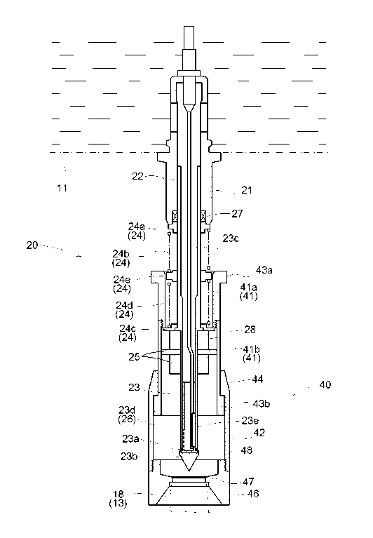
filler bowl; a carry-in conveyer that conveys containers to the container
supporting
units; and a carry-out conveyer that conveys containers from the container
supporting
units (see FIGS. 1 and 2).
[0003] Containers that have been conveyed from the carry-in conveyer to the
container
supporting units are filled with a predetermined amount of beverage using the
filling
valves until the containers are conveyed from the container supporting units
to the
carry-out conveyor.
[0004] Each filling valve includes, for example: a housing that is tubular
and penetrates
through the bottom surface of the filler bowl; an outer valve body that is
tubular and is
inserted into the housing; an inner valve body that is tubular, the upper end
thereof
being fixed to the housing, and is inserted into the outer valve body; and a
biasing unit
that biases the outer valve body downward relative to the housing.
[0005] The container supporting units are configured to be lifted and
lowered relative to the
filling valves. Upon the opening portion of a container mounted on a container
supporting unit pressing a press-target portion provided on the outer valve
body of a
filling valve upward as a result of the container supporting unit being
lifted, the outer
valve body is moved upward resisting a biasing force applied by the biasing
portion,
and accordingly a filling port that is provided at the lower end of the inner
valve body
2
CA 03127992 2021-07-27
WO 2020/162555 PCT/JP2020/004627
is opened, i.e., the filling valve is opened. The product stored in the filler
bowl passes
through the respective internal spaces of the outer valve body and the inner
valve body,
and is filled into a container via the filling port.
[0006] The filling valve is configured such that: the filling of the
container with the product
is stopped upon the internal pressure of the container becoming equal to the
internal
pressure of the filler bowl; the outer valve body is moved downward as a
result of the
container supporting unit being lowered; and accordingly the filling port is
closed by
the lower end of the outer valve body, i.e., the filling valve is closed.
[0007] As described above, each filling valve is configured to be opened
and closed as a
result of a container being lifted and lowered. Therefore, if a container is
not mounted
at an appropriate position on a container supporting unit, there is the risk
of the outer
valve body not being properly lifted by the container, the filling port not
being opened
wide enough, and the flow rate of the beverage not reaching a predetermined
rate. For
example, if the flow rate of the beverage is lower than a predetermined rate,
the time
required to fill a container with a predetermined amount of beverage
increases.
Therefore, there is demand for a mechanism that can guide the opening portions
of
containers to appropriate positions relative to the filling ports.
[0008] Note that no appropriate prior art document that discloses the above-
described filler
device, which is prior art of the present invention, has been found, and
therefore no
prior art document such as a patent document is indicated herein.
Summary of Invention
[0009] The present invention has been made in view of the above-described
situation, and an
objective thereof is to provide a guide member that is attachable to a filling
valve, and
is capable of appropriately adjusting the respective positions of a container
mounted on
a container supporting unit and a filling port.
[0010] Characteristic configurations of a guide member according to the
present invention
for achieving the above-described objective lie in that the guide member is a
guide
member that is attachable to a filling valve of a filler device that includes:
the filling
valve for filling a container with a product; and a container supporting unit
configured
to be lifted and lowered relative to the filling valve, the filling valve
being provided
with a filling port configured to be opened upon the container mounted on the
container supporting unit being lifted as a result of the container supporting
unit being
lifted, and to be closed upon the container mounted on the container
supporting unit
being lowered as a result of the container supporting unit being lowered, the
guide
member including: an upper main body that is positioned so as to enclose the
filling
valve and so as to be movable in a vertical direction relative to the filling
port; and a
lower main body that is positioned so as to enclose the upper main body and is
3
CA 03127992 2021-07-27
WO 2020/162555 PCT/JP2020/004627
configured to be slidable on the surface of the upper main body, wherein the
lower
main body is provided with an abutting portion that protrudes inward relative
to the
inner surface of the lower main body and that is configured to abut against at
least an
opening portion of the container mounted on the container supporting unit, and
the
guide member is configured to allow the container to be lifted while keeping
the
abutting portion abutted against the opening portion, thereby guiding the
opening
portion to an appropriate position relative to the filling port.
[0011] With the above-described configuration, the guide member guides the
opening
portion of the container to an appropriate position relative to the filling
port of the
filling valve. Thus, it is possible to appropriately open the filling port
upon the
container being moved upward. Upon the filling port being opened, the product
supplied from the filler bowl to the respective internal spaces of the outer
valve body
and the inner valve body is appropriately filled into the container via the
filling port.
Note that the filling of the container with the product is stopped upon the
internal
pressure of the container becoming equal to the internal pressure of the
filler bowl.
[0012] Also, the upper main body and the lower main body of the guide
member are
configured to be telescopic, and thus the guide member can expand and contract
in a
vertical direction. Therefore, before a container abuts against the guide
member, the
guide member is in an expanding state, and the opening portion of the
container can be
swiftly abutted against the abutting portion. Therefore, the guide member can
thereafter smoothly guide the opening portion. Also, when the filling valve
fills the
container with the product, the guide member is in a contracted state.
Therefore,
although the guide member is positioned so as to enclose the filling valve,
the guide
member is not an obstruction in terms of space.
[0013] In the present invention, it is preferable that a lower outward
protruding portion that
protrudes outward is provided at a lower end of the upper main body, an inward
protruding portion that protrudes inward is provided at an upper end of the
lower main
body, the upper main body and the lower main body are configured to be
slidable on
each other along a common axis such that at least the lower outward protruding
portion
slides on the inner surface of the lower main body, or the inward protruding
portion
slides on the outer surface of the upper main body, and the lower main body is
configured such that the inward protruding portion and the lower outward
protruding
portion hook on each other due to the weight of the lower main body.
[0014] With the above-described configuration, the inward protruding
portion and the lower
outward protruding portion hook on each other due to the weight of the lower
main
body, and thus the lower main body is suspended from the upper main body.
[0015] In the present invention, it is preferable that the lower main body
is provided with a
push-up portion that is configured to come into contact with the lower outward
4
CA 03127992 2021-07-27
WO 2020/162555 PCT/JP2020/004627
protruding portion, and the push-up portion is configured to, when in contact
with the
lower outward protruding portion, push up the upper main body as a result of
the lower
main body moving upward due to the container being lifted.
[0016] With the above-described configuration, upon the lower main body
being moved
upward, the push-up portion comes into contact with the lower outward
protruding
portion and pushes up the upper main body. Therefore, it is unnecessary to
provide a
dedicated power source for moving the upper main body.
[0017] In the present invention, it is preferable that an upper outward
protruding portion that
protrudes outward is provided at an upper end of the upper main body, and the
upper
main body is configured such that the inward protruding portion and the upper
outward
protruding portion hook on each other when the lower main body is pushed up.
[0018] With the above-described configuration, when the lower main body and
the upper
main body need to be pushed up, the upper main body is pushed up when the
lower
main body is pushed up. Therefore, it is unnecessary to separately push up the
lower
main body and the upper main body.
[0019] In the present invention, it is preferable that the upper main body
and the lower main
body are tubular, and a side surface of the lower main body is provided with
an
opening portion.
[0020] With the above-described configuration, it is possible to look
inside the lower main
body through the opening portion. Therefore, when the abutting portion fails
to abut
against the opening portion, it is easy to find the failure.
[0021] In the present invention, it is preferable that the abutting portion
is provided on an
abutting member that is detachably attached to the lower main body.
[0022] With the above-described configuration, the abutting member can be
replaced with
another member that fits the shape of the container, for example. Also, when a
failure
occurs in the abutting member, it is possible to replace only the abutting
member. Fur-
thermore, it is possible to form the upper main body and the lower main body
from a
metal material, and form the abutting member from a resin material. Therefore,
it is
possible to mitigate the impact of the abutting portion of the abutting member
when
abutting against the opening portion.
[0023] In the present invention, it is preferable that the filling valve
includes: a housing that
is tubular and penetrates through the bottom surface of a filler bowl for
storing the
product; an outer valve body that is tubular and is inserted into the housing;
an inner
valve body that is tubular, the upper end thereof being fixed to the housing,
and is
inserted into the outer valve body; and a biasing unit that biases the outer
valve body
downward relative to the housing, the outer valve body is provided with a
press-target
portion that is configured to be pressed upward by the opening portion, the
filling
valve is configured such that the opening portion of the container mounted on
the
5
CA 03127992 2021-07-27
WO 2020/162555 PCT/JP2020/004627
container supporting unit presses the press-target portion and moves the outer
valve
body upward as a result of the container supporting unit being lifted, and
accordingly
the filling port provided in a lower end of the inner valve body is opened,
and the outer
valve body is moved downward as a result of the container supporting unit
being
lowered, and accordingly the filling port is closed by a lower end of the
outer valve
body, the biasing unit includes compression coil springs provided between the
housing
and the press-target portion, the compression coil springs include an upper
spring
whose upper end is fixed to an upper fixing portion provided on the housing
side; and
a lower spring whose lower end is fixed to a lower fixing portion provided on
the
press-target portion side, the lower end of the upper spring and the upper end
of the
lower spring are coupled to each other by a coupling portion that is provided
so as to
be slidable on the surface of the outer valve body, the upper main body
includes an
upper case and a lower case that is detachably attached to the upper case, the
upper
case is located above the lower fixing portion, and is configured to be
restricted from
moving downward upon the lower end of the upper case coming into contact with
the
lower fixing portion, and the lower case is configured to extend downward
relative to
the lower fixing portion, and is configured to allow the press-target portion
to slide on
the inner surface of the lower case.
[0024] In the filling valve with the above-described configuration, the
compression coil
springs, which constitute a biasing unit, include an upper spring and a lower
spring.
Therefore, coil springs that are shorter than the stroke of the valve for
opening the
filling port can be employed as the upper spring and the lower spring.
[0025] The likelihood of a coil spring meandering is proportional to the
length of the coil
spring. If a coil spring meanders a lot when compressed, there is the risk of
the coil
spring coming into contact with the inner surface of the guide member and
causing a
failure when the filling port is to be opened. As in the above-described
configuration,
by using a plurality of coil springs that are short, considering the length of
the stroke,
and coupling them to each other in series using the coupling portion, it is
possible to
reduce the degree of meandering, compared to when using one long coil spring.
Thus,
it is possible to prevent a coil spring from coming into contact with the
inner surface of
the guide member. The guide member can be favorably attached to the filling
valve
with such a configuration. The guide member is configured as described above.
Therefore, the guide member attached to the filling valve does not cause a
failure when
the filling port is to be opened. Note that the upper main body is provided
such that the
upper case is suspended from the lower fixing portion due to the weight of the
upper
main body.
[0026] In the present invention, it is preferable that the respective outer
diameters of the
upper fixing portion, the lower fixing portion, and the coupling portion of
the filling
6
CA 03127992 2021-07-27
WO 2020/162555 PCT/JP2020/004627
valve are larger than the diameter of the upper spring and the lower spring,
the inner
diameter of the upper case is larger than the respective outer diameters of
the upper
fixing portion, the lower fixing portion, and the coupling portion, and the
upper case is
configured to be slidable at least on the coupling portion, the inner diameter
of the
lower case is larger than the outer diameter of the press-target portion, and
the lower
case is configured to be slidable at least on the press-target portion, and
the length of
the upper case is such that, when the lower end of the upper case covers at
least a
portion of the lower fixing portion, the upper end of the upper case covers
the coupling
portion, but does not cover the housing, whereas when the upper end of the
upper case
covers at least a portion of the housing, the lower end of the upper case
covers the
coupling portion, but does not cover the lower fixing portion.
[0027] With the above-described configuration, the upper case of the guide
member is
always slidable on the coupling portion, and can be lowered to a position
where the
upper case covers the lower fixing portion, or lifted to a position where the
upper case
covers the upper fixing portion, while being kept in such a state. During such
movement, the lower case of the guide member slides on the press-target
portion. The
guide member slides while being guided by the coupling portion that slides on
the
outer valve body and the press-target portion that is provided on the outer
valve body.
Therefore, it is ensured that the guide member moves in a vertical direction
along the
axis of the outer valve body, i.e., the axis of the filling valve.
Brief Description of Drawings
[0028] [fig.11FIG. 1 is a plan view schematically showing a filler device.
[fig.21FIG. 2 is a cross-sectional view showing a main part of the filler
device.
[fig.31FIG. 3 illustrates injection of whisky performed using the filler
device.
[fig.41FIG. 4 illustrates details of a guide member according to the present
invention.
[fig.51FIG. 5 illustrates details of the guide member according to the present
invention.
[fig.61FIG. 6 illustrates an opening portion provided in the guide member.
Description of Embodiments
[0029] The following describes a preferred embodiment of a guide member
according to the
present invention with reference to the drawings. Note that the following
embodiment
describes an example in which a filler device is provided in a factory for
manu-
facturing whisky, which is a commercial product, and containers that are to be
filled
with whisky using filling valves are bottles. The term "whisky" in the present
speci-
fication is not intended to limit its main ingredient to a specific ingredient
among malt,
corn, rye, etc., or exclude a specific ingredient from them, or limit its
production
region to a specific region among the United States, Canada, Japan, etc., or
exclude a
specific area from them. In the drawings, solid arrows indicate the flow of
whisky, and
7
CA 03127992 2021-07-27
WO 2020/162555 PCT/JP2020/004627
dotted arrows indicate the flow of air.
[0030] As shown in FIGS. 1 and 2, a filler device 10 includes, for example:
a filler bowl 11
in which whisky is stored; a plurality of filling valves 20 provided in the
filler bowl 11;
container supporting units 12 that are respectively provided below the filling
valves 20
and move along a circumferential trajectory in synchronization with the
rotation of the
filler bowl 11; a carry-in conveyer 14 that conveys bottles 13 to the
container
supporting units 12; and a carry-out conveyer 15 that conveys bottles 13 from
the
container supporting units 12.
[0031] The filler bowl 11 is a tank for storing whisky that is to be
injected into the bottles
13. A plurality of (e.g., eighteen) filling valves 20 are arranged on the
filler bowl 11 at
equal intervals along a circumferential trajectory. The filler bowl 11 and the
filling
valves 20 are corrosion resistant to the product that is handled, i.e.,
whisky, and are
also formed using a durable material such as stainless steel, which is a
typical example.
[0032] The bottles 13, which have been conveyed from the carry-in conveyer
14 to the
container supporting units 12, are filled with a predetermined amount of
whisky using
the filling valves 20 until the bottles 13 are conveyed from the container
supporting
units 12 by the carry-out conveyer 15. The bottles 13 that have been filled
with whisky
are conveyed from the container supporting units 12 to the carry-out conveyer
15, and
then a cap is put on each of the bottles 13.
[0033] The carry-in conveyer 14 and the carry-out conveyer 15 are formed
using a conveyor
mechanism that is a well-known mechanism such as a belt mechanism or a screw
mechanism. A carry-in star wheel 16 and a carry-out star wheel 17 are provided
to
transfer the bottles 13 between the container supporting units 12 and the
carry-in
conveyer 14, and between the container supporting units 12 and the carry-out
conveyer
15.
[0034] The container supporting units 12 are formed as mounts on which the
bottles 13 can
be respectively mounted. The container supporting units 12 are configured to
be lifted
and lowered by a cam mechanism (not shown) according to predetermined timing
while moving along the rotation trajectory in synchronization with the
rotation of the
filler bowl 11.
[0035] The following describes the filling valves 20. As shown in FIGS. 4
and FIG. 5 in
detail, each filling valve 20 includes, for example: a housing 21 that is
tubular and
penetrates through the bottom surface of the filler bowl 11; an outer valve
body 22 that
is tubular and is inserted into the housing 21; an inner valve body 23 that is
tubular, the
upper end thereof being fixed to the housing 21, and is inserted into the
outer valve
body 22; and a biasing unit 24 that biases the outer valve body 22 downward
relative to
the housing 21.
[0036] The outer valve body 22 is provided with a press-target portion 25
that is configured
8
CA 03127992 2021-07-27
WO 2020/162555 PCT/JP2020/004627
to be pressed upward by an opening portion 18 of a bottle 13.
[0037] A seal 27 is provided on a surface of the housing 21 on which the
outer valve body
22 slides. The seal 27 is formed using a well-known material such as rubber,
resin, or
elastomer.
[0038] The biasing unit 24 includes compression coil springs provided
between the housing
21 and the press-target portion 25. The compression coil springs include: an
upper
spring 24b whose upper end is fixed to an upper fixing portion 24a provided on
the
housing 21 side; and a lower spring 24d whose lower end is fixed to a lower
fixing
portion 24c provided on the press-target portion 25 side. The compression coil
springs
are manufactured from a well-known material such as a steel wire, a piano
wire, or a
stainless steel wire, and are subjected to well-known end processing so as to
form a
closed end or an open end, for example.
[0039] The diameter of the upper spring 24b and the lower spring 24d is
smaller than the
inner diameter of a guide member 40 described below, and is larger than the
outer
diameter of the outer valve body 22, and is also set to an appropriate size so
that the
springs, when expanding and contracting, do not come into contact with the
inner
surface of the guide member 40 or the outer surface of the outer valve body
22. Fur-
thermore, the length of the upper spring 24b and the lower spring 24d is set
to an ap-
propriate length so that the springs do not meander when expanding and
contracting.
Preferably, the upper spring 24b and the lower spring 24d are wound in
directions
different from each other.
[0040] The lower end of the upper spring 24b and the upper end of the lower
spring 24d are
coupled to each other by a coupling portion 24e that is provided so as to be
slidable on
the surface of the outer valve body 22.
[0041] In the present embodiment, the upper fixing portion 24a, the lower
fixing portion
24c, and the coupling portion 24e are formed using a polyacetal resin, for
example.
[0042] Both ends of the upper spring 24b and both ends of the lower spring
24d are each
provided with a so-called end turn portion including one to several end turns
that do
not to contribute to expansion or contraction. The upper spring 24b and the
lower
spring 24d are located at predetermined positions such that the end turn
portions
thereof are fitted to the upper fixing portion 24a, the lower fixing portion
24c, and the
coupling portion 24e, respectively.
[0043] With the above-described configuration, the press-target portion 25
is biased
downward relative to the housing 21, due to an elastic force applied by the
biasing unit
24.
[0044] Note that the respective outer diameters of the upper fixing portion
24a, the lower
fixing portion 24c, and the coupling portion 24e of the filling valves 20 are
larger than
the diameter of the upper spring 24b and the lower spring 24d.
9
CA 03127992 2021-07-27
WO 2020/162555 PCT/JP2020/004627
[0045] As shown in FIG. 5, as a result of the bottle 13 being lifted due to
the container
supporting unit 12 being lifted, the opening portion 18 of the bottle 13
mounted on the
container supporting unit 12 presses the press-target portion 25 provided on
the outer
valve body 22 upward. Consequently, the outer valve body 22 is moved upward
resisting the biasing force applied by the biasing unit 24, and accordingly a
filling port
26 that is provided at the lower end of the inner valve body 23 is opened.
Then, whisky
in the filler bowl 11 passes through the respective internal spaces of the
housing 21, the
outer valve body 22, and the inner valve body 23, and is filled into the
bottle 13 via the
filling port 26.
[0046] Note that the inner valve body 23 includes: a valve body 23b that is
provided with a
seal 23a that seals the gap between the inner valve body 23 and the outer
valve body
22 so as to be liquid-tight; and a pipe body 23c whose lower end is fixed to
the valve
body 23b and whose upper end is fixed to the housing 21. Note that the seal
23a is
made of a well-known material such as rubber, resin, or elastomer.
[0047] An opening 23d is provided in the valve body 23b. This opening 23d
constitutes the
filling port 26. Note that the opening 23d is provided with a mesh member. The
mesh
member functions as a filter that prevents a foreign substance other than
whisky, if
present in the whisky in the filler bowl 11, from being filled into the bottle
13.
[0048] Also, an opening 23e that is opened upon the opening 23d being
opened is provided
in the lower end of the pipe body 23c. The opening 23e functions as an air
vent for dis-
charging the air in the bottle 13 to the outside when the bottle 13 is filled
with whisky.
[0049] The filling valve 20 is configured such that: the filling of the
bottle 13 with whisky is
stopped upon the internal pressure of the bottle 13 becoming equal to the
internal
pressure of the filler bowl 11; the outer valve body 22 is moved downward as a
result
of the container supporting unit 12 being lowered; and accordingly the filling
port 26 is
closed by the lower end of the outer valve body 22.
[0050] The guide member 40 according to the present invention is configured
to be de-
tachably attached to such a filling valve 20.
[0051] As shown in FIGS. 4 to 6, the guide member 40 includes: an upper
main body 41 that
is positioned so as to enclose the outer valve body 22 and so as to be movable
in a
vertical direction relative to the outer valve body 22; and a lower main body
42 that is
positioned so as to enclose the upper main body 41 and is configured to be
slidable on
the surface of the upper main body 41. The upper main body 41 and the lower
main
body 42 are tubular members, and are made of metal such as stainless steel in
the
present embodiment. An opening portion 45 is provided in a side surface of the
lower
main body 42 (see FIG. 6).
[0052] The upper main body 41 includes an upper case 41a and a lower case
41b. The upper
case 41a and the lower case 41b are detachably coupled to each other by female
screws
10
CA 03127992 2021-07-27
WO 2020/162555 PCT/JP2020/004627
and male screws engaging with each other. However, a configuration that
enables the
upper case 41a and the lower case 41b to be detachable is not limited in such
a way.
The upper case 41a and the lower case 41b may be configured such that, once
they are
coupled to each other, they cannot be disassembled.
[0053] An upper outward protruding portion 43a that protrudes outward is
provided at the
upper end of the upper main body 41, i.e., the upper end of the upper case
41a. Fur-
thermore, a lower outward protruding portion 43b that protrudes outward is
provided at
the lower end of the upper main body 41, i.e., the lower end of the lower case
41b. An
inward protruding portion 44 that protrudes inward is provided at the upper
end of the
lower main body 42.
[0054] The lower surface of the inward protruding portion 44 and the upper
surface of the
lower outward protruding portion 43b hook on each other due to the weight of
the
lower main body 42, and thus the lower main body 42 is suspended from the
upper
main body 41.
[0055] The upper main body 41 and the lower main body 42 are configured to
be slidable on
each other along a common axis such that the inward protruding portion 44
slides on
the outer surface of the upper main body 41.
[0056] An abutting member 46 that includes an abutting portion 47 that
protrudes inward
relative to the inner surface of the lower main body 42 and that can abut
against at least
the opening portion 18 of the bottle 13 mounted on the container supporting
unit 12 is
detachably attached to the lower main body 42. The abutting member 46 is made
of a
polyacetal resin, for example. The abutting member 46 is configured to be
detachably
attachable to the lower main body 42 by being screwed into the lower main body
42.
However, note that the abutting member 46 may be provided integrally with the
lower
main body 42.
[0057] Furthermore, the abutting member 46 is provided with a push-up
portion 48 that is
configured to come into contact with the lower outward protruding portion 43b.
The
push-up portion 48 is configured to push up the upper main body 41 as a result
of the
lower main body 42 moving upward due to the bottle 13 being lifted when the
upper
surface of the push-up portion 48 is in contact with the lower surface of the
lower
outward protruding portion 43b. Note that the push-up portion 48 may be
provided in-
tegrally with the inner surface of the lower main body 42.
[0058] The upper case 41a of the upper main body 41 is located above the
lower fixing
portion 24c, and is configured to be restricted from moving downward upon the
lower
end of the upper case 41a coming into contact with the lower fixing portion
24c.
[0059] The inner diameter of the upper case 41a is larger than the
respective outer diameters
of the upper fixing portion 24a, the lower fixing portion 24c, and the
coupling portion
24e, and the upper case 41a is configured to be slidable at least on the
coupling portion
11
CA 03127992 2021-07-27
WO 2020/162555 PCT/JP2020/004627
24e.
[0060] The lower case 41b is configured to extend downward relative to the
lower fixing
portion 24c, and is configured to allow the press-target portion 25 to slide
on the inner
surface of the lower case 41b.
[0061] The inner diameter of the lower case 41b is larger than the outer
diameter of the
press-target portion 25, and the lower case 41b is configured to be slidable
at least on
the press-target portion 25.
[0062] The length of the upper case 41a is such that, when the lower end of
the upper case
41a covers at least a portion of the lower fixing portion 24c as shown in FIG.
4, the
upper end of the upper case 41a can cover the coupling portion 24e, but cannot
cover
the housing 21, whereas when the upper end of the upper case 41a covers at
least a
portion of the housing 21 as shown in FIG. 5, the lower end of the upper case
41a can
cover the coupling portion 24e, but cannot cover the lower fixing portion 24c.
[0063] The guide member 40 with the above-described configuration allows
the bottle 13 to
be lifted while keeping the abutting portion 47 of the abutting member 46
abutted
against the opening portion 18, thereby guiding the opening portion 18 to an
ap-
propriate position relative to the filling port 26. The following describes
such a
situation with reference to FIG. 3.
[0064] FIG. 3 shows filling valves 20a to 20e that are located at
appropriate positions in the
filler device 10, container supporting units 12a to 12e corresponding to
thereto, bottles
13a to 13e that are respectively mounted on the container supporting units 12a
to 12e,
and guide members 40a to 40e that are attached to the filling valves 20a to
20e. Note
that the suffixes "a" to "e" added to the reference numerals of components are
provided only for the purpose of facilitating description, and the
configurations of the
components are the same.
[0065] In FIG. 3, the first one from the left shows a state immediately
after the bottle 13a
has been conveyed from the carry-in conveyer 14 to the container supporting
unit 12a,
for example. At this time, the container supporting unit 12a has not been
lifted, and
therefore the opening portion 18a of the bottle 13a is not abutted against the
abutting
member 46a of the guide member 40a.
[0066] In FIG. 3, the second one from the left shows a state after a
certain period of time has
elapsed from when the lifting of the container supporting unit 12b was
started, the
opening portion 18b of the bottle 13b is abutted against the abutting member
46b of the
guide member 40b, and lifting of the lower main body 42b has started. At this
time, the
filling of the bottle 13b with whisky has not been started.
[0067] In FIG. 3, the third one from the left shows a state in which the
filling port 26 is open
due to the opening portion 18c of the bottle 13c, which abuts against the
abutting
member 46c, lifting the lower main body 42c and the upper main body 41c of the
12
CA 03127992 2021-07-27
WO 2020/162555 PCT/JP2020/004627
guide member 40c, and further pressing the press-target portion 25, as a
result of the
container supporting unit 12c being further lifted. At this time, whisky in
the filler
bowl 11 passes through the respective internal spaces of the housing 21, the
outer
valve body 22, and the inner valve body 23, and is filled into the bottle 13c
via the
filling port 26.
[0068] In FIG. 3, the fourth one from the left shows a state after the
bottle 13d has been
filled with whisky, the press-target portion 25 has been released from the
pressure
applied by the opening portion 18d of the bottle 13d as a result of the
container
supporting unit 12d being lowered, and the filling port 26 is closed. Although
the
opening portion 18d of the bottle 13d that abuts against the abutting member
46d is
still lifting up the lower main body 42d of the guide member 40d, the upper
main body
41 has been lowered to the initial suspension position.
[0069] In FIG. 3, the fifth one from the left shows a state immediately
before the bottle 13e
is conveyed from the container supporting unit 12e to the carry-out conveyer
15, for
example. At this time, the container supporting unit 12e has been sufficiently
lowered,
and therefore the opening portion 18e of the bottle 13e does not abut against
the
abutting member 46e of the guide member 40e.
[0070] Although the product in the above-described embodiment is whisky,
which is a
beverage, the product is not limited to whisky. The product may be any product
that is
to be filled into containers such as bottles, cans, PET bottles, or paper
cartons, and
examples of the product include alcoholic beverages such as rum, tequila, gin,
brandy,
and wine, beverages such as water, coffee, and milk, seasonings, cosmetics,
and drugs.
[0071] Note that each filling valve 20 is configured such that the height
position of the
press-target portion 25 can be adjusted by chanting the number, the thickness,
and so
on, of spacers 28 according to the shape of the containers.
[0072] The upper outward protruding portion 43a that protrudes outward is
provided at the
upper end of the upper main body 41, i.e., the upper end of the upper case
41a.
[0073] If the abutting member 46 is removed from the lower main body 42 and
the lower
main body 42 is pushed up, the upper surface of the inward protruding portion
44 of
the lower main body 42 and the lower surface of the upper outward protruding
portion
43a of the upper main body 41 abut against each other, and thus the upper main
body
41 is also pushed up.
[0074] Both the lower main body 42 and the upper main body 41 are pushed up
until the
press-target portion 25 and the spacers 28 are seen. In this state, the
number, the
thickness, and so on, of the spacers 28 can be easily changed. The height
position of
the press-target portion 25 can be easily adjusted by making changes to the
spacers 28.
[0075] Note that the upper main body 41 and the lower main body 42 are
configured such
that, in a state where the push-up portion 48 of the abutting member 46 and
the lower
13
CA 03127992 2021-07-27
WO 2020/162555 PCT/JP2020/004627
outward protruding portion 43b of the upper main body 41 are in contact with
each
other, the upper surface of the inward protruding portion 44 of the lower main
body 42
and the lower surface of the upper outward protruding portion 43a of the upper
main
body 41 do not abut against each other, and even in a state where the abutting
member
46 is removed and the upper surface of the inward protruding portion 44 of the
lower
main body 42 and the lower surface of the upper outward protruding portion 43a
of the
upper main body 41 abut against each other, the lower end of the lower main
body 42
covers the lower outward protruding portion 43b of the upper main body 41.
[0076] If it is unnecessary to change the height position of the press-
target portion 25, the
filling valves 20 may not be provided with the upper outward protruding
portion 43a.
[0077] The above-described embodiment is an example of the present
invention, and is not
intended to limit the present invention. The specific configuration of each
portion may
be subjected to design changes as appropriate, as long as operative effects
can be
achieved.
Reference Signs List
[0078] 10: Filler Device
11: Filler Bowl
12: Container Supporting Unit
13: Bottle (Container)
18: Opening Portion
20: Filling Valve
21: Housing
22: Outer Valve Body
23: Inner Valve Body
23a: Seal
23b: Valve Body
23c: Pipe Body
23d: Opening
23e: Opening
24: Biasing Unit
24a: Upper Fixing Portion
24b: Upper Spring
24c: Lower Fixing Portion
24d: Lower Spring
24e: Coupling Portion
25: Press-target Portion
26: Filling Port
14
CA 03127992 2021-07-27
WO 2020/162555
PCT/JP2020/004627
27: Seal
28: Spacer
40: Guide Member
41: Upper Main Body
41a: Upper Case
41b: Lower Case
42: Lower Main Body
43a: Upper Outward Protruding Portion
43b: Lower Outward Protruding Portion
44: Inward Protruding Portion
45: Opening Portion
46: Abutting Member
47: Abutting Portion
48: Push-up Portion