Note: Descriptions are shown in the official language in which they were submitted.
CA 03128030 2021-07-27
WO 2020/160218
PCT/US2020/015810
SUTURE MANAGEMENT DEVICE AND METHODS
CROSS-REFERENCES TO RELATED APPLICATIONS
[0001] This application claims the benefit of U.S. Provisional Application
Serial Number
62/799,574 filed on January 31, 2019, and entitled "SUTURE MANAGEMENT DEVICE
AND METHODS", the entirety of which is hereby incorporated by reference
herein.
[0002] This application is generally related to U.S. Provisional Application
Serial Number
62/541,375 filed on August 4, 2017, entitled "DELIVERY SYSTEM AND METHODS FOR
RESHAPING A HEART VALVE ANNULUS, INCLUDING THE USE OF MAGNETIC
TOOLS", and U.S. Non-Provisional Application Serial Number 16/056,220 filed on
August
6,2018, entitled "DELIVERY SYSTEM AND METHODS FOR RESHAPING A HEART
VALVE ANNULUS, INCLUDING THE USE OF MAGNETIC TOOLS", which are
incorporated by reference herein for all purposes.
FIELD OF THE INVENTION
[0003] The invention is directed to devices, systems, and methods for managing
an
elongate element having sections with differing mechanical properties, in
particular, a suture-
wire element to facilitate deployment of a heart implant having a bridging
element.
BACKGROUND OF THE INVENTION
[0004] Treatments for mitral valve regurgitation are widely varied. A
particularly
promising approach entails delivery of an implant having a bridging element
across a
.. chamber of the heart such that tensioning of the implant reshapes the heart
chamber, thereby
improving coaptation of the mitral valve. Some such implants are delivered
intravascularly
by advancing a suture-wire element, a portion of which includes a bridging
element, through
the vasculature of the patient from a first vascular access point and exiting
through a second
vascular access point. While this delivery technique has marked advantages
over
conventional approaches, it involves use of a relatively long suture-wire
element. Managing
this element before and during advancement through the vasculature can be
cumbersome,
particularly since the element must be maintained as sterile and smoothly fed
into the
vasculature without tangling. Typically, the element is a suture-wire having
sections of
differing materials, for example, a wire section of a stiff material having
compressive
.. strength (e.g. guidewire, needle) and a suture section having reduced
compressive strength
1
CA 03128030 2021-07-27
WO 2020/160218
PCT/US2020/015810
prone to tangling and catching adjacent objects. Further, having each end of
the continuous
suture wire element stored side by side in small lumen of long catheter to be
deployed one
sequentially before the other presents other unique challenges. The different
mechanical
properties of these differing sections and the preferred deployment scheme
present unique
challenges that are unmet by conventional suture or guidewire management
approaches.
Therefore, there is a need for devices and methods that provide improved
storage and
management of suture-wire elements for deploying an implant. It is desirable
for such
devices and methods to also maintain sterility of the element and facilitate
smooth dispensing
when needed.
I. The Anatomy of a Healthy Heart
[0005] As can be seen in FIG. 2A, the human heart is a double-sided (left and
right side),
self-adjusting pump, the parts of which work in unison to propel blood to all
parts of the
body. The right side of the heart receives poorly oxygenated ("venous") blood
from the body
from the superior vena cava and inferior vena cava and pumps through the
pulmonary artery
to the lungs for oxygenation. The left side receives well-oxygenation
("arterial") blood from
the lungs through the pulmonary veins and pumps into the aorta for
distribution to the body.
[0006] The heart has four chambers, two on each side ¨ the right and left
atria, and the right
and left ventricles. The atriums are the blood-receiving chambers, which pump
blood into the
ventricles. The ventricles are the blood-discharging chambers. A wall composed
of fibrous
and muscular parts, called the interatrial septum separates the right and left
atriums (see
FIGS. 2B-2D). An anatomic landmark on the interatrial septum is an oval,
thumbprint sized
depression called the oval fossa, or fossa ovalis (FO), shown in FIG. 2C,
which is a remnant
of the oval foramen and its valve in the fetus and thus is free of any vital
structures such as
valve structure, blood vessels and conduction pathways. The synchronous
pumping actions of
the left and right sides of the heart constitute the cardiac cycle. The cycle
begins with a
period of ventricular relaxation, called ventricular diastole. The cycle ends
with a period of
ventricular contraction, called ventricular systole 3. The heart has four
valves (see FIGS. 2B
and 2C) that ensure that blood does not flow in the wrong direction during the
cardiac cycle;
that is, to ensure that the blood does not back flow from the ventricles into
the corresponding
atria, or back flow from the arteries into the corresponding ventricles. The
valve between the
left atrium and the left ventricle is the mitral valve. The valve between the
right atrium and
2
CA 03128030 2021-07-27
WO 2020/160218
PCT/US2020/015810
the right ventricle is the tricuspid valve. The pulmonary valve is at the
opening of the
pulmonary artery. The aortic valve is at the opening of the aorta.
[0007] At the beginning of ventricular diastole (i.e., ventricular filling),
the aortic and
pulmonary valves are closed to prevent back flow from the arteries into the
ventricles.
Shortly thereafter, the tricuspid and mitral valves open, as shown in FIG. 2B,
to allow flow
from the atriums into the corresponding ventricles. Shortly after ventricular
systole (i.e.,
ventricular emptying) begins, the tricuspid and mitral valves close, as shown
in FIG. 2C ¨ to
prevent back flow from the ventricles into the corresponding atriums ¨ and the
aortic and
pulmonary valves open ¨ to permit discharge of blood into the arteries from
the
corresponding ventricles.
[0008] The opening and closing of heart valves occur primarily as a result of
pressure
differences. For example, the opening and closing of the mitral valve occurs
as a result of the
pressure differences between the left atrium and the left ventricle. During
ventricular
diastole, when ventricles are relaxed, the venous return of blood from the
pulmonary veins
into the left atrium causes the pressure in the atrium to exceed that in the
ventricle. As a
result, the mitral valve opens, allowing blood to enter the ventricle. As the
ventricle contracts
during ventricular systole, the intraventricular pressure rises above the
pressure in the atrium
and pushes the mitral valve shut.
[0009] As FIGS. 2B-2C show, the anterior (A) portion of the mitral valve
annulus is
intimate with the non-coronary leaflet of the aortic valve. Notably, the
mitral valve annulus
is near other critical heart structures, such as the circumflex branch of the
left coronary artery
(which supplies the left atrium, a variable amount of the left ventricle, and
in many people the
SA node) and the AV node (which, with the SA node, coordinates the cardiac
cycle). In the
vicinity of the posterior (P) mitral valve annulus is the coronary sinus and
its tributaries.
These vessels drain the areas of the heart supplied by the left coronary
artery. The coronary
sinus and its tributaries receive approximately 85% of coronary venous blood.
The coronary
sinus empties into the posterior of the right atrium, anterior and inferior to
the fossa ovalis, as
can be seen FIG. 2C. A tributary of the coronary sinus is called the great
cardiac vein, which
courses parallel to the majority of the posterior mitral valve annulus, and is
superior to the
posterior mitral valve annulus by an average distance of about 9.64 +/- 3.15
millimeters
(Yamanouchi, Y, Pacing and Clinical Electrophysiology 21(11):2522-6; 1998).
Characteristics and Causes of Mitral Valve Dysfunction
3
CA 03128030 2021-07-27
WO 2020/160218
PCT/US2020/015810
[0010] When the left ventricle contracts after filling with blood from the
left atrium, the
walls of the ventricle move inward and release some of the tension from the
papillary muscle
and chords. The blood pushed up against the under-surface of the mitral
leaflets causes them
to rise toward the annulus plane of the mitral valve. As they progress toward
the annulus, the
leading edges of the anterior and posterior leaflet come together forming a
seal and closing
the valve. In the healthy heart, leaflet coaptation occurs near the plane of
the mitral annulus.
The blood continues to be pressurized in the left ventricle until it is
ejected into the aorta.
Contraction of the papillary muscles is simultaneous with the contraction of
the ventricle and
serves to keep healthy valve leaflets tightly shut at peak contraction
pressures exerted by the
ventricle.
[0011] In a healthy heart (shown in FIGS. 2E-2F), the dimensions of the mitral
valve
annulus create an anatomic shape and tension such that the leaflets coapt,
forming a tight
junction, at peak contraction pressures. Where the leaflets coapt at the
opposing medial (CM)
and lateral (CL) sides of the annulus are called the leaflet commissures.
Valve malfunction
can result from the chordae tendineae (the chords) becoming stretched, and in
some cases
tearing. When a chord tears, the result is a leaflet that flails. Also, a
normally structured
valve may not function properly because of an enlargement of or shape change
in the valve
annulus. This condition is referred to as a dilation of the annulus and
generally results from
heart muscle failure. In addition, the valve may be defective at birth or
because of an acquired
disease. Regardless of the cause, mitral valve dysfunction can occur when the
leaflets do not
coapt at peak contraction pressures, as shown in FIG. 2G. In such cases, the
coaptation line
of the two leaflets is not tight at ventricular systole. As a result, an
undesired back flow of
blood from the left ventricle into the left atrium can occur, commonly known
as mitral
regurgitation. This has two important consequences. First, blood flowing back
into the
atrium may cause high atrial pressure and reduce the flow of blood into the
left atrium from
the lungs. As blood backs up into the pulmonary system, fluid leaks into the
lungs and
causes pulmonary edema. Second, the blood volume going to the atrium reduces
volume of
blood going forward into the aorta causing low cardiac output. Excess blood in
the atrium
over-fills the ventricle during each cardiac cycle and causes volume overload
in the left
ventricle.
[0012] Mitral regurgitation is categorized into two main types, (i) organic or
structural and
(ii) functional. Organic mitral regurgitation results from a structurally
abnormal valve
component that causes a valve leaflet to leak during systole. Functional
mitral regurgitation
4
CA 03128030 2021-07-27
WO 2020/160218
PCT/US2020/015810
results from annulus dilation due to primary congestive heart failure, which
is itself generally
surgically untreatable, and not due to a cause like severe irreversible
ischemia or primary
valvular heart disease. Organic mitral regurgitation is seen when a disruption
of the seal
occurs at the free leading edge of the leaflet due to a ruptured chord or
papillary muscle
making the leaflet flail; or if the leaflet tissue is redundant, the valves
may prolapse the level
at which coaptation occurs higher into the atrium with further prolapse
opening the valve
higher in the atrium during ventricular systole. Functional mitral
regurgitation occurs as a
result of dilation of heart and mitral annulus secondary to heart failure,
most often as a result
of coronary artery disease or idiopathic dilated cardiomyopathy. Comparing a
healthy
annulus in FIG. 2E to an unhealthy annulus in FIG. 2G, the unhealthy annulus
is dilated and,
in particular, the anterior-to-posterior distance along the minor axis (line P-
A) is increased.
As a result, the shape and tension defined by the annulus becomes less oval
(see FIG. 2E) and
more round (see FIG. 2G). This condition is called dilation. When the annulus
is dilated, the
shape and tension conducive for coaptation at peak contraction pressures
progressively
deteriorate.
Prior Treatment Modalities
[0013] It is reported that twenty-five percent of the six million Americans
who will have
congestive heart failure will have functional mitral regurgitation to some
degree. This
constitutes the 1.5 million people with functional mitral regurgitation. In
the treatment of
mitral valve regurgitation, diuretics and/or vasodilators can be used to help
reduce the amount
of blood flowing back into the left atrium. An intra-aortic balloon
counterpulsation device is
used if the condition is not stabilized with medications. For chronic or acute
mitral valve
regurgitation, surgery to repair or replace the mitral valve is often
necessary.
[0014] By interrupting the cycle of progressive functional mitral
regurgitation, it has been
shown in surgical patients that survival is increased and in fact forward
ejection fraction
increases in many patients. Given the significant insult imposed by surgery,
surgical repair
on these chronically ill patients is associated with high morbidity and
mortality rates.
[0015] Currently, patient selection criteria for mitral valve surgery are very
selective and
typically performed only on patients having normal ventricular function,
generally good
health, a predicted lifespan of greater than 3 to 5 years, NYHA Class III or
IV symptoms, and
at least Grade 3 regurgitation. Patients that do not meet these requirements,
typically older
patients in poor health, are not good candidates for surgical procedures,
especially open
5
CA 03128030 2021-07-27
WO 2020/160218
PCT/US2020/015810
surgical procedures. Such patients benefit greatly from shorter, less invasive
surgical
procedures that improve valve function, such as any of those described in U.S.
Application
No. 14/945,722. However, such patients could benefit from further improvements
in
minimally invasive surgical procedures to deploy such valve treatment and
repair implant
systems, reducing the complexity of delivery systems and duration of the
procedures, as well
as consistency, reliability and ease of use.
[0016] Thus, there is a need for further improvements that reduce the
complexity of such
delivery systems and improved methods of delivery that reduce the duration of
the
procedures, and improve the consistency, reliability and ease of use for the
clinician, e.g., in
the deployment of heart implants for treatment of mitral valve regurgitation.
BRIEF SUMMARY OF THE INVENTION
[0017] The invention is directed to devices, systems, and methods for managing
an
elongate element having sections with differing mechanical properties, in
particular, a suture-
wire element to facilitate deployment of a heart implant having a bridging
element.
[0018] In one aspect, the invention pertains to a suture-wire element
management device
that is incorporated into a catheter handle. In some embodiments, the
integrated catheter
handle includes a catheter handle body having a proximal portion and a distal
portion, a
catheter shaft and a hemostatic port provided in the distal portion, and an
enclosure disposed
along the proximal portion, the enclosure being configured for storing and
managing a loop
of excess suture-wire element extending proximally from the hemostatic port.
In some
embodiments, the enclosure includes an inner groove facing radially outward to
facilitate
winding of a suture section of the suture-wire element thereon within a coil,
and an outer
groove facing radially inward to radially constrain a wire section of the
suture-wire element
in a coil. In some embodiments, the enclosure is defined by a proximal portion
of the
catheter body that interfaces with a releasable cap. The cap can include a
central opening
through which the wire sections and suture sections are sequentially dispensed
from their
respective coils. An interior of the enclosure can include a cylindrical or
conical post
disposed having a radially extending upper lip of the post that defines the
inner groove. The
outer groove can be defined by a proximal portion of the catheter body or a
portion of the
cap. The outer groove can be defined as a rounded triangular recess to
facilitate sequential
coiling of the wire section. In some embodiments, the enclosure includes a
slit extending
radially from the central opening for passage of a portion of the suture
section to avoid
6
CA 03128030 2021-07-27
WO 2020/160218
PCT/US2020/015810
interference or tangling when dispensing excess suture-wire element through
the central
opening. In some embodiments, the cap having the central opening and slit is
rotatable, for
example by at least 180 , such that the radial slit aligns with the lengthwise
slit of the cap to
facilitate release of a last remaining portion of the suture section from the
enclosure.
[0019] In another asepct, the invention pertains to a catheter system for
delivery of a heart
implant. In some embodiments, the delivery system includes a first catheter
having a
proximal and distal end, the first catheter including a first lumen extending
therethrough for
passage of a guidewire and a magnetic head along a distal portion, the
magnetic head having
a guide channel defined therein and extending to a side hole adjacent a first
magnetic pole; a
penetrating wire section of a suture-wire element advanceable through a second
lumen
aligned with the guide channel of the distal magnetic head, the penetrating
wire section
having a sharpened distal end to facilitate penetration of tissue; an anchor
releasably coupled
along a distal portion of the catheter; and a suture section configured to act
as a bridging
element in the implant, the suture section being attached to the posterior
anchor at one end
and attached to the penetrating wire section at an opposite end. The system
further includes a
suture-wire management device configured for managing suture-wire element
extending
proximally of the first catheter during delivery and deployment of the
posterior anchor,
typically, a loop of the suture-wire element. The device can include any of
the suture-wire
management features described herein, and can be provided as a separate device
or can be
integrated within a handle of the catheter, such as described above.
[0020] In another aspect, the suture-management device can be an enclosure
defined by a
housing. In some embodiments, the device includes a housing having a generally
rounded
shape; an inner groove surface defined within the enclosure that faces in a
radially outward
direction for winding of the suture section thereon within a coil; an outer
groove surface
defined within the enclosure that faces radially inward for constraining a
coil of the wire
section therein. In some embodiments, the device further includes an opening
along an upper
surface of the housing for dispensing of the suture-wire element therethrough
from within the
enclosure. In some embodiments, the housing further includes a slit emanating
from the
circular opening and extending at least partly along one side of the housing
for passage of a
portion of the suture section therethrough. In some embodiments, the device
can further
include a compression band or 0-ring fits dimensioned and configured to secure
the suture
section coil while dispensing the wire needle section through the opening.
7
CA 03128030 2021-07-27
WO 2020/160218
PCT/US2020/015810
[0021] In another aspect, the invention pertains to methods of loading a
suture-wire
element on a suture-wire management device. In particular, methods of loading
are described
that facilitate deployment of a heart implant device having a bridging element
defined by a
portion of a suture section of the suture-wire element. Such methods can
include: placing the
-- suture section within the device such that a portion of the suture section
extends into an
enclosure of the device or is secured onto the device; winding the suture
section about an
inner winding surface of the device within a first coil; and after winding the
suture section,
winding the needle wire section of increased stiffness about an outer winding
surface of the
device that constrains the needle wire section within a second coil having a
larger diameter
-- than the first coil. In some embodiments, for example for heart implant
delivery applications,
a portion of the suture section extends under the second coil of the needle
wire coil so as to
facilitate dispensing of the needle wire section from the second coil before
dispensing of the
suture section from the first coil. In some embodiments, after winding the
wire section within
the second coil, a distal end of the wire section is fed through a hemostatic
port in a catheter
-- handle of an implant delivery catheter and the wire section is advanced so
as to position the
distal end at or near the distal end of the delivery catheter.
[0022] In another aspect, the suture-wire management device can be defined as
a planar
member formed of a substantially rigid or semi-rigid material. The planar
member can
include a first and second series of tabs. In some embodiments, the first set
of tabs are
-- disposed along an outer periphery of the planar member and angled radially
inward so as to
constrain the wire needle section within a first coil, while the second series
of tabs are
disposed within an inner circle of the planar member and angled radially
outward to facilitate
winding of the suture section thereon in a second coil, the second coil having
a diameter less
than that of the first coil. The tabs can be defined in the planar member
itself or be provided
-- as separate features attached to the planar member. In some embodiments,
the first and
second sets of tabs are radially aligned with each other to avoid interference
during
dispensing of the suture-wire elements from the respective coils. The tabs can
be provided on
the same side of the planar member or opposite sides. The planar member can
further include
a slot along an outer periphery for securing the suture section element along
or near where the
-- suture section transitions to the wire section.
[0023] In yet another aspect, the suture-wire management device can be defined
as a sleeve
member having a closed distal end and an open proximal end, the sleeve member
having a
length greater than a length of the loop of suture-wire element, and a
retention feature
8
CA 03128030 2021-07-27
WO 2020/160218
PCT/US2020/015810
disposed within distally within the sleeve that is configured to be releasably
engageable with
a folded portion of suture-wire to facilitate controlled movement and release
of the suture-
wire from the sleeve. Typically, the retention feature is slidably movable
along the length of
the sleeve and removable through a proximal opening of the sleeve. In some
embodiments,
the retention feature is a ring through which the excess suture-wire element
extends and from
which the loop of suture-wire is releasable upon removal of the ring from the
sleeve.
[0024] While the suture-wire management device is described throughout in
regard to
management of a suture-wire element to facilitate deployment of a heart
implant having a
tensioned bridging element, it is understood that these concepts described are
applicable to
deployment of various other types of implants and further suitable for
management of any
elongate element having sections with differing mechanical properties.
[0025] Other features and advantages of the invention shall be apparent based
upon the
accompanying description, drawings, and claims.
BRIEF DESCRIPTION OF THE DRAWINGS
[0026] FIG. 1A depicts an overview of a catheter system for intravascular
delivery of a
heart implant for treatment of mitral regurgitation that includes a delivery
catheter handle
with integrated suture-wire management, in accordance with embodiments of the
invention.
[0027] FIG. 1B depicts an overview of a catheter system for intravascular
delivery of a
heart implant and shows the suture-wire element extending proximally of the
delivery
catheter, in accordance with embodiments of the invention.
[0028] FIG. 2A is an anatomic anterior view of a human heart, with portions
broken away
and in section to view the interior heart chambers and adjacent structures.
[0029] FIG. 2B is an anatomic superior view of a section of the human heart
showing the
tricuspid valve in the right atrium, the mitral valve in the left atrium, and
the aortic valve in
between, with the tricuspid and mitral valves open and the aortic and
pulmonary valves
closed during ventricular diastole (ventricular filling) of the cardiac cycle.
[0030] FIG. 2C is an anatomic superior view of a section of the human heart
shown in FIG.
2B, with the tricuspid and mitral valves closed and the aortic and pulmonary
valves opened
during ventricular systole (ventricular emptying) of the cardiac cycle.
9
CA 03128030 2021-07-27
WO 2020/160218
PCT/US2020/015810
[0031] FIG. 2D is an anatomic anterior perspective view of the left and right
atriums, with
portions broken away and in section to show the interior of the heart chambers
and associated
structures, such as the fossa ovalis, coronary sinus, and the great cardiac
vein.
[0032] FIG. 2E is a superior view of a healthy mitral valve, with the leaflets
closed and
coapting at peak contraction pressures during ventricular systole.
[0033] FIG. 2F is an anatomic superior view of a section of the human heart,
with the
normal mitral valve shown in FIG. 2E closed during ventricular systole
(ventricular
emptying) of the cardiac cycle.
[0034] FIG. 2G is a superior view of a dysfunctional mitral valve, with the
leaflets failing
to coapt during peak contraction pressures during ventricular systole, leading
to mitral
regurgitation.
[0035] FIGS. 3A and 3B are anatomic anterior perspective views of the left and
right
atriums, with portions broken away and in section to show the presence of an
implant system
with an inter-atrial bridging element that spans the mitral valve annulus
between a posterior
anchor positioned in the great cardiac vein and an anterior anchor within the
inter-atrial
septum, which is suitable for delivery with the delivery catheter system
described herein.
[0036] FIGS. 4A-4B are detail views showing an anterior anchor deployed within
the fossa
ovalis of the inter-atrial septum and the posterior anchor deployed in the
great cardiac vein.
[0037] FIGS. 5A-5B show detail views of an example anterior anchor suitable
for
anchoring within the patent fossa ovalis of the inter-atrial septum within an
implant.
[0038] FIGS. 6A-6B show an example locking bridge stop for locking the
bridging element
relative the anterior anchor of the implant.
[0039] FIGS. 7A-7B show alternative examples of heart implants suitable for
intravascular
delivery in accordance with aspects of the invention.
[0040] FIGS. 8A-8B alternative examples of posterior anchors attached to a
bridging
element suitable for intravascular delivery in accordance with aspects of the
invention.
[0041] FIGS. 9A-9B show alternative examples of posterior anchors for heart
implants
suitable for intravascular delivery in accordance with aspects of the
invention.
CA 03128030 2021-07-27
WO 2020/160218
PCT/US2020/015810
[0042] FIGS. 10A-12D show various components and steps of deploying an implant
system, such as that shown in FIGS. 10A-10B, with a catheter-based delivery
system in
accordance with a conventional delivery approach.
[0043] FIG. 13 shows another catheter-based delivery system for deployment of
an implant
system in which a bridging element attached to an anchor has been fed from a
first vascular
access point to a second vascular access point with first and second catheters
in accordance
with aspects of the invention.
[0044] FIGS. 14A-16D illustrates sequential steps in delivery and deployment
of a heart
implant in accordance with aspects of the invention.
.. [0045] FIG. 17 illustrates an example catheter system for delivery and
deployment of a
heart implant in accordance with aspects of the invention.
[0046] FIGS. 18A-19C depict example bridge cutting catheters, in accordance
with aspects
of the invention.
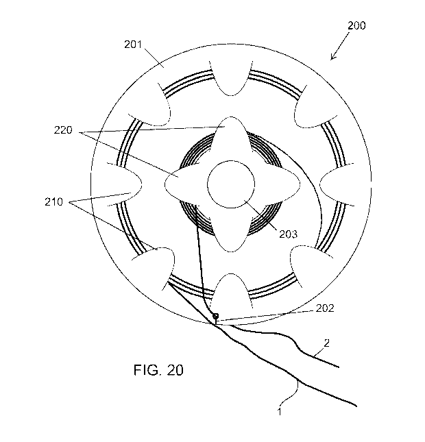
[0047] FIG. 20 depicts a planar suture-wire management device, in accordance
with some
embodiments of the invention.
[0048] FIGS. 21-22 depicts a ring enclosure suture-wire management device, in
accordance
with some embodiments of the invention.
[0049] FIGS. 23-24 depicts a delivery catheter handle with integrated suture-
wire
management device, in accordance with some embodiments of the invention.
[0050] FIGS. 25-26 depicts a sleeve type suture-wire management device, in
accordance
with some embodiments of the invention.
DETAILED DESCRIPTION OF THE INVENTION
[0051] Although the disclosure hereof is detailed and exact to enable those
skilled in the art
to practice the invention, the physical embodiments herein disclosed merely
exemplify the
invention which may be embodied in other specific structures. While the
preferred
embodiment has been described, the details may be changed without departing
from the
invention, which is defined by the claims.
[0052] FIG. 1A shows an example embodiment of a catheter-based delivery system
100 in
accordance with aspects of the invention. The delivery system utilizes a pair
of magnetic
11
CA 03128030 2021-07-27
WO 2020/160218
PCT/US2020/015810
catheters that are advanced from separate vascular access points and
magnetically coupled
across a tissue within the heart. The pair of catheters include a great
cardiac vein (GCV)
anchor delivery catheter 50 which is introduced from the jugular vein and
advanced along a
superior vena cava (SVC) approach to the GCV, and a left atrial (LA) catheter
60, which is
introduced at the femoral vein and introduced along an inferior vena cava
(IVC) approach,
across the inter-atrial septum and into the left atrium. Each catheter
includes a magnetic head
along a distal portion thereof (magnetic head 52 of catheter 50 and magnetic
head 62 of
catheter 60) such that when magnetically coupled, the catheters provide a
stable region to
facilitate penetration of a tissue wall between the LA and GCV and subsequent
advancement
of the puncturing guidewire 1 through the GCV catheter 50 and into the LA
catheter 60.
Notably, a trailing end of the puncturing wire needle guidewire 1 is attached
to one end of a
suture bridging element 1 (e.g. suture), the other end of which is attached to
posterior anchor
18 disposed on the distal portion of GCV catheter 50. GCV delivery catheter 50
includes a
proximal catheter handle 400 with integrated suture-wire management device for
storing and
managing excess suture-wire during the implant deployment procedures described
herein. As
can be seen in FIG. 1B, a loop of excess bridging element extends proximally
outside of the
catheter lumen, which is managed by the suture-wire management device in the
catheter
handle, as described herein.
[0053] Such a configuration allows the bridging element 12 to be advanced
across the left
atrium by advancing the puncturing needle wire 1 through the LA catheter 60 to
exit from the
femoral vein, while the magnetic heads remain magnetically coupled to each
other, as shown
in FIG. 13. As can be understood by referring to FIG. 13, the penetrating
guidewire 1 has a
length greater than the combined length of the catheters such that the
guidewire 1 can be
manually advanced externally from one vascular access point until the
guidewire 1 exits the
other vascular access point due to the stiffness of the guidewire 1. The
guidewire 1 can be
further retracted after exiting so as to pull the attached suture 2 through
the vascular path until
the suture 2 also exits the same vascular access point. This deployment
approach can be
understood further by referred to the following figures, which describe the
implant and
associated components in more detail as well as conventional approaches of
delivery and
deploying such implants.
12
CA 03128030 2021-07-27
WO 2020/160218
PCT/US2020/015810
I. Heart Implants for Treatment/Repair of a Heart Valve Annulus
A. Implant Structure
[0054] FIGS. 3A-3B show embodiments of an implant 10 that is sized and
configured to
extend across the left atrium in generally an anterior-to-posterior direction,
spanning the
mitral valve annulus. The implant 10 comprises a spanning region or bridging
element 12
(formed by a portion of suture 2), the bridging element 12 having a posterior
anchor region
14 and an anterior anchor region 16. The posterior anchor region 14 is sized
and configured
to allow the bridging element 12 to be placed in a region of atrial tissue
above the posterior
mitral valve annulus. The anterior anchor region 16 is sized and configured to
allow the
bridging element 12 to be placed, upon passing into the right atrium through
the septum,
adjacent tissue in or near the right atrium. For example, as is shown in FIGS.
3A-3B, the
anterior anchor region 16 may be adjacent or abutting a region of fibrous
tissue in the
interatrial septum. As shown, the anchor site 16 is desirably superior to the
anterior mitral
annulus at about the same elevation or higher than the elevation of the
posterior anchor
region 14. In the illustrated embodiment, the anterior anchor region 16 is
adjacent to or near
the inferior rim of the fossa ovalis. Alternatively, the anterior anchor
region 16 can be
located at a more superior position in the septum, e.g., at or near the
superior rim of the fossa
ovalis. The anterior anchor region 16 can also be located in a more superior
or inferior
position in the septum, away from the fossa ovalis, provided that the anchor
site does not
harm the tissue in the region. Alternatively, the anterior anchor region 16,
upon passing
through the septum into the right atrium, may be positioned within or
otherwise extend to one
or more additional anchors situated in surrounding tissues or along
surrounding areas, such as
within the superior vena cava (SVC) or the inferior vena cava (IVC).
[0055] In use, the spanning region or bridging element 12 can be placed into
tension
between the two anchor regions 14 and 16. The implant 10 thereby serves to
apply a direct
mechanical force generally in a posterior to anterior direction across the
left atrium. The
direct mechanical force can serve to shorten the minor axis (along line P-A in
FIG. 2E) of the
annulus. In doing so, the implant 10 can also reactively reshape the annulus
along its major
axis (line CM-CL in FIG. 2E) and/or reactively reshape other surrounding
anatomic
structures. The mechanical force applied by the implant 10 across the left
atrium can restore
to the heart valve annulus and leaflets a more normal anatomic shape and
tension. The more
13
CA 03128030 2021-07-27
WO 2020/160218
PCT/US2020/015810
normal anatomic shape and tension are conducive to coaptation of the leaflets
during late
ventricular diastole and early ventricular systole, which, in turn, reduces
mitral regurgitation.
[0056] In its most basic form, the implant 10 is made from a biocompatible
metallic or
polymer material, or a metallic or polymer material that is suitably coated,
impregnated, or
otherwise treated with a material to impart biocompatibility, or a combination
of materials.
[0057] In some embodiments, the suture-wire includes a penetrating wire
section having
sufficient stiffness and compressive strength to penetrate tissue, which can
be formed of a
metal, such as Nitinol or stainless steel, or any suitable material, and
further includes a more
flexible, less stiff section that defines the bridging element, typically a
substantially inelastic
material, such as a thread-like or suture, or any suitable material.
B. The Posterior Anchor Region
[0058] The posterior anchor region 14 is sized and configured to be located
within or at the
left atrium at a supra-annular position, i.e., positioned within or near the
left atrium wall
above the posterior mitral annulus. In the illustrated embodiment, the
posterior anchor region
14 is shown to be located generally at the level of the great cardiac vein,
which travels
adjacent to and parallel to the majority of the posterior mitral valve
annulus. This extension
of the coronary sinus can provide a strong and reliable fluoroscopic landmark
when a radio-
opaque device is placed within it or contrast dye is injected into it. The
great cardiac vein
also provides a site where relatively thin, non-fibrous atrial tissue can be
readily augmented
.. and consolidated. To enhance hold or purchase of the posterior anchor
region 14 in what is
essentially non-fibrous heart tissue, and to improve distribution of the
forces applied by the
implant 10, the posterior anchor region 14 may include a posterior anchor 18
placed within
the great cardiac vein and abutting venous tissue.
C. The Anterior Anchor Region
[0059] The anterior anchor region is sized and configured to allow the
bridging element 12
to remain firmly in position adjacent or near the fibrous tissue and the
surrounding tissues in
the right atrium side of the atrial septum. The fibrous tissue in this region
provides superior
mechanical strength and integrity compared with muscle and can better resist a
device pulling
through. The septum is the most fibrous tissue structure in its own extent in
the heart.
14
CA 03128030 2021-07-27
WO 2020/160218
PCT/US2020/015810
[0060] As shown in FIGS. 3A-3B, the anterior anchor region 16 passes through
the septal
wall at a supra-annular location above the plane of the anterior mitral valve
annulus. The
supra-annular distance on the anterior side can be generally at or above the
supra-annular
distance on the posterior side. The anterior anchor region 16 is shown at or
near the inferior
rim of the fossa ovalis, although other more inferior or more superior sites
can be used within
or outside the fossa ovalis, taking into account the need to prevent harm to
the septal tissue
and surrounding structures.
[0061] FIGS. 10A and 10B show the anterior anchor region including a septal
member 30.
The septal member 30 may be an expandable device and also may be a
commercially
available device such as a septal occluder, e.g., Amplatzer PFO Occluder (see
FIGS. 5A-
5B). The septal member 30 preferably mechanically amplifies the hold or
purchase of the
anterior anchor region 16 in the fibrous tissue site.
D. Orientation of the Bridging Element
[0062] In the embodiments shown in FIGS. 3A-3B, the implant 10 is shown to
span the left
atrium beginning at a posterior point of focus superior to the approximate mid-
point of the
mitral valve annulus, and proceeding in an anterior direction in a generally
straight path
directly to the region of anterior focus in the septum. The spanning region or
bridging
element 12 of the implant 10 may be preformed or otherwise configured to
extend in this
essentially straight path above the plane of the valve, without significant
deviation in
elevation toward or away from the plane of the annulus, other than as dictated
by any
difference in elevation between the posterior and anterior regions of
placement. It is
appreciated that such implants can include bridging member with lateral or
medial deviations
and/or superior or inferior deviations and can include bridging members that
are rigid or
semi-rigid and/or substantially fixed in length.
E. Posterior and Anterior Anchors
[0063] It is to be appreciated that an anchor as described herein, including a
posterior or
anterior anchor, describes an apparatus that may releasably hold the bridging
element 12 in a
tensioned state. As can be seen in FIGS. 4A-4B, anchors 20 and 18 respectively
are shown
releasably secured to the bridging element 12, allowing the anchor structure
to move back
and forth independent of the inter-atrial septum and inner wall of the great
cardiac vein
during a portion of the cardiac cycle when the tension force may be reduced or
becomes zero.
CA 03128030 2021-07-27
WO 2020/160218
PCT/US2020/015810
Alternative embodiments are also described, all of which may provide this
function. It is also
to be appreciated that the general descriptions of posterior and anterior
anchors are non-
limiting to the anchor function, i.e., a posterior anchor may be used
anterior, and an anterior
anchor may be used posterior. Thus, the bridging-element managed by the suture-
wire
management device may be attached to any type of anchor as desired.
[0064] FIGS. 6A-6B show perspectives views of an example locking bridge stop
20. Each
bridge stop 20 includes a fixed upper body 302 and a movable lower body 304
and positioned
circumjacent a tubular shaped rivet 306. The upper body 302 and lower body 304
are held in
position by the rivet head 308 and base plate 310 having a predetermined inner
diameter 312,
sized to allow bridge stop 300 to be installed over a guide wire. A spring,
such as spring
washer 314, is positioned circumjacent rivet 306 and between rivet head 308
and upper body
302, and applies an upward force on lower body 304, which is movable between a
bridge
unlocked position (see FIG. 6A), and a bridge locked position (see FIG. 6B).
[0065] FIGS. 7A-7B show alternative heart implants suitable for delivery with
the methods
and delivery systems described herein. FIG. 7A shows an implant 10' having a T-
shaped
posterior anchor 18 in the great cardiac vein and T-shaped anterior anchor 70.
The anterior T-
shaped bridge stop 75 may be of a construction of any of the T-shaped bridge
stop
embodiments described. The T-shaped member 75 includes a lumen 75 extending
through
the T-shaped member 75 perpendicular to the length of the T-shaped member. The
bridging
element 12 may be secured by a free floating bridge stop as previously
described. FIG. 7B
shows an implant 10" having a T-shaped posterior anchor 18 in the great
cardiac vein and a
lattice style anterior anchor 76. The lattice 77 is positioned on the septal
wall at or near the
fossa ovalis. Optionally, lattice 77 may include reinforcement strut 78 to
distribute tension
forces over a greater area on the septal wall. It is appreciated that various
other such implants
could be devised that utilized the same concepts as in the above described
implants for
delivery and deployment with the systems and methods described herein.
[0066] FIGS. 8A-8B show alternative methods of connecting the bridging element
12 to a
T-shaped posterior anchor. FIG. 8A shows a T-shaped member 18 where the
bridging
element 12 is wound around a central portion of the T-shaped member. The
bridging element
12 may be secured by adhesive 712, knot, or a securing band placed over the
bridging
element 12, for example. Alternatively, the bridging element 12 may first be
threaded
through a lumen 714 extending through the T-shaped posterior anchor 18
perpendicular the
16
CA 03128030 2021-07-27
WO 2020/160218
PCT/US2020/015810
length of the T-shaped member. The bridging element 12 may then be wound
around the T-
shaped member, and secured by adhesive 712, securing band, or knot, for
example. FIG. 8B
shows a T-shaped member 18 where the bridging element 12 is welded or forged
to a plate
716. The plate 716 may then be embedded within the T-shaped member 710. It is
appreciated that various other couplings could be used to secure the bridging
element 12 and
posterior anchor 18 and facilitate delivery with the systems and methods
described herein.
[0067] FIGS. 9A-9B depict alternative anchors suitable for use as posterior
anchors within
a heart implant. FIG. 9A is a perspective view of a T-shaped anchor 18' that
includes an
intravascular stent 80 and, optionally, a reinforcing strut 81. FIG. 9B
depicts a T-shaped
anchor 18" that includes a flexible tube 90 having a predetermined length,
e.g., three to eight
centimeters, and an inner diameter 91 sized to allow at least a guide wire to
pass through. The
tube 90 is preferably braided, but may be solid as well, and may also be
coated with a
polymer material. It is appreciated that various other type of anchors could
be used.
General Methods of Delivery and Implantation
[0068] The implant systems 10 described herein lend themselves to implantation
in a heart
valve annulus in various ways. Preferably, the implant systems 10 are
implanted using
catheter-based technology via a peripheral venous access site, such as in the
femoral or
jugular vein (via the IVC or SVC) under image guidance, or trans-arterial
retrograde
approaches to the left atrium through the aorta from the femoral artery also
under image
guidance. As previously described, the implants 10 comprise independent
components that
are assembled within the body to form an implant, and delivered and assembled
from an
exterior the body through interaction of multiple catheters.
A. Conventional Delivery Approach
[0069] FIGS. 10A-12D show deployment of an implant 10 of the type shown in
FIGS. 3A-
3B by a percutaneous, catheter-based procedure, under image guidance using
conventional
methods into the femoral or jugular vein, or typically, a combination of both,
such as any of
those described in U.S. Patent Publication 2017/0055969.
[0070] Percutaneous vascular access is achieved by conventional methods into
the femoral
or jugular vein, or typically, a combination of both. As shown in FIG. 10A,
under image
guidance, a first catheter, or GCV catheter 40, is advanced into the great
cardiac vein from a
superior vena cava (SVC) route accessed from a neck vein (e.g. jugular vein)
along a GCV
17
CA 03128030 2021-07-27
WO 2020/160218
PCT/US2020/015810
guidewire 1. As shown in FIG. 10B, the LA catheter 60 is advanced from the
right atrium via
an inferior vena cava (IVC) accessed from a femoral vein, through the septum,
typically at or
near the fossa ovalis, and into the left atrium. The septal wall at the fossa
ovalis is punctured
with a trans-septal needle and a LA guide wire 74 is advanced through the
septum into the
left atrium. Typically a large bore (12-16 French) hemostasis sheath with a
"Mullins" shape
is placed in the LA to act as a conduit for placement for subsequent devices
to placed or
removed from the LA without injuring the tissues along the pathway to or in
the LA. The LA
catheter 60 is then advanced into the left atrium through this sheath.
[0071] Each of catheters 40, 60 include a magnetic head 42, 62, respectively,
disposed
along a distal portion thereof, the magnetic heads being configured to
facilitate magnetic
coupling when positioned at a desired orientation and position across a tissue
wall between
the left atrium and the great cardiac vein. As shown in FIGS. 11A-11B, LA
catheter 60
includes distal magnetic head having a N-S magnetic poles arranged axially
along the
catheter, while the GCV catheter 40 includes distal magnetic head having N-S
magnetic poles
.. arranged laterally relative a longitudinal axis of the catheter. This
arrangement facilitate a
transverse or perpendicular magnetic coupling between the respective
catheters, as shown in
FIGS. 11B-11C so as to allow passage of a penetrating element or guidewire,
typically from a
channel within one magnetic head into a corresponding channel of the other
magnetic head.
In this approach, the penetrating element is a puncturing guidewire 1 with a
sharpened distal
end. Typically, the puncturing guidewire 1 is advanced through a curved
channel 43 within
the magnetic head 42 of the GCV catheter 40 and enters a funnel-shaped channel
67 of
magnetic head 62 of LA catheter 60. While in this embodiment, the magnetic
head of GCV
catheter 40 has a single magnet, it is appreciated that various other
embodiments can include
a magnetic head having additional magnets oriented to facilitate a desired
alignment, for
example, a three-magnet head in which a center magnet has magnetic poles
oriented laterally
to an axis of the catheter between two magnets with poles oriented axially,
such as that
shown in U.S. Patent Publication 2017/0055969.
[0072] Next, as shown in FIG. 12A, the penetrating guidewire is advanced
through the LA
catheter 60 until it exits the femoral artery access point at the groin. The
left atrium magnetic
catheter A is then replaced by a very long exchange catheter 28, which is
carefully pushed
across the puncture site along the great cardiac vein to interface with the
great cardiac vein
magnetic catheter 40. The exchange catheter 28 is pushed simultaneously with
removing the
great cardiac vein magnetic catheter 40 to avoid exposing the puncturing wire
to tissue.
18
CA 03128030 2021-07-27
WO 2020/160218
PCT/US2020/015810
Exposure of the puncturing wire during this process could easily slice through
tissue should
the wire move or become tensioned during removal or replacement of one of the
catheters.
This process typically requires two operators, one operator pushes the
exchange catheter
while the other operator simultaneously removes the great cardiac vein
magnetic catheter,
often while utilizing visualization techniques to ensure the two catheters
remain interfaced
and the puncturing wire remains covered. Once the exchange catheter 28 is
placed from neck
to groin, the puncturing wire is removed and replaced with a left atrial
extension guidewire
74, as shown in FIG. 12B.
[0073] Next, extension guide wire 74 is gently retracted, causing the bridging
element 12 to
follow through the vasculature structure. If the optional exchange catheter 28
is used (as
shown in FIGS. 12A-12B), the extension guide wire 74 retracts through the
lumen of the
exchange catheter 28 without injuring tissues. The extension guide wire 74 is
completely
removed from the body at the femoral vein, leaving the bridging element 12
extending from
exterior the body (preferably at the femoral sheath), through the vasculature
structure, and
again exiting at the superior vena cava sheath. The extension guide wire 74
may then be
removed from the bridging element 12 by cutting or detaching the bridging
element 12 at or
near the interface coupling 800 between the bridging element 12 and extension
guide wire 74.
The anterior end of the extension guidewire 74 is attached to one end of the
bridging element
(e.g. suture material) while the other end of the bridging element is attached
to the posterior
anchor, which is retained within a posterior anchor delivery catheter 115. As
can be seen in
FIG. 12B, the extension guide wire 74 is gently retracted, causing the
bridging element 12 to
follow into the exchange catheter 28 and through the vasculature structure.
[0074] Posterior anchor 120 disposed within deployment catheter 24 is
connected to the
trailing end of bridging element 12 (which is the trailing portion of suture
section 2 of suture-
wire element) extending from the superior vena cava. While a T-shaped anchor
is shown
here, it is appreciated that various other types of posterior anchors can be
used (e.g. stent,
half-stent). The deployment catheter 24 is then positioned onto or over the
GCV guide wire
54 and abutted against exchange catheter 28. The two-operator pushing and
pulling process is
repeated pushing the posterior anchor delivery catheter 115 while
simultaneously removing
the exchange catheter 28 so as to position the posterior anchor within the
great cardiac vein
and the bridging element extends across the left atrium. Optionally, the
bridging element 12
may be pulled from the femoral vein region, either individually, or in
combination with the
deployment catheter 24, to facilitate advancement of the posterior anchor 120
and bridging
19
CA 03128030 2021-07-27
WO 2020/160218
PCT/US2020/015810
element into position in the great cardiac vein and across the left atrium.
The GCV guide wire
54 is then retracted letting the T-shaped anchor 120 separate from the GCV
guide wire 54 and
deployment catheter 24. Preferably under image guidance, and once separation
is confirmed,
the bridging element 12 is gently pulled to position the T-shaped anchor 120
in abutment
against the venous tissue within the great cardiac vein and centered over the
GCV access
lumen 115. The deployment catheter 24 and exchange catheter 28 may then be
removed. The
T-shaped anchor 120 with attached bridging element 12 remain within the great
cardiac vein.
The length of bridging element 12 extends from the posterior T-shaped anchor
120, through
the left atrium, through the fossa ovalis, through the vasculature, and
preferably remains
accessible exterior the body. The bridging element 12 is now ready for the
next step of
establishing the anterior anchor region 16, as previously described and as
shown in FIGS.
16C-16D.
[0075] Once the posterior anchor region 14, bridging element 12, and anterior
anchor
region 16 configured as previously described, a tension is placed on the
bridging element 12.
The implant 10 and associated regions may be allowed to settle for a
predetermined amount
of time, e.g., five or more seconds. The mitral valve and mitral valve
regurgitation are
observed for desired therapeutic effects. The tension on the bridging element
12 may be
adjusted until a desired result is achieved. The anchor 20 is then secured the
bridging
element 12 by use of a locking bridge stop 30 when the desired tension or
measured length or
degree of mitral regurgitation reduction is achieved.
B. Alternative Methods of Delivery and Associated Catheter Systems
[0076] In another aspect, an alternative anchor delivery catheter allows for
improved
delivery and deployment of the above-described implant with fewer catheters
and improved
ease of use as compared to the conventional approach described above. In some
embodiments, the catheter systems includes an anchor delivery catheter having
a distal
magnet portion that facilitates access to a heart chamber from within an
adjacent vasculature
by passage of a penetrating guidewire to a magnetically couple catheters
within the heart
chamber. In some embodiments, the anchor delivery catheter is configured for
delivery of
the bridging element across the heart chamber (e.g. left atrium), once access
is achieved, and
subsequent deployment of the anchor within the vasculature (e.g. great cardiac
vein). As
described above, the bridging element is defined by the suture section, which
is attached to
the trailing end of the penetrating wire section while the other end of the
suture section is
CA 03128030 2021-07-27
WO 2020/160218
PCT/US2020/015810
attached to the posterior anchor disposed on a distal portion of the delivery
catheter. This
allows the bridging element to be advanced through the penetration between the
heart
chamber and vasculature by continued advancement of the suture-wire element
from one
vascular access point (e.g. jugular vein) to exit the body at the second
vascular access point
(e.g. femoral vein).
[0077] In some embodiments, for example as shown in FIG. 13, the above
described
anchor delivery is a GCV catheter 50 for delivery of the posterior anchor 18
within the GCV.
Catheter 50 preferably includes a magnetic or ferromagnetic head 52 positioned
along a distal
portion of the catheter shaft. Optionally, a hub or handle with integrated
suture-wire
management can be positioned on the proximal end of the catheter. The catheter
shaft may
include a proximal section that is generally stiff to allow for torquability
of the shaft, which
can be of a solid or braided construction. The proximal section includes a
predetermined
length (e.g., fifty centimeters or more), to allow positioning of the shaft
within the
vasculature structure. A distal section, along which the distal portion is
defined, may be
generally flexible to allow for steerability within the vasculature or heart
chamber. An inner
diameter or lumen of the catheter shaft is preferably sized to allow passage
of a GCV guide
wire 15, and a penetrating guide wire as well as a bridging element. The GCV
catheter 50
preferably includes a radio-opaque marker to facilitate adjusting the catheter
under image
guidance to align with the LA catheter 60. The magnetic or ferromagnetic head
52 is
preferably polarized to magnetically attract or couple the distal end of the
LA catheter 60, as
described previously. Magnetic head 52 includes a guide channel formed therein
to facilitate
passage of the penetrating guidewire through the channel and into a
corresponding channel in
the magnetic head of the LA catheter 60.
[0078] Similar to the GCV catheter 50 the LA catheter 60 preferably includes a
magnetic or
ferromagnetic head 62 positioned on a distal end thereof The catheter shaft
may include a
proximal and distal sections similar to those of catheter 50 described above.
An inner
diameter or lumen of the catheter shaft is preferably sized to allow passage
of an LA guide
wire 74, and additionally may accept the penetrating needle wire 1 passed from
the GCV and
subsequently the bridging element 12 attached thereto. The magnetic or
ferromagnetic head
62 of the LA catheter 60 is polarized to magnetically attract or couple the
distal end of the
GCV catheter, for example, as shown in FIGS. 11A-11C.
21
CA 03128030 2021-07-27
WO 2020/160218
PCT/US2020/015810
[0079] While a particular configuration of magnetic heads are described above,
it is
appreciated that various other magnetic head configurations could be used, for
example the
configuration in FIG. 17 or any of these described in U.S. Patent Publication
2017/0055969.
1. Exemplary Implantation Methods
[0080] Access to the vascular system is commonly provided through the use of
introducers
known in the art. A 16F or less hemostasis introducer sheath (not shown), for
example, may
be first positioned in the superior vena cava (SVC), providing access for the
GCV catheter
50. A second 14F or less introducer sheath (not shown and described above) may
then be
positioned in the right femoral vein, providing access for the LA catheter 60.
Access at both
the SVC and the right femoral vein, for example, also allows the implantation
methods to
utilize a loop guide wire. For instance, in a procedure to be described later,
a loop guide wire
is generated by advancing a LA guide wire through the vasculature until it
exits the body and
extends external the body at both the superior vena cava sheath and femoral
sheath. The LA
guide wire may follow an intravascular path that extends at least from the
superior vena cava
sheath through the interatrial septum into the left atrium and from the left
atrium through
atrial tissue and through a great cardiac vein to the femoral sheath.
[0081] FIGS. 14A-16D illustrate a method of implantation utilizing a magnetic
anchor
delivery catheter in accordance with aspects of the invention. FIGS. 14A-14B
depict
positioning of the GCV anchor delivery catheter 50 within the great cardiac
vein adjacent a
posterior annulus of the mitral valve. As shown in FIG. 14A, under image
guidance, the
GCV guide wire 15 (e.g. a 0.035 inch guidewire), is advanced into the coronary
sinus to the
great cardiac vein along an SVC approach.
[0082] As shown in FIG. 14B, the GCV catheter 50 is advanced over the GCV
guide wire
15 so that the distal magnetic head 52 and posterior anchor 18 are positioned
at or near a
desired location in the great cardiac vein, for example near the center of the
posterior leaflet
or posterior mitral valve annulus. The desired position for the GCV catheter
50 may also be
viewed as approximately 2 to 6 centimeters from the anterior intraventricular
vein takeoff.
[0083] As shown in FIG. 14C, the LA catheter 60 is then deployed in the left
atrium. From
the femoral vein, under image guidance, the LA guide wire 16 (e.g., a 0.035
inch guidewire)
is advanced into the right atrium. A 7F Mullins dilator with a trans-septal
needle (not shown)
can be deployed into the right atrium. The septal wall at the fossa ovalis can
be punctured
22
CA 03128030 2021-07-27
WO 2020/160218
PCT/US2020/015810
with a trans-septal needle and the guide wire 16 is advanced into the left
atrium. The trans-
septal needle is then removed and the dilator is advanced into the left
atrium. The Mullins
system is removed and then replaced with a 12F or other appropriately sized
Mullins system.
The 12F Mullins system is positioned within the right atrium and extends a
short distance
.. into the left atrium and the LA catheter 60 is advanced into the left
atrium. After
advancement of the LA catheter 60 into the left atrium, a distal magnetic head
62 of the
catheter is positioned in the region adjacent the great cardiac vein so as to
magnetically
couple with the magnetic head 52 of GCV magnetic catheter 50, as shown in
FIGS. 11A. The
magnetic heads automatically align the lumens of the LA catheter 60 and GCV
catheter 50.
[0084] As shown in FIG. 14D, once magnetically coupled, puncturing wire 1 is
advanced
through GCV catheter 50 to penetrate the tissue wall between the great cardiac
vein and the
left atrium and enters a lumen of the magnetic head 62 of LA catheter 60. The
operator
continues to advance the puncturing guidewire 1 through a lumen of the LA
catheter 60 until
the guidewire exits the body (e.g. at the groin). Since the trailing end of
the puncturing wire
section 1 is attached to the one end of the suture section 2, the other end of
the suture section
being attached to posterior anchor 18, once the puncturing guidewire 1 exits
the proximal end
of the LA catheter 60, the puncturing wire 1 can be pulled proximally from the
LA catheter
60 thereby pulling the suture section 2 through the GVC catheter 50, across
the left atrium
within the LA catheter 60 and through the vasculature to exit the body at the
groin, all while
the LA catheter 60 and the GVC catheter 50 remain magnetically coupled. This
approach
ensures the puncturing wire 1 and the suture section 2 remain covered while
the being drawn
through the vasculature over the delicate tissues of the heart, which avoids
cutting or slicing
the tissue with the bridging element and further avoids the laborious pushing
and pulling
procedure and use of an exchange catheter described in the conventional
approach.
[0085] As shown in FIG. 15A, the suture section 2 extends from the posterior
anchor 18
disposed within the distal portion of the GCV catheter 50, spans the left
atrium and extends
through the LA catheter 60 and exits the body at the femoral vein. The
operator can gently
tug the suture section 2 to remove any slack from the system and ensure it is
properly
positioned. In some embodiments, this action can also facilitate release of
the posterior
anchor 18 from the GCV delivery catheter 50. The LA catheter 60 can be
decoupled from the
GCV catheter 50 and withdrawn while the bridging element remains in place, as
shown in
FIG. 15B. Optionally, the LA catheter 60 can remain within the left atrium
extending
through the septum until the posterior anchor 18 is fully deployed.
23
CA 03128030 2021-07-27
WO 2020/160218
PCT/US2020/015810
[0086] As shown in FIG. 15C, the GCV catheter 50 is adjusted, if needed, to
position the
posterior anchor 18 along the penetration for subsequent release from the
catheter. The
posterior anchor 18 can be released from the GCV delivery catheter 50 by
proximally
retracting the GCV guidewire 15 extending through the posterior anchor 18.
Optionally, the
catheter configuration can include a releasable coupling feature, such as a
tether 903, that
secures the posterior anchor 18 to the distal portion of GCV catheter 50 and
extends from the
proximal end so that an operator can proximally pull the tether to release the
posterior anchor
18. Once the posterior anchor 18 is deployed, the GCV catheter 50 and GCV
guidewire can
be removed, as shown in FIG. 15D.
[0087] As shown in FIG. 16A, the posterior anchor 18 deployed within the great
cardiac
vein is attached to the suture section 2 spanning the left atrium and
extending through the
vasculature along the IVC route to exit from the femoral vein at the groin.
Since the suture
section 2 is not yet tensioned, there is little likelihood of cutting or
damage to tissues at this
point. Next, as shown in FIG. 16B, an anterior anchor delivery catheter 26 is
advanced along
the suture section 2 with the anterior anchor mounted with the bridging
element passing
through its central hub the delivery catheter 26 having an anterior anchor 30,
collapsed inside
the delivery sheath, disposed in a distal portion thereof, the bridging
element passing through
its central hub. The collapsed anterior anchor is guided to the FO or other
suitable location
along the septal wall and deployed, such as shown in FIG. 5B.
[0088] As shown in FIG. 16C, the anterior anchor 30 is deployed along the
septal wall with
a proximal locking bridge stop 20 through the delivery sheath. The length of
the bridging
element 12 can then be incrementally adjusted and held in place by the bridge
lock 20 upon
each adjustment until observation of the heart pumping indicates improved
valve function.
The excess bridging element 12 can then be cut with a cutting element of the
catheter, or by
use of a separate cutting catheter advanced along the bridging element 12. The
LA delivery
catheter 60 can then be removed, leaving the fully deployed implant 10 in
place within the
heart, as shown in FIG. 16D.
2. Exemplary Catheter Configurations
[0089] As discussed previously, one purpose of some such delivery catheter
configurations
is to facilitate deployment of the posterior anchor while keeping the bridging
element totally
within the protection of the magnetically connected catheters by combining the
magnets and
keeping the posterior anchor on one delivery catheter in the great cardiac
vein. Examples of
24
CA 03128030 2021-07-27
WO 2020/160218
PCT/US2020/015810
such delivery catheter configurations are detailed below. It is appreciated
that any of the
aspects or features described in certain embodiments may be utilized in
various other
embodiments in accordance with the concepts described herein.
[0090] FIG. 17 shows an exemplary anchor delivery catheter configuration in
accordance
.. with aspects of the invention. In particular, the catheter configuration
allows for
magnetically coupling with a corresponding catheter to establish access within
a heart
chamber from adjacent vasculature and delivering a heart implant in accordance
with aspect
of the invention. These example delivery catheters are configured for use
within a GCV
catheter 50, with the example delivery and deployment methods depicted above.
It is
appreciated that the following catheter configurations can include any of the
various aspect
described herein (e.g. length, materials, dimensions, etc.), but are not
limited to the aspects
described herein and could be configured as needed for a particular use or
anatomy.
[0091] FIG. 17 shows a distal portion of a delivery catheter configuration 700
that includes
a guidewire lumen 701a extending longitudinally to facilitate advancement of
the catheter
along a guidewire 1 positioned in the vasculature of the patient (e.g. within
the great cardiac
vein when the catheter configuration is utilized in a GVC anchor delivery
catheter). The
catheter can further include a puncture wire lumen 701b dimensioned to allow
passage of the
puncture wire section 1 and subsequent passage of suture section 2 attached
thereto. The
catheter includes a magnetic head 702 configured to magnetically couple with a
magnetic
.. head 722 of catheter 720 through a tissue wall therebetween. Magnetic head
702 is defined
so that the magnetic poles of the magnetic heads are disposed laterally
relative a longitudinal
axis of the catheter so as to couple in a perpendicular orientation with
magnetic head 722 of
magnetic catheter 720, in a similar fashion as in FIG. 11C. The magnetic head
702 further
includes a guide channel 703 defined to steer puncturing needle wire 1 upward
through an
exit hole 704 to direct the sharped distal tip 55 (e.g. flat tip) of the
puncturing needle wire
section 1 through the tissue wall and into magnetic head 722 of catheter 720.
The dashed
vertical line in FIG. 17 represents the point at which the delivery catheter
extends outside the
body. In any of these embodiments, the suture section 2 and puncturing needle
wire 1 can
extend through a Y-arm connector to facilitate independent manual control of
the guidewire
.. and the puncturing wire 1/suture section 2. In some embodiments the excess
suture-wire
(including the transition point between the needle wire section 1 and the
suture section 2) can
be wound within a suture-wire management device, which can be separate or
incorporated
into the catheter handle, as described further below. (The catheter shaft
extending between
CA 03128030 2021-07-27
WO 2020/160218
PCT/US2020/015810
the distal end portion and the Y-arm connector is not shown). In such
embodiments, the
length of the puncturing wire 1 is greater than the sum of both magnetic
catheters, and the
length of suture section 2 is at least long enough to extend from the
posterior anchor to the
second access site, so that when the puncturing wire is pulled from the second
access site it
pulls the suture section 2 out the second access site. In some embodiments,
the suture section
may be long enough that it remains outside the first access site until it is
pulled out of the
second access site, which is desirable in the unlikely event that the suture
becomes
disconnected from the needle wire section before the suture section is pulled
out the second
access site so that the operator may retrieve it by pulling on the proximal
portion still out of
the body. In this instance, the suture section would need to be as long as the
sum of the
length of the second catheter 60 and twice the length of the delivery catheter
50 since it needs
to switch back as described above.
[0092] Catheter 700 includes a catheter shaft 705 along its length, which can
be formed of
any suitable material, to facilitate advancement of the catheter through the
vasculature. As
shown, the magnetic head 702 is formed with a notch or contoured recess in one
side, which
in this embodiment is opposite the exit hole 704, although could be located in
any suitable
location in embodiments. The notch, recess or groove 709 is configured to
allow passage of
the guidewire 1 and/or to receive at least a portion of posterior anchor 718.
In this
embodiment, posterior anchor 718 is defined as an elongate member having a
longitudinal
lumen through which the guidewire 1 extends. It is appreciated that a
posterior anchor
having a longitudinal lumen through which the guidewire 1 extends could be
utilized in any
of the embodiments described herein. It is further appreciated that the
posterior anchor 718
could be positioned partly extending within a recess of the magnetic head,
extending distally
of the magnetic head (as shown) or proximally, or could extend proximally and
proximally
and distally of the magnetic head or could be disposed entirely proximal or
entirely distal of
the magnetic head. An outer jacket 706 covers the magnetic head 702 and
includes an
opening over exit hole 704 to allow passage of the penetrating wire section 1
therethrough.
Typically, the outer jacket 706 is formed for a flexible polymer material and
is defined to
form a smooth interface with the catheter shaft 705. The outer jackets helps
maintain the
magnetic head 702 within the catheter and may extend at least partly over the
posterior
anchor 718 to help retain the posterior anchor 718 during advancement of the
catheter
through the vasculature. It is appreciated that the suture-wire management
device can be
used with different types of deployment system, including any of those
described herein and
26
CA 03128030 2021-07-27
WO 2020/160218
PCT/US2020/015810
any of those described in U.S. Patent Application No. 16/056,220 filed
08/06/2018, the entire
contents of which are incorporated herein for all purposes.
3. Bridge Cutting Catheters
[0093] Delivery systems can further include a bridge element cutting device
either
incorporated into the catheter or as a separate catheter, examples of which
are shown in
FIGS. 18A-19C. FIG. 18A shows abridge cutting catheter 810 to facilitate
removal of a
deployed implant. Bridge cutting catheter 810 includes a curve tipped stylet
811 within an
inside diameter of the catheter shaft to facilitate steering of the cutting
tip to suture bridge 12.
The cutting tip includes a cutting blade 812 and a capture feature 813. The
cutting blade 812
includes a sharpened cutting edge along one longitudinally extending side and
an angled
proximal facing end surface. The capture feature 813 is a loop that is angled
so as to capture
the bridging element 12 and direct the bridging element to the cutting edge
when the cutting
catheter is proximally retracted, thereby cutting the bridging element.
[0094] FIGS. 18B-18C shows a bridging cutting catheter 820 with suture grip
824 for
cutting the bridging element and removing excess suture after cutting, in
accordance with
aspects of the invention. Similar to the bridge cutting catheter in FIG. 18A,
the catheter
includes a cutting head with a cutting blade and a capture loop 823 configured
to operate in a
similar manner as described above. This catheter further includes a suture
grip 824 to
facilitate removal of excess suture. The suture grip 824 can be configured to
hold the
bridging element (e.g. by friction fit, or between opposable members) and to
wind up excess
bridging element by rotation of an element extending through a shaft of the
catheter. After
initial cutting of the bridging element 12 with the cutting element, as shown
in FIG. 18B,
suture grip 824 is actuated by rotation of a rotatable member extending
through the shaft,
which winds up excess suture and also moves the cutting catheter adjacent the
posterior
anchor, as shown in FIG. 18C. As suture grip 824 holds excess suture taut, a
second cut can
be made with the cutting tip, thereby removing a majority of the bridging
element 12. The
excess suture is retained on the suture grip and removed upon removal of the
cutting catheter.
[0095] FIGS. 19A-19C shows an another type of cutting catheter, in accordance
with
aspects of the invention. As shown in FIG. 19A, cutting catheter 900 includes
an outer
catheter shaft 901 having a sharp beveled cutting tip 902 at a distal end
thereof. The catheter
shaft 901 is slidable along an inner shaft 910 toward a distal catheter tip
921 having a
proximal facing blunt cutting surface 922 for engagement with the sharp
cutting tip of the
27
CA 03128030 2021-07-27
WO 2020/160218
PCT/US2020/015810
outer shaft 901. The inner shaft 910 includes a suture lumen opening 912 for
passage of the
suture 12 therethrough. The cutting action can be a combination of pressure
and rotation of
cutting tip 902 against blunt cutting surface 922 with the suture pinched in
between.
FIG. 19B shows the outer shaft 901 locked in an open position, which allows
the catheter to
be guided over the suture to a desired cutting location without premature
cutting. FIG. 19C
shows the suture 12 having been cut by the sharp beveled tip 902 engaged
against the blunt
cutting surface 922.
28
CA 03128030 2021-07-27
WO 2020/160218
PCT/US2020/015810
III. Suture-Wire Element Management Devices
[0096] As described above, the deployment system utilizes a suture-wire
element having a
relatively stiff needle section and a more flexible suture section. In the
embodiments
described above, a portion of the suture section defines the bridging element
of the implant
that spans across the atrium between posterior and anterior anchors. Given
that each section
of the suture-wire element is advanced from one vasculature access point to
exit the body
through another vascular access point, the combined length of the suture-wire
bridge element
is substantial and can be difficult to store and manage during the delivery
and deployment
process described above. Further complicating issues, care must be taken to
avoid
contamination of the suture-wire while handling since it is passed through the
body.
Conventional methods and devices for storing/dispensing suture or wire
material cannot
feasibly be used with a suture-wire bridge element having different sections
with differing
mechanical properties (e.g. stiffness, flexibility, compressive strength),
such as the suture-
wire element described herein. In one aspect, the invention pertains to a
device pertains to
management of a bridging element that includes sections of differing
stiffness.
A. Suture-Wire Bridging Element
[0097] As described above, the suture-wire element for the implant delivery
catheter
system includes at least two sections having differing properties and is used
as a bridging
element within a heart implant. The first section is a stiffer needle like
element or "wire
section", preferably made from super-elastic NiTi wire, that has a distal
puncturing tip. It is
flexible enough to pass through the perpendicular connection at or near the
tips of two
magnetically connected catheters, as shown in the embodiment of Figures 14C-
14D. In some
previous embodiments, the puncturing function is performed by a separate
device or feature
at a distal end of the needle wire section or by an entirely separate device.
In other
embodiments, the needle wire section itself has sufficient strength and
stiffness to puncture
tissue. For example, the suture-wire element may include a needle wire section
having
sufficient columnar strength to be pushed from the first location outside the
body (e.g.
vascular access from the neck) through a lumen within the first catheter, the
abrupt
perpendicular turn in the magnetic connection, puncture and cross the tissue
between the
catheters, enter and travel through the second catheter and exit the body at a
second location
(e.g. a vascular access at the groin). Once the tip of the needle wire section
exits proximal
end of the second catheter, the needle wire section can be grasped by the
clinician and
29
CA 03128030 2021-07-27
WO 2020/160218
PCT/US2020/015810
dragged along with the trailing suture section that is attached to the needle
wire section at its
proximal end with a junction of sufficient size to pass through all the
components through
which the needle section passed.
[0098] The second section is a string like element or "suture section" that is
floppy and is
typically slightly longer than the first element, which ensures the folded
over portion occurs
within the flexible suture material when the ends are aligned and then pulled
through both
catheters. The suture section is terminated with the implantable tissue anchor
(e.g. posterior
anchor) at its proximal end, which is mounted within the distal head of the
delivery catheter
(e.g. GCV delivery catheter), for example, as shown above in FIG. 17. The
floppy nature of
the suture section is important in facilitating the attachment to the anchor
(e.g. wrapping
and/or tying), folding flat adjacent to the anchor for delivery, and allowing
the section to be
cut to length inside the body by conventional cutting tipped catheters,as
those depicted
between the steps in the FIGS. 16C and 16D, during the procedure. The suture
section's
length and floppiness also allows the entire suture section to be folded in
half, reversing
direction, bending at the floppy section proximal of the floppy and stiff
junction. This in turn
allows the folded portion's placement side by side within a single lumen of
the delivery
catheter with both the puncturing tip and tissue anchor contained at or near
the catheters tip
facilitating delivery of the anchor. As the procedure progresses, the folded
portion is pulled
through the catheter. This configuration leaves the suture section preloaded
in the delivery
catheter with the most proximal folded suture and needle exposed proximally,
with a portion
of the needle available to be pushed and advanced from the delivery catheter's
proximal end.
[0099] In a preferred embodiment, the suture section is longer than the needle
wire section
such that at least a portion of the suture section remains outside the body
during the feeding
of the needle wire section through the catheters as described above. In one
aspect, the needle
is long enough to remain outside the initial vascular entry site (e.g.
proximal site) so as to be
pushable until the wire section exits the vascular exit site (e.g. distal
groin site) so as to be
pullable from its distal end. In some embodiments, the needle wire section has
a length
within a range of 170 - 200 cm. In the procedure described, in theory, the
suture would only
need to be long enough to extend from the anchor site to the distal exit.
(When the needle
wire section exits the groin and is pulled, the suture is doubled over in the
delivery catheter
and extends to the anchor, such that the distance from the anchor site to the
groin would
represent the minimal length needed for the suture to exit the body when the
needle is pulled
entirely through. It is appreciated that in the case of entry through the
groin, the distance
CA 03128030 2021-07-27
WO 2020/160218
PCT/US2020/015810
between the anchor site and the exit site would represent the minimal suture
length for the
suture to exit the body. However, if the suture section were to become
disconnected from the
needle wire section before the suture section exits the vascular exit site
(e.g. groin site), it
would be difficult to retrieve from the body since neither end of the suture
section would be
outside the body. Thus, it is preferable to use a suture length of sufficient
length so that at
least a portion of the suture section extends from the proximal site, doubled
over in the
delivery catheter, and extends all the way to the distal/groin exit site until
it is pullable from
the distal exit site. Therefore, it is desirable for the suture section to be
longer than the
required length of the needle section. Preferably, the suture section is of
sufficient length so
that the suture section extends through both catheters. In some embodiments,
the suture
section has a length within a range of 180-210 cm. Given the substantial
lengths of the suture
section and needle wire sections, management of the suture-wire element can be
unwieldy
and complicated, often requiring multiple people to hold, unwind and help feed
the suture-
wire through the catheters during a procedure. The suture-wire management
devices
described herein allow for greatly improved management of such a suture-wire.
In some
embodiments, the suture-wire management device is integrated within a catheter
handle,
thereby further improving ease of use and allowing for delivery and deployment
of a heart
implant by a single clinician.
[0100] As described above, the two sections of the suture-wire element must
travel through
two catheters, exiting at a second vascular access location on the body where
tension is then
applied to the suture section, and slack is removed to place the anchor with
the bridging
element (a portion of the suture section) spanning the atrium. After the
anchor is placed and
catheters removed, the suture section acts as a rail over which other system
components are
subsequently delivered into the heart with catheters from the second location.
Because of
these length requirements in this procedure, the length of the suture section
far exceeds the
length loaded on the initial delivery catheter (e.g. 75 - 95 cm), even when
folded in half
Much of the suture section is exposed proximally and if left unmanaged is
available to tangle
and interfere with other equipment on the operating table. It desirable to
coil or fold and to
contain and condense the excess suture section. Simply coiling the folded side-
by-side needle
wire section and suture section in a tube is not suitable for deployment
because the system is
deployed sequentially, such that moving the needle section tends to drag the
neighboring
suture section out of its coil prematurely, causing bunching and tangling. If
this configuration
is coiled it can also create friction that tends to prevent deployment by
locking in a static
31
CA 03128030 2021-07-27
WO 2020/160218
PCT/US2020/015810
position, especially when in a compact ergonomic coil configuration. Winding
both sections
on a rotatable pully or reel is not feasible because unwinding the forward
needle wire section
automatically and undesirably unwinds the rearward suture section prematurely
again causing
bunching and tangling of the suture section. Although sequentially winding the
system
around a peg or sheave is suitable for the suture section, sequential winding
is not suitable for
the needle section since this section naturally springs outward when wound.
Thus, another
type of feature, such as an inwardly constraining feature, such as a wall,
groove or
intermittent clipping system, may be needed. Also, it is desirable to have
some counter
traction on those proximal most portions of the suture section nearest the
anchor within
catheter lumen so as to stop the distal portions from dragging adjacent
portions distally and
possibly tangling or jamming during deployment in the small luminal space.
Further, if any
intervening element that singularly surrounds one side of the suture or needle
were used such
a feature would need be readily removable or releasable (e.g. a slit or
overlap) to allow the
subsequent section to enter the catheter. In the implant delivery and
deployment approach
described herein, both sections of the side-by-side configuration must enter
and exit from the
same orifice and luminal space when the system is loaded into the delivery
catheter. It is
appreciated that this side-by-side switched back configuration cannot rely on
conventional
technology used by fishing reels, hose reels and other such devices, with the
sequential
winding on one end over the other and one end terminating separately from the
other, because
both sections must be together inside a single lumen of the delivery catheter
when pulled
through from the vascular entry site through the vascular exit site. These
aspects can be
further understood by referring to the following exemplary embodiments of a
suture-wire
management devices.
B. Planar Tabbed Device
[0101] In one aspect, the suture-wire management device comprises a planar
member with
features or tabs for engaging the differing sections of the suture-wire
element, such as the
suture-wire element described above. In some embodiments, the planar member
includes a
first set of tabs configured and arranged for constraining the earliest
deployed, stiffer needle
wire section and a second set of tabs configured and arranged for supporting
the less stiff
suture-wire section when wound thereon.
[0102] FIG. 20 shows such an example embodiment, the suture-wire management
device
200 defined as an integral planar member 201 with series of features or tabs
210, 220 for
32
CA 03128030 2021-07-27
WO 2020/160218
PCT/US2020/015810
engaging sections with differing stiffness. In some embodiments, the device is
formed from
medical grade plastic or "chip board" card stock with circumferentially
punched tabs, a first
set of tabs 210 for constraining a stiff wire material and a second set of
tabs 220 around
which a less stiff suture material can be wound. In this embodiment, the tabs
220 are formed
as outwardly facing tabs to sequentially wind and hold the suture section 2 of
the bridge and
tabs 210 are formed as inwardly facing tabs to sequentially coil and constrain
the outwardly
pushing needle section of the bridge assembly. This configuration allows for a
compact
implementation of the device as the wire needle section is more limited than
the more flexible
suture section as to the most compact coil form possible without unwanted
plastic
deformation. In other words, the suture section can be wound much smaller than
the needle
wire section without permanent deformation. This supports the use of super-
elastic NiTi wire
for the needle section, although any suitable material with sufficient
stiffness and strength
could be used. In this embodiment having a concentric inner suture/outer
needle
configuration, it is desirable if the tabs do not interdigitate as to avoid
impeding release of the
suture-wire element. Spacing the tabs and radially apart allows for free
removal of the
suture-wire element.
[0103] In this embodiment, planar member is defined as a round card 201 with
finger/thumb hole 203 at its center allowing the device to be easily held from
the underside of
the deployment surface of the card as the suture-wire element is dispensed
with the other
hand above the card. The first set of tabs 210 are formed as a series of
inwardly facing tabs
that are arranged in an outer circle about the periphery of the round planar
card 201 to
sequentially coil and constrain the outwardly pushing needle section of the
bridge assembly.
The second set of tabs 220 are formed as a series of outwardly facing tabs are
arranged in a
smaller, inner circle to sequentially wind and hold the more flexible suture
section 2 of the
suture-wire element. In this embodiment, the first and second set of tabs are
defined on the
same side of the planar card 201. The planar card 201 can further include a
slit 202 for
securing a portion of the suture section 2 before unwrapping. In some aspects,
configurations
to avoid tangling of the needle and suture sections, include a side-by-side
configuration
suture and needle on one side of the card or can include the suture section on
one side of the
card and needle wire section on the other side. The latter design may include
slit to the card
edge as an escape for the suture from one card side to the other and or exit
or entry to the
card. There may be other slits where the bridge enters or exits inner or outer
edges of card to
capture and stop premature dislodgement of the bridge or to lock the bridge in
stable state in
33
CA 03128030 2021-07-27
WO 2020/160218
PCT/US2020/015810
any of the above configurations.
C. Disc Enclosure Device
[0104] In another aspect, the suture-wire management device is defined as an
enclosure that
includes differing engagement surfaces within for engaging the differing
sections of the
suture-wire element. This approach is advantageous in that it secures and
improves
management of the suture-wire element during advancement through the
vasculature
pathway, while also protecting and maintaining sterility of the suture-wire
within the
enclosure. In some embodiments, the enclosure device effectively encases both
the excess
needle and suture sections, sequentially coiling them inside of a toroidal
enclosure. In some
embodiments, the enclosure is defined as a tight wound polymeric tube
connected end-to-end
to form a ring, with the diameter dictated by the tightest plastically
undeformed needle wire
section coil. The ring can further include a circumferential 360 opening or
slit on the top
portions of the ring for dispensing the suture-wire. A second radial
entry/exit slit on an outer
or inner side of the ring is formed generally perpendicular to and emanating
from the top of
the circumferential slit, terminating near or at the bottom of the ring. When
used in the
implant procedure described above, the suture section is attached to the
mounted anchor (e.g.
posterior anchor) and exits the catheter lumen proximally and enters the ring
enclosure
through the terminus of the entry/exit slit which serves to avoid the turn-by-
turn interference
of one part of the suture-wire element with the other during dispensing. The
rest of the excess
suture-wire element, suture section first then needle section is dispensed
though the 360
opening inside the ring enclosure with the suture section clinging along the
inside groove of
the ring enclosure and the needle section pushing naturally to the outside
radius or outer
groove inside the hollow ring enclosure over the suture section's initial
entry point at entry
/exit slit. The puncturing tip of the needle wire section is then loaded into
the same catheter
.. lumen as the exiting suture. The entry/exit slit allows the loading during
manufacture and
unloading during the procedure into the circumferential slit, thereby avoiding
interference or
tangling of the suture at its entry point as they cross at each other along
winding and
unwinding turns.
[0105] FIGS. 21-22 shows an embodiment the suture-wire device 300 having an
outer ring
enclosure 310 with a grooved pully like retaining disc 320 disposed within.
(Outer ring
enclosure 310 is shown as transparent to allow visibility of interior
components). Similar to
the embodiment described above, the enclosure includes a circumferential 360
slit or
34
CA 03128030 2021-07-27
WO 2020/160218
PCT/US2020/015810
opening 301 atop to allow smooth unwinding and dispensing of the sections of
the suture-
wire element from their respective coils, and a radial entry/exit slit 302 on
one side of the
outer enclosure 310 that emanates from the top of the circumferential slit and
is generally
perpendicular thereto for entry/exist of a portion of the suture section. In
some embodiments,
a compression band or 0-ring fits into the slit to further secure the suture
section while
dispensing the wire needle section through the top circumferential slot 301.
As can be seen in
the cross-sectional view in FIG. 22, the stiffer wire needle section 1 is
secure constrained in a
coil 1' by inner facing surface 311 of the outer groove defined by the outer
enclosure 310,
while the more flexible suture section 2 is wrapped in a coil 2' around outer
facing surface
321 of the inner groove defined in the inner disc 302..
[0106] In another aspect, the invention pertains to methods of loading a
suture-wire
element in a suture management device, such as the ring enclosure 300 in FIGS.
21-22, for
example, to facilitate use within a delivery system for deployment of an
anchor implant, such
as any of those described above. The suture-wire element is sequentially wound
onto the
device 300, suture section then needle section to allow subsequent dispensing
of the needle
wire section followed by the suture section, as described above. A compression
band or 0-
ring (if used) can then be placed over the wound assembly capturing the suture
section and
constraining the outward pushing needle. As can be seen in FIG. 22, the suture
section 2
extends through the slot 302 and is wound around the inner groove 321, while
the wire needle
section is wound/constrained within the inner facing surface 311. Notably, a
portion of the
suture section 2 extends under the wire needle section coil 1' such that the
suture-section
does not interfere or tangle with the wire needle section when the wire needle
section is
dispensed. The tip of the wire needle section is fed into the shared lumen of
the delivery
catheter and during deployment the needle is pushed into the receiving
catheter as in other
embodiments, with slight resistance provided by band pinching the bridge
against the pully at
its releasing top edge. The band is notched with a suture entry/exit slit,
typically 1/4 - 1A, of its
width to avoid the turn-by-turn interference of one part of the suture-wire
with the other.
Alternatively, the suture enters below the band and exits above, and then the
band is cut and
removed to release the suture-wire during deployment. In some embodiments, the
band or 0-
ring can be replaced by a cap that covers one side (bottom) and the complete
edge of the
pully. In such a configuration, the cap may be in compression with the pulley
to constrain the
excess bridge but not necessarily pushing into the grove. The circumferential
edge of the cap
311 can be shaped with triangular shaped cross section that is flat on the
bottom in the plane
CA 03128030 2021-07-27
WO 2020/160218
PCT/US2020/015810
of the disc and angled to towards the releasing edge of the cap pulley
interface. This
configuration stabilizes the outward pushing needle to seek the lowest energy
state forcing
itself into the triangular corner away from the suture. Like other
embodiments, the cap can be
notched with a suture entry/exit slit, in this case to from its delivery edge
to the inside of the
outermost corner. The cap must be sized and be made of a material flexible
enough to
snapped over the pulley from the bottom
D. Integrated Handle Configuration
[0107] In another aspect, it is desirable for a suture management enclosure
device that is
integrated with a catheter handle to improve ease of use and further improve
handling within
a catheter system, preferably to allow a single operator of the catheter to
also dispense the
suture-wire from the integrated handle. While the previous embodiment can be
configured
small and light enough to dangle at the end of the catheter held only by the
suture bridge
itself, such a configuration may still tangle, accidently uncoil and/or
interfere with catheter
operation. Ideally any of the above embodiments can be integrated into the
catheter handle.
[0108] FIG. 23 shows an exemplary embodiment of a delivery catheter handle 400
with
integrated suture-wire management device. The described handle 400 has two
separate
components, the handle body 430 and cap 410 that forms an enclosure and
protects the coils
of the suture-wire element. In this embodiment, the handle and catheter have
two lumens, one
for the folded suture-wire and one for the guide wire along which the catheter
is advanced.
This handle may be viewed as having three segments: a distal section that is
attached to the
flexible catheter shaft at its tip and includes a hemostatic exit port 430
where the folded
suture-wire exits proximally; a center section where the operator holds the
handle and guides
and torques the catheter to its position in the heart or advances the needle
wire portion of the
suture-wire during deployment, and; a proximal section where the excess suture-
wire (needle
and suture sections), are coiled and stored under a protective removable cap
410 having a
dispensing hole 401 and entry /exit slot 402. Notably, cap 410 rotates such
that the side
entry/exit slot 402 can be aligned with a center slot 403 within the handle to
facilitate loading
of the suture-wire and release of the last remaining (switched back) portion
of the suture-wire
before being pulled entirely through the catheter.
[0109] When used in the implant deployment system describe above, the sequence
for
loading the excess suture-wire element starts with threading the needle
section near the distal
catheter tip into the magnet exit puncturing side hole then advancing the
needle wire section
36
CA 03128030 2021-07-27
WO 2020/160218
PCT/US2020/015810
proximally through the bridge lumen until it exits at the hemostatic port 430
in the handle
400. The rest of the suture-wire element is pulled through the catheter, and
the anchor is
loaded into its retaining portion of the catheter tip and excess slack is
removed. As can be
seen in FIG. 24, the portion of the suture-wire adjacent to the port is placed
in slot 403 in the
center section of handle body 430 which leads into the bottom of the proximal
section of the
handle that holds the coiled suture-wire sections (through slot 402). At the
rear of the handle,
the suture section of the suture-wire element (one leg) is wound around an
inner groove
defined under a retaining lip 421 of a conical post until it reaches the
needle section of the
suture-wire element. The needle section is then loosely wound around the post
where it
springs into the constraining outer groove 411, which is over the initial leg
of suture section
that emanates from slot 403 in the handle's center section and extends through
slot 402. This
position of the needle wire coil on top of a portion of the incoming suture
section at the center
to rear handle junction facilitates the proper deployment sequence described
above by
avoiding the turn-by-turn interference of one part of the bridge with the
other. The needle tip
and length approximately the length of the catheter is fed back into the
hemostatic port 430
and advanced to just inside the magnet tip of the delivery catheter, leaving
the needle and
suture nearest the posterior anchor side-by-side in the bridge lumen of the
delivery catheter.
The protective cap 410 is then placed over the bridge via the entry/exit slot
and snapped into
position at the rear of the handle, with the entry/exit slot offset from the
slot 403, typically,
rotated rearward. Cap 410 serves the purpose of centering the dispensing hole
401 so that the
suture-wire dispenses smoothly, without preference for radial alignment around
the post, but
is not required element for the system to work. The above steps are performed
during the
manufacturing assembly process of the anchor delivery catheter and not during
the
deployment procedure.
[0110] During the deployment procedure, for example, as shown in FIGS. 14A-
16D, the
magnetic catheters are positioned in the heart and connected. The operator can
then begin the
tissue anchor delivery process pushing the system forward, grasping the needle
just proximal
of the hemostatic port of the handle and advancing it stepwise, inching the
system forward
until it exits the body at the hub of the second catheter. Note that slot 402
aligns proximally
to avoid premature exiting of portions of the suture bridge. The needle wire
section 2 is then
grasped near its distal tip and pulled. Deploying the needle forward begins
unwinding of the
needle at rear of the handle through the cap center hole 401 followed
seamlessly by suture
section 2 until the switched back portion straddles the cap between the center
section slot 403
and the cap's exit hole 401, stopping advancement. The cap 410 is then rotated
by the
37
CA 03128030 2021-07-27
WO 2020/160218
PCT/US2020/015810
operator to align the entry/exit slot 402 distally with the handle slot 403
which releases the
switched back suture section from the enclosure and allows the switched back
suture section
to travel completely through the bridge lumen side by side in the delivery
catheter, thereby
deploying the anchor on the catheter in the desired position in the heart.
E. Furled Sleeve Device
[0111] In another aspect, the suture-wire management device can include a
sleeve that
encloses the folded suture and includes a retention feature to allow the
suture to be gradually
withdrawn.
[0112] FIG. 25 shows such an embodiment in which suture-wire management device
500
includes a flattened flexible thin walled sleeve 510 with an inner retention
feature 520 that
engages a switched-back portion of the suture section of the excess suture-
wire to allow for
controlled release from the sleeve during the deployment procedure described
above. In this
embodiment, both sides of the doubled over excess suture section are placed
together in the
sleeve 510 (shown as transparent for increased visibility of the suture
within), the sleeve
being slightly longer than the exposed folded suture length. The retention
feature 520 is a
washer like slit disc with a center hole or overlapping wire or plastic ring
(key ring), which is
slipped over the folded portion of suture section 2 so that the suture resides
inside of the ring
520 at a terminal or switched back portion of the suture 2. The disc or ring
retention feature
520 is sized to just under the width of the flattened sleeve 510 or is
provided with textural
features to create counter traction or drag while sliding in the sleeve 510 as
the distal leg of
the suture-wire element is advanced, pushed or pulled, through the catheters.
This ring
element drags against the inside the sleeve 510 while the suture section 2
slides through the
center hole pulling the retention feature ring 520 proximal to distal towards
the hub of the
catheter. The retention ring 520 is removed just prior to last bit of suture
section entering the
catheter to allow the switched back suture loop to pass through the catheters.
The proximal
end of the sleeve 510 may terminate in pinching clamp 530 or hook to clasp the
table drape or
other convenient feature or overhead wire to keep the system aligned and
stretched. The
sleeve 510 serves the functions of inhibiting the suture-wire bridge element
from tangling
with itself when packaged before use, inhibiting the suture-wire element from
tangling with
other implements on the table, and protecting the suture-wire element from
contamination as
well as the controlled release by the frictional interaction with the dragging
ring or similar
component described above.
38
CA 03128030 2021-07-27
WO 2020/160218
PCT/US2020/015810
[0113] FIG. 26 shows that the entire sleeve device 500 can be flexible enough
to be tightly
coiled or furled into a protective canister 540 or housing that is part of or
separate from the
delivery catheter handle to keep the proximal bridge under control until
needed for
deployment. The canister 540 may have a removable lid 541 or a single orifice
to remove and
then straighten the assembly on the table when needed.
[0114] The foregoing is considered as illustrative only of the principles of
the invention.
Furthermore, since numerous modifications and changes will readily occur to
those skilled in
the art, it is not desired to limit the invention to the exact construction
and operation shown
and described. While the preferred embodiment has been described, the details
may be
changed without departing from the invention, which is defined by the claims.
39