Note: Descriptions are shown in the official language in which they were submitted.
AIR CONDITIONER INDOOR UNIT AND AIR CONDITIONER
[0001]
TECHNICAL FIELD
[0002] The present disclosure relates to the technical field of air
conditioners, in particular to
an air conditioner indoor unit and an air conditioner.
BACKGROUND
[0003] The cleaning device is arranged in the indoor unit to clean the
filter screen. The
electrical wires for connecting the cleaner device and the electric control
box need to be arranged
in the indoor unit. In related arts, the electrical wires need to be arranged
at the chassis of the
indoor unit. Other electrical wires for controlling the movement of the wind
deflector are also
arranged at the chassis. It is prone to cause mess when the two kinds of
electrical wires are both
arranged at the chassis, and a large space is required for arranging the two
kinds of electrical
wires. Thus the demands on design of the wiring structure are high.
[0004] The aforementioned content merely provides background information of
the technical
solution of the present disclosure, and does not necessarily constitute prior
art.
SUMMARY
[0005] The main purpose of the present disclosure is to provide an air
conditioner indoor unit
and an air conditioner, aiming at simplifying the electrical wire arrangement
of the cleaner
device.
[0006] In order to achieve the above purpose, the present disclosure
provides an indoor unit,
and the indoor unit includes:
[0007] an electric control box;
[0008] a cleaner device including: a filter screen rail assembly; and a
cleaning assembly
configured to drive a filter screen to move on the filter screen rail assembly
to clean the filter
screen, and including an electrical wire connection end; and
1
Date Recue/Date Received 2023-02-13
[0009] an electrical wire arranged at the cleaning assembly and the filter
screen rail assembly,
and one end of the electrical wire is connected to the electrical wire
connection end, and another
end of the electrical wire being connected to the electric control box;
wherein: the electrical wire
includes: a first electrical wire section arranged at the cleaning assembly;
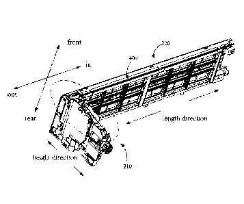
and a second electrical
wire section arranged at the filter screen rail assembly; and the first
electrical wire section is
arranged along a height direction of the cleaning assembly, and the second
electrical wire section
is arranged along a length direction of the filter screen rail assembly.
100101 In an embodiment of the present disclosure, the electrical wire
includes: a first
electrical wire section arranged at the cleaning assembly, and a second
electrical wire section
arranged at the filter screen rail assembly; and
100111 the first electrical wire section is arranged along a height
direction of the cleaning
assembly, and/or the second electrical wire section is arranged along a length
direction of the
filter screen rail assembly.
[0012] In an embodiment of the present disclosure, the electrical wire
includes: a first
electrical wire section arranged at the cleaning assembly, and a second
electrical wire section
arranged at the filter screen rail assembly; and
[0013] the first electrical wire section is arranged at an outer side and a
front side of the
cleaning assembly, the indoor unit is configured to be hung on a wall, the
front side of the
cleaning assembly is away from the wall, and the outer side of the cleaning
assembly is away
from a heat exchanger of the indoor unit.
[0014] In an embodiment of the present disclosure, a first wire clamping
member is provided
at the outer side of the cleaning assembly, and a second wire clamping member
is provided at the
front side of the cleaning assembly. The first electrical wire section passes
through the first wire
clamping member and the second wire clamping member.
[0015] In an embodiment of the present disclosure, the second wire clamping
member is
adjacent to the filter screen rail assembly, to cause the first electrical
wire section and the second
electrical wire section to bend.
[0016] In an embodiment of the present disclosure, the first wire clamping
member includes
a first through hole, and the first electrical wire section passes through the
first through hole;
and/or,
2
Date Recue/Date Received 2023-02-13
[0017] the second wire clamping member includes a second through hole, and
the first
electrical wire section passes through the second through hole.
[0018] In an embodiment of the present disclosure, a third wire clamping
member is
provided at the front side of the cleaning assembly, and the second wire
clamping member and
the third wire clamping member are arranged at an interval from top to bottom
along a height
direction of the cleaning assembly, and the first electrical wire section
further passes through the
third wire clamping member.
[0019] In an embodiment of the present disclosure, the third wire clamping
member includes
a wire routing cavity and an opening communicating with the wire routing
cavity, and a portion
of the first electrical wire section is inserted into the wire routing cavity
through the opening.
[0020] In an embodiment of the present disclosure, the electrical wire
includes: a first
electrical wire section arranged at the cleaning assembly, and a second
electrical wire section
arranged at the filter screen rail assembly.
[0021] The second electrical wire section is arranged at the front side of
the filter screen rail
assembly. The indoor unit is configured to be hung on a wall, and the front
side of the filter
screen rail assembly is away from the wall.
[0022] In an embodiment of the present disclosure, a fourth wire clamping
member is
provided at the front side of the filter screen rail assembly, and the second
electrical wire section
passes through the fourth wire clamping member.
[0023] In an embodiment of the present disclosure, the fourth wire clamping
member
includes: a wire routing wove arranged along a length direction of the filter
screen rail
assembly, and an opening communicating with the wire routing groove. At least
a portion of the
second electrical wire section is inserted into the wire routing groove
through the opening.
[0024] In an embodiment of the present disclosure, the fourth wire clamping
member
includes: first limit members, and second limit members. The number of the
first limit members
is at least two, and the two first limit members and the second limit members
are arranged
alternately at intervals. The wire routing groove and the opening connected to
the wire routing
groove are provided between each first limit member and each second limit
member and the wire
routing groove is connected to the opening, and at least a portion of the
second electrical wire
section is inserted into the wire routing groove through the opening.
3
Date Recue/Date Received 2023-02-13
[0025] In an embodiment of the present disclosure, the second limit members
are arranged
along the length direction of the filter screen rail assembly, and at least a
portion of the second
electrical wire section is supported by the second limit members.
[0026] In an embodiment of the present disclosure, the cleaning assembly is
connected to
one end of the filter screen rail assembly, and the electrical control box is
adjacent to another end
of the filter screen rail assembly; and/or,
[0027] the indoor unit further includes a face frame covering the cleaner
device, and the
cleaner device is detachable from the face frame.
[0028] The present disclosure also provides an air conditioner including an
outdoor unit and
an indoor unit including: an electric control box; a cleaner device including:
a filter screen rail
assembly; and a cleaning assembly configured to drive a filter screen to move
on the filter screen
rail assembly to clean the filter screen, and including an electrical wire
connection end; and an
electrical wire arranged at the cleaning assembly and the filter screen rail
assembly, one end of
the electrical wire being connected to the electrical wire connection end, and
another end of the
electrical wire being connected to the electric control box; wherein: the
electrical wire includes: a
first electrical wire section arranged at the cleaning assembly; and a second
electrical wire
section arranged at the filter screen rail assembly; and the first electrical
wire section is arranged
along a height direction of the cleaning assembly, and the second electrical
wire section is
arranged along a length direction of the filter screen rail assembly.
[0029] The technical solution of the present disclosure is used to arrange
the electrical wires
for connecting the cleaner device and the electric control box on the cleaning
assembly and the
filter screen rail assembly. That is, the electrical wire is arranged along
the cleaning assembly
and the filter screen rail assembly, thereby the wiring space of the chassis
of the indoor unit isn't
occupied, and the electrical wire arrangement of the cleaner device is
simplified.
BRIEF DESCRIPTION OF THE DRAWINGS
[0030] In order to more clearly describe the technical solutions in the
embodiments of the
present application or the existing technologies, the drawings used in the
description of the
embodiments or the existing technologies are briefly described below.
Obviously, the drawings
4
Date Recue/Date Received 2023-02-13
in the following description are only some embodiments of the present
disclosure. For those of
ordinary skill in the art, other drawings may be obtained according to the
structure shown in the
drawings without creative work.
[0031] FIG. 1 is a schematic diagram showing an electrical wire arranged at
a cleaner device
according to an embodiment of the present disclosure;
[0032] FIG. 2 is an enlarged view of the dotted portion in the figure;
4a
Date Recue/Date Received 2023-02-13
CA 03128268 2021-07-29
[0033] FIG. 3 is a schematic structural diagram of an electrical wire
provided at a cleaner
device in an embodiment of the present disclosure;
[0034] FIG. 4 is a schematic structural diagram of a cleaner device
according to an
embodiment of the present disclosure;
[0035] FIG. 5 is an enlarged view of a portion labeled A in FIG. 4;
[0036] FIG. 6 is an enlarged view of a portion labeled B in FIG. 4;
[0037] FIG. 7 is a schematic structural diagram showing the first
electrical wire and the
second electrical wire being fixed at the air intake grill after being
connected according to an
embodiment of the present disclosure;
[0038] FIG. 8 an enlarged view of the dotted portion in FIG. 7;
[0039] FIG. 9 is an exploded view of the first electrical wire, the
second electrical wire, and
the air intake grill in an embodiment of the present disclosure;
[0040] FIG. 10 is an exploded view of the air intake grill and the
connector according to an
embodiment of the present disclosure;
[0041] FIG. 11 an enlarged view of the dotted portion in FIG. 10.
[0042] Description of reference numerals
Table 1
Reference Reference
Name Name
Numeral Numeral
200 Cleaner device 220 Filter screen rail
assembly
Fourth wire clamping
210 Cleaning assembly 221 member
First wire clamping
211 2211 member First limit
member
2111 First through hole 2212 Second limit
member
Second wire clamping
212 member 2213 Wire routing
groove
2121 Second through hole 2214 Opening
Third wire clamping
213 member A400 Electrical wire
2131 Wire routing cavity A410 First electrical
wire section
Second electrical wire
2132 Opening A420 section
110 First electrical wire 4101 Connector limit
member
5
Date Recue/Date Received 2021-07-29
CA 03128268 2021-07-29
120 Second electrical wire 4102 Non-connector limit
member
B200 Connector 420 Second limit
member
B210 First connection terminal 421 Bearing member
B220 Second connection terminal 4211 First bearing
part
300 Air intake grill 4212 Second bearing
part
401 Receiving cavity 422 Support member
402 Opening 4221 First support
portion
410 First limit member 4222 Second support
part
411 Limit rib
[0043] The implementation, functional characteristics and advantages of
the present
disclosure will be further described with reference to the drawings in
combination with
embodiments.
DETAILED DESCRIPTION OF THE EMBODIMENTS
[0044] The technical solution in the embodiments of the present disclosure
will be described
clearly and completely with reference to the drawings in the embodiment of the
present
disclosure. It will be appreciated that the described embodiments are only
some of the
embodiment of the present disclosure, not all of the embodiments. Based on the
embodiments in
the present disclosure, other alternative embodiments may be perceived by
those of skilled in the
art that fall within the protection scope of the present disclosure.
[0045] It should be noted that all directional indicators (such as
upper, lower, left, right, front,
rear, etc.) in the embodiment of the present disclosure are only used to
explain the relative
positional relationship, movement, etc. between various components under a
certain specific
posture (as shown in the drawings). If the specific posture changes, the
directional indicator will
also change accordingly.
[0046] In the present disclosure, the terms "connected" and "fixed" etc.
should be understood
in a broad sense, unless otherwise specified and defined. For example, "fixed"
can be a fixed
connection, a detachable connection, or an forming a part integrally; it can
be a mechanical
6
Date Recue/Date Received 2021-07-29
CA 03128268 2021-07-29
connection or an electrical connection; it can be a direct connection or an
indirect connection
through an intermediate medium; and it can be the communication between
interiors of two
elements or the interaction between two elements, unless otherwise
specifically defined. For
those skilled in the art, the specific meanings of the aforementioned terms in
the present
disclosure will be appreciated according to practical conditions.
[0047] In addition, aspects of the technical solutions between the
various embodiments may
be combined with each other to form further alternative embodiments within the
protection scope
of the present disclosure.
[0048] The present disclosure relates to an air conditioner indoor unit.
[0049] In an embodiment of the present disclosure, as shown in FIG. 1 to
FIG. 3, the indoor
unit includes:
[0050] an electric control box (not shown);
[0051] a cleaner device 200 including: a cleaning assembly 210
configured to drive a filter
screen to move on the filter screen rail assembly 220 to clean the filter
screen, and including an
electrical wire connection end; and
[0052] an electrical wire A400 arranged at the cleaning assembly 210 and
the filter screen
rail assembly 220, and one end of the electrical wire A400 is connected to the
electrical wire
connection end, and another end of the electrical wire A400 is connected to
the electric control
box.
[0053] In this embodiment, it will be appreciated that the electric control
box is configured
with a circuit board therein, which is an important module for controlling the
indoor unit. The
cleaner device 200 is an assembly for driving and cleaning the filter screen.
That is, the air is
circulated in the process of operating the conditioner indoor unit circulates
air, and the air needs
to be filter screened through the filter screen after entering the indoor unit
and before passing
through the heat exchanger. After the indoor unit is used for a long time, the
filter screen
becomes dirty. The cleaning of the filter screen is achieved by the cleaner
device 200. The
process of cleaning the filter screen 200 by the cleaner device 200 is as
follows: firstly, the filter
screen is driven to run in the cleaner device 200, and the cleaning of the
filter screen is realized
in the process of operation. The specific structure of the cleaner device 200
can be referred to
other patent disclosures of the present applicant before the application date
of the present
disclosure. In order to achieve that the cleaner device 200 is controlled, it
is necessary to connect
7
Date Recue/Date Received 2021-07-29
CA 03128268 2021-07-29
the electric control box and the cleaner device 200 through the electrical
wire A400 for
transmitting electric power and/or signals.
[0054] For example, the cleaning assembly 210 is configured with a
driving structure for
driving the movement of the filter screen, a cleaning structure for cleaning
the filter screen, a
water pump, and a water cavity. The condensed water generated by the indoor
unit is pumped by
the water pump to the water cavity, and the movement of the filter screen is
driven by the driving
structure which cleaning the filter screen. The filter screen rail assembly is
configured with a
corresponding rail, and the filter screen can be moved in the rail. In
general, the electrical wire
A400 may be connected with a water pump and a drive structure of the cleaning
assembly 210,
so the electrical wire A400 is divided into two sections. The first section
A410 thereof is
configured at the cleaning assembly 210 and another section A420 thereof is
configured at the
filter screen rail assembly 220. That is, the electrical wire A400 is
configured along the cleaning
assembly 210 and the filter screen rail assembly 220 to avoid that the space
of other electrical
wires is occupied for the arrangement of the electrical wire A400 on the
chassis of the indoor
unit, and an overly messy situation with other electrical wires is avoided,
thereby the
arrangement of the electrical wire A400 connecting the cleaner device 200 is
simplified.
[0055] In an embodiment of the present disclosure, as shown in FIG. 3 to
FIG. 5, the
electrical wire A400 includes: a first electrical wire section A410 arranged
at the cleaning
assembly 210, and a second electrical wire section A420 arranged at the filter
screen rail
assembly 220; and
[0056] The first electrical wire section A410 is arranged along a height
direction of the
cleaning assembly 210, and/or the second electrical wire section A420 is
arranged along a length
direction of the filter screen rail assembly 220.
[0057] In this embodiment, in general, the cleaning assembly 210 and the
filter screen rail
assembly 220 are intersecting setting to fully utilize the internal space of
the indoor unit, so that
the first electrical wire section A410 is configured along the height
direction of the cleaning
assembly 210. The second electrical wire section A420 is configured along the
length of the filter
screen rail assembly 220, thus the length of the electrical wire A400 is
minimized.
[0058] In an embodiment of the present disclosure, as shown in FIG. 3 to
FIG. 5, the
electrical wire A400 includes:
[0059] a first electrical wire section A410 arranged at the cleaning
assembly 210, and
8
Date Recue/Date Received 2021-07-29
CA 03128268 2021-07-29
[0060] a second electrical wire section A420 arranged at the filter
screen rail assembly 220.
[0061] The first electrical wire section A410 is arranged at an outer
side and a front side of
the cleaning assembly 210. The indoor unit is configured to be hung on a wall,
and the front side
of the cleaning assembly 210 is away from the wall, and the outer side of the
cleaning assembly
210 is away from a heat exchanger of the indoor unit.
[0062] In this embodiment, in order to realize the arrangement of the
assemblies in the
cleaning assembly 210, the portion of the first electrical wire section A410
is configured on the
outer side of cleaning assembly, and the remaining portion thereof is
configured on the front side
of cleaning assembly. Thus, the setting of the assembly in the cleaning
assembly 210 is
facilitated, and the electrical wire A400 is also convenient for being
integrally arranged. The side
of the cleaning assembly 210 away from the wall is the front side thereof. The
side thereof close
to the wall is the rear side, and the side of the heat exchanger close to the
indoor unit is the inner
side, and the side of the heat exchanger away from the indoor unit is the
outer side. In addition,
the space corresponding to the front side of the cleaning assembly 210 is
relatively abundant, and
the front side space of the cleaning assembly 210 can be fully utilized.
[0063] As shown in FIG. 4 and FIG. 5, a first wire clamping member 211
is provided at the
outer side of the cleaning assembly 210, and a second wire clamping member 212
is provided at
the front side of the cleaning assembly 210. The first electrical wire section
A410 passes through
the first wire clamping member 211 and the second wire clamping member 212. In
this
embodiment, the first wire clamping member 211 is a structure for forming a
limit to the first
electrical wire section A410, and thus the various forms can be taken. For
example, a restriction
form of other electrical wires in the indoor unit is taken. For the second
wire clamping member
212, the operation is the same as the first wire clamping member 211. The
first electrical wire
section A410 is configured on the outer side and the front side of the
cleaning assembly 210 by
the arrangement of the first wire clamping member 211 and the second wire
clamping member
212.
[0064] In an embodiment, as shown in FIG. 4 and FIG. 5, the second wire
clamping member
212 is adjacent to the filter screen rail assembly 220, to cause the first
electrical wire section
A410 and the second electrical wire section A420 to bend. In this embodiment,
by such an
arrangement thereof, the first electrical wire section A410 and the second
electrical wire section
A420 are formed in a bend shape, and are corresponded to the joint of the
cleaning assembly 210
9
Date Recue/Date Received 2021-07-29
CA 03128268 2021-07-29
and the filter screen rail assembly 220, and thus, the electrical wire A400
isn't in a state of
suspension for coming off the cleaner device 200, thereby the electrical wire
A400 is prevented
from being squeezed when assembling the indoor unit.
[0065] As shown in FIG. 4 and FIG. 5, the first wire clamping member 211
includes a first
through hole 2111, and the first electrical wire section A410 passes through
the first through hole
2111; and/or,
[0066] the second wire clamping member 212 includes a second through
hole 2121, and the
first electrical wire section A410 passes through the second through hole
2121.
[0067] In this embodiment, the first wire clamping member 211 is
configured as a closed
annular structure, and is configured with a first through hole 2111, so that
the first through hole
2111 is passed through by the first electrical wire section A410. That is, the
first wire clamping
member 211 is passed through by the first electrical wire section A410. The
first electrical wire
section A410 is confined within the first through hole 2111 to prevent offset.
The same operation
is true for the second wire clamping member 212, and the details are not
repeated herein. The
first electrical wire section A410 is configured along the outer side and the
front side of the
cleaning assembly 210, and thus the first electrical wire section A410 is in a
bent state, and the
first electrical wire section A410 is prevented from detaching by the
arrangement of the first wire
clamping member 211 and the second wire clamping member 212.
[0068] Further, as shown in FIG. 4 and FIG. 5, a third wire clamping
member 213 is
provided at the front side of the cleaning assembly 210, and the second wire
clamping member
212 and the third wire clamping member 213 are arranged at an interval from
top to bottom
along a height direction of the cleaning assembly 210, and the first
electrical wire section A410
further passes through the third wire clamping member 213. In this embodiment,
the third wire
clamping member 213 is a structure for forming a limit to the first electrical
wire section A410,
and thus various forms can be employed. For example, the height direction of
the cleaning
assembly 210 is exemplified by the state in which the indoor unit is suspended
from the wall.
The cleaning assembly 210 is configured with a certain height. Thus, the first
electrical wire
section A410 located on the front side of the cleaning assembly 210 is
effectively fixed to
prevent the first electrical wire section A410 from being partially suspended
by arranging the
second wire clamping member 212 and the third wire clamping member 213 at an
interval.
[0069] As shown in FIG. 4 and FIG. 5, the third wire clamping member 213
includes a wire
Date Recue/Date Received 2021-07-29
CA 03128268 2021-07-29
routing cavity 2131 and an opening 2132 communicating with the wire routing
cavity 2131, and
a portion of the first electrical wire section A410 is inserted into the wire
routing cavity 2131
through the opening 2132. In this embodiment, the third wire clamping member
213 is not a
closed annular structure and is configured with a wire routing cavity 2131. A
portion of the first
electrical wire section A410 is inserted into the wire routing cavity 2131
through the opening
2132, such that the first electrical wire section A410 as a whole is in a
state of passing through
the third wire clamping member 213. After the first electrical wire section
A410 passes through
the first wire clamping member 211 or the second wire clamping member 212, the
portion of the
first electrical wire section A410 is inserted into the third wire clamping
member 213, thereby
the assembly efficiency of the first electrical wire section A410 is improved.
Moreover, since the
first wire clamping member 211 and the second wire clamping member 212 have a
closed
annular structure, the first electrical wire section A410 is not easily
separated from the first wire
clamping member 211 and the second wire clamping member 212. The arrangement
efficiency
of the first electrical wire section A410 is improved on the premise of
guaranteeing the fixing
effect of the electrical wire section A410.
[0070] In an embodiment of the present disclosure, as shown in FIG. 4
and FIG. 6, the
electrical wire A400 includes:
[0071] a first electrical wire section A410 arranged at the cleaning
assembly 210, and
[0072] a second electrical wire section A420 arranged at the filter
screen rail assembly 220.
[0073] The second electrical wire section A420 is arranged at the front
side of the filter
screen rail assembly 220. The indoor unit is configured to be hung on a wall,
and the front side of
the filter screen rail assembly 220 is away from the wall. In this embodiment,
as the portion of
the first electrical wire section A410 is configured on the front side of the
cleaning assembly 210,
the utilization rate of space is also improved by the arrangement of the
second electrical wire
section A420 on the front side of the filter screen rail assembly 220. Thus,
the length of the
electrical wire is minimized.
[0074] As shown in FIG. 6, a fourth wire clamping member 221 at the
front side of the filter
screen rail assembly 220, and the second electrical wire section A 420 passes
through the fourth
wire clamping member 221. The fourth wire clamping member 221 is a structure
for forming a
limit to the second electrical wire section A420, and thus various foul's can
be employed. When
the second electrical wire section A420 is passed through the fourth wire
clamping member 221,
11
Date Recue/Date Received 2021-07-29
CA 03128268 2021-07-29
the second electrical wire section A420 is confined to the fourth wire
clamping member 221,
thereby the placement of the second electrical wire section A420 in the filter
screen rail assembly
220 is achieved. With the arrangement of the first electrical wire section
A410 and the above
structure, the electrical wire A400 can be quickly configured in the cleaner
device 200.
[0075] In an embodiment of the present disclosure, as shown in FIG. 6, the
fourth wire
clamping member 221 includes: a wire routing groove 2213 arranged along a
length direction of
the filter screen rail assembly 220, and an opening 2214 communicating with
the wire routing
groove 2213. At least a portion of the second electrical wire section A420 is
inserted into the
wire routing groove 2213 through the opening 2214. In this embodiment, the
wire routing groove
2213 is a space for accommodating the second electrical wire section A420, and
the wire routing
groove 2213 is configured along the length direction of the filter screen rail
assembly 220, so
that the second electrical wire section A420 generally isn't configured with a
bend. Thus, the
second electrical wire section A420 is inserted into the wire routing groove
2213 through the
opening 2214, and the second electrical wire section A420 is in a state of
passing through the
fourth wire clamping member 221. If the length of the wire routing groove 2213
is long, the
second electrical wire section A420 may be almost completely inserted into the
wire routing
groove 2213, and the end of the second electrical wire section A420 is
connected to the electric
control box. If the length of the wire routing groove 2213 is small, a portion
of the second
electrical wire sections A420 is inserted into the wire routing groove.
[0076] As shown in FIG. 6, the fourth wire clamping member 221 includes: a
first limit
member 2211, and a second limit member 2212. The number of the first limit
members 2211 is at
least two, and the two first limit members 2211 and the second limit member
2212 are arranged
alternately at intervals. The wire routing groove 2213 and the wire routing
groove 2213
connected to the opening 2214 are provided between each first limit member
2211 and each
second limit member 2212, and the wire routing groove 2213 is connected to the
opening 2214,
and at least a portion of the second electrical wire section A420 is inserted
into the wire routing
groove 2213 through the opening 2214.
[0077] In an embodiment of the present disclosure, as shown in FIG. 6,
the second limit
members 2212 are arranged along the length direction of the filter screen rail
assembly 220, and
at least a portion of the second electrical wire section A420 is supported by
the second limit
member 2212. In this embodiment, the second electrical wire section A420 is
configured with a
12
Date Recue/Date Received 2021-07-29
CA 03128268 2021-07-29
tendency to fall downward under the action of gravity, and the second limit
member 2212 is
configured along the length direction of the filter screen rail assembly 220.
That is, the second
limit member 2212 is configured with a certain length. At least a portion of
the second electrical
wire section A420 is supported by the second limit member 2212, so that the
arrangement of the
second electrical wire section A420 is more stable.
[0078] In an embodiment of the present disclosure, as shown in FIG. 1,
the cleaning
assembly 210 is connected to one end of the filter screen rail assembly 220,
and the electrical
control box is adjacent to another end of the filter screen rail assembly 220.
In this embodiment,
the cleaning assembly 210 is located at one end of the filter screen rail
assembly 220, and the
electrical control box is adjacent to another end of the filter screen rail
assembly 220. The heat
exchanger and the air duct assembly are located between the cleaning assembly
210 and the
electrical control box. Thus, the space of the indoor unit can be fully
utilized.
[0079] The indoor unit further includes a face frame (not shown)
covering the cleaner device
200, and the cleaner device 200 is detachable from the face frame.
[0080] In this embodiment, the face frame is configured with an air inlet.
The filter screen
rail assembly 220 is located at the air inlet, and the air passes through the
air opening, that is, the
air passes through the filter screen rail assembly 220, and the air is
filtered by the filter screen
located in the filter screen rail assembly. The cleaner device is detachable
relative to the face
frame, such that the cleaner device 200 is a separate functional assembly that
the function of the
cleaner device 200 can be tested before assembling the indoor unit. Further,
since the electrical
wire A400 is configured on the cleaner device 200 (the cleaning assembly 210
and the filter
screen rail assembly 220). Thus, the arrangement of the electrical wire A400
can be realized
before the assembly of the indoor unit, and the cleaner device 200 can be
prevented from being
installed in the air conditioner. The arrangement of the electrical wire A400
is avoided to be
realized only after the cleaner device 200 being installed in the chassis of
the indoor unit. The
assembly efficiency is further improved.
100811 In other embodiments of the present disclosure, as shown in FIG.
7 to FIG. 11, the
indoor unit includes:
[0082] a first electrical wire 110 extending towards the electrical
control box, and one end of
the first electrical wire 110 is connected to the cleaning assembly, and
another end of the first
electrical wire 110 includes a first connection terminal B210;
13
Date Recue/Date Received 2021-07-29
CA 03128268 2021-07-29
[0083] a second electrical wire 120 extending towards the cleaning
assembly, and one end of
the second electrical wire 120 is connected to the electric control box, and
another end of the
second electrical wire 120 includes a second connection terminal B220; and
[0084] an air intake grill 300 arranged between the cleaning assembly
and the electrical
control box, the first connection terminal B210 is connected to the second
connection terminal
B220 to form a connector B200, and the connector B200 is fixed at the air
intake grill 300.
[0085] The air intake grill 300 is configured at the air inlet of the
indoor unit, and the filter
screen is configured on the air intake grill 300. The air is circulated in the
process of operating
the conditioner indoor unit, and the air is filtered by the filter screen when
passing through the air
intake grill 300. After the indoor unit is used for a long time, the filter
screen is easy to collect
dust or the like, so the filter screen is cleaned by setting the cleaning
assembly.
[0086] The cleaning assembly is located at one end of the air intake
grill 300. The cleaning
assembly includes a cleaning box, a cleaning structure, a driving structure,
and an electric device.
The electric device includes a motor, a water pump, a drain valve, or the
like. The cleaning box is
configured with a water cavity, and the movement of the filter screen is
driven by the driving
structure which is driven by the motor, and the cleaning structure is driven
to clean the filter
screen. The dirt on the filter screen is separated from the filter screen and
dropped into the water
cavity. The water is pumped by the water pump, and then that is mixed with the
dirt to become
the dirty water, and the drain valve is controlled to dewater the dirty water.
[0087] In order to realize the control of the cleaning assembly, the
electric device of the
cleaning assembly needs to be electrically connected to the electric control
box, so the first
electrical wire 110 is necessary to be configured. One end of the first
electrical wire 100 is
connected with the electric device of the cleaning assembly, and another end
of the first electrical
wire is configured with the first connection terminal B210. The electric
control box and the
cleaning assembly are arranged at an interval, and the electric control box is
configured at
another end of the air intake grill 300. The electric control box is
configured with a second
electrical wire 120, and the end of the second electrical wire 120 is
configured with a second
connection terminal B220. The first electrical wire 110 extends toward the
electric control box,
and the second electrical wire 120 extends toward the cleaning assembly, so
that the first
connection terminal B210 and the second connection terminal B220 are connected
to be the
connector B200, and the connector B200 are fixed at the air intake grill 300.
Since the control
14
Date Recue/Date Received 2021-07-29
CA 03128268 2021-07-29
box is used as the control center of the indoor unit, it is needed to be
electrically connected with
other assemblies. That is, the area where the control box is located is
configured with more
connection terminals. In this embodiment, the second electrical wire 120
extends toward the
cleaning assembly. That is, the second connection terminal B220 is away from
the electric
control box, and the second connection terminal B220 and the first connection
terminal B210 are
connected to be the connector B200. That is, the first connection terminal
B210 is also away
from the electric control box. Thus, the number of connection terminal of the
area where the
electric control box is located is reduced. The messy connection terminals are
avoided, thereby
the management of electrical wire is facilitated, and the electromagnetic
interference is also
reduced to some extent by reducing the number of connection terminals in the
area where the
electric control box is located.
[0088] The connector B200 is fixed at the air intake grill 300, so that
the connector B200 is
effectively fixed. However, the connector B200 is connected by the first
connection terminal
B210 and the second connection terminal B220 (for example, the electrical
connection between
the electrical wire 110 and the second electrical wire 120 is achieved by slot-
plug fit). In order to
make the first electrical wire 110, the first connection terminal B210, the
second connection
terminal B220, and the second electrical wire 120 be effectively fixed as a
whole, in an
embodiment of the present disclosure, as shown in FIG. 1 and FIG. 2, at least
a portion of the
first electrical wire 110 is fixed at the air intake grill 300, and at least a
portion of the second
electrical wire 120 is fixed at the air intake grill 300. In this embodiment,
at least a portion of the
first electrical wires 110 is fixed at the air intake grill 300, and at least
a portion of the second
electrical wires 120 is fixed at the air intake grill 300, so that the first
electrical wires 110, the
first connection terminal B210, and the second connection terminal B220 and
the second
electrical wire 120 are effectively fixed as a whole.
[0089] For example, the first electrical wire 110 includes a first
electrical wire section and a
second electrical wire section. The first electrical wire section of the first
electrical wire 110 is
taken out from the cleaning assembly, and the second electrical wire section
of the first electrical
wire 110 is fixed at the air intake grill 300. The second electrical wire 120
includes the first
electrical wire section and the second electrical wire section. The first
electrical wire section of
the second electrical wire 120 is taken out from the electric control box, and
the second electrical
wire section of the second electrical wire 120 is fixed at the electric grille
300. The second
Date Recue/Date Received 2021-07-29
CA 03128268 2021-07-29
electrical wire section of the first electrical wire 110 is configured with a
first connection
terminal B210. The second electrical wire section of the second electrical
wire 120 is configured
with the second connection terminal B220, and the first connection terminal
B210 and the
second connection terminal B220 are connected to be connector B200.
[0090] In an embodiment of the present disclosure, as shown in FIG. 7, the
connector B200
is fixed at a front side of the air intake grill 300, and at least the portion
of the first electrical wire
110 is fixed at the front side of the air intake grill 300. At least the
portion of the second
electrical wire 120 is fixed at the front side of the air intake grill 300,
and after the indoor unit is
hung on a wall, the front side of the air intake grill 300 is away from the
wall, and a rear side of
.. the air intake grill 300 is adjacent to the wall. In this embodiment, when
the indoor unit is
assembled, the rear side of the air intake grill 300 abuts against the
chassis, and the connector
B200, at least a portion of the first electrical wire 110, and at least a
portion of the second
electrical wire 120 are fixed at the front side of the air intake grill 300.
The installation work is
easily performed for workers.
[0091] In an embodiment of the present disclosure, as shown in FIG. 8 to
FIG. 11, the front
side of the air intake grill 300 includes: a plurality of first limit members
410 arranged at
intervals along a length direction of the air intake grill 300, and a
plurality of second limit
members 420, and each second limit member is arranged between each two
adjacent first limit
members 410, and a receiving cavity 401 and an opening 402 communicating with
the receiving
cavity 401 are configured by each first limit member 410 and each second limit
member 420.
The connector B200 is inserted into the receiving cavity 401 through the
opening 402, and at
least the portion of the first electrical wire 110 is inserted into the
receiving cavity 401 through
the opening 402, and at least the portion of the second electrical wire 120 is
inserted into the
receiving cavity 401 through the opening 402.
[0092] In this embodiment, as shown in FIG. 9, the receiving cavity 401
extends along the
length direction of the air intake grill 300, and the receiving cavity 401 and
the opening 402 are
the space formed by the first limit member 410 and the second limit member
420. After the
connector B200, at least a portion of the first electrical wire 110, and at
least a portion of the
second electrical wire 120 are inserted into the receiving cavity 401, the
connector B200, at least
a portion of the first electrical wire 110 and at least a portion of the
second electrical wire 120 are
limited by the first limit member 410 and the second limit member 420 to avoid
dropping of the
16
Date Recue/Date Received 2021-07-29
CA 03128268 2021-07-29
electrical wire. Since the first electrical wire 110 and the second electrical
wire 120 are integrally
long after the docking, the opening 402 is configured in the embodiment, and
the first electrical
wire 110 and the second electrical wire 120 are integrated as a whole, and can
be inserted into
the receiving cavity 401 through the opening 402. Thus, the installing work is
more convenient.
[0093] In an embodiment of the present disclosure, as shown in FIG. 8 and
FIG. 11, the first
limit member 410 extends along a thickness direction of the air intake grill
300, and the
connector B200 is arranged at an inner side of the first limit member 410
which is adjacent to the
receiving cavity 401. In this embodiment, the first limit member 410 extends
along the thickness
direction of the air intake grill 300. When the indoor unit is in the wall-
hanging state, the first
.. limit member 410 extends in the up and down directions, so that the forward
and backward
movement of the entirety after being connected by the first electrical wire
110 and the second
electrical wire 120 to the indoor unit is prevented.
[0094] In an embodiment of the present disclosure, as shown in FIG. 11,
the inner side of the
first limit member 410 is provided with at least two limit ribs 411, the at
least two limit ribs 411
are arranged at intervals along the length direction of the air intake grill
300, and the connector
B200 is arranged between the two limit ribs 411. In the embodiment, the
connector B200 is
placed between the two limit ribs 411 by configuring the limit rib 411, so
that the connector
B200 can be prevented from reciprocating along the length direction of the air
intake grill 300,
thereby the connector B200 is better limited.
[0095] In an embodiment of the present disclosure, as shown in FIG. 7 and
FIG. 8, at least
the portion of the first electrical wire 110 is supported by the second limit
member 420, and at
least the portion of the second electrical wire 120 is supported by the second
limit member. In
this embodiment, the second limit member 420 protrudes toward the front of the
air intake grill
300, and the second limit member 420 is configured to support the first
electrical wire 110 and
the second electrical wire 120. After the first electrical wire 110 and the
second electrical wire
110 being connected, which as a whole is inserted into the receiving cavity
401, and is supported
by the second limit member 420 under the action of gravity.
[0096] In an embodiment of the present disclosure, as shown in FIG. 8
and FIG. 9, one first
limit member 410 with the connector B200 at the inner side is defined as a
connector limit
member 4101, and remaining first limit members 410 are defined as non-
connector limit
members 4102.
17
Date Recue/Date Received 2021-07-29
CA 03128268 2021-07-29
[0097] One second limit member 420 adjacent to the connector limit
member 4101 is defined
as a bearing member 421, and one second limit member 420 adjacent to the non-
connector limit
members 4102 is defined as a support member 422.
[0098] The bearing member 421 includes a first bearing part 4211 in a
plate shape and
arranged horizontally, and a second bearing part 4212 fixed to the first
bearing part 4211, and at
least the portion of the first electrical wire 110 and at least the portion of
the second electrical
wire 120 are supported by the first bearing part 4211.
[0099] The support member 422 includes a first support part 4221 in a
plate shape and
arranged horizontally, and a second support part 4222 fixed to the first
support part 4221, and at
least the portion of the first electrical wire 110 and at least the portion of
the second electrical
wire 120 are supported by the first support part 4221.
[0100] In this embodiment, the connector B200 is needed to be inserted
into the inner side of
the connector limit member 4101 through the opening 402, and the bearing
member 421 is
configured adjacent to the connector limit member 4101. The bearing member 421
is configured
with the first bearing part 4211 that is in a plate shape and longitudinally
configured. The contact
area between the first bearing part 4211 and the electrical wire in the
vicinity of the connector
B200 is increased, so that the fixing of the connector B200 is more stable.
The non-connector
limit member 4102 does not need to be configured with the connector B200.
Therefore, the
support member 422 is configured which includes a first support portion 4221
and a second
support part 4222, and the first support portion 4221 is a plate shape and
longitudinally
configured. The operating space when embedding the electrical wire is
increased, and the
assembly is facilitated.
[0101] In an embodiment of the present disclosure, the indoor unit
includes a face frame (not
shown). The face frame having an air inlet, and the air intake grill 300 is
arranged at the air inlet,
and the air intake grill 300 is separable from the face frame. In this
embodiment, the air intake
grill 300 is separable relative to the face frame. Therefore, before the
indoor unit is assembled,
the air intake grill 300 and the filter screen can be separately assembled to
avoid the need to fit
the face frame to assemble the filter screen.
[0102] The present disclosure also provides an air conditioner including
an air conditioner
outdoor unit and the indoor unit of any one of the above embodiments.
[0103] The indoor unit includes:
18
Date Recue/Date Received 2021-07-29
CA 03128268 2021-07-29
[0104] a first electrical wire 110 extending towards the electrical
control box, and one end of
the first electrical wire 110 is connected to the cleaning assembly, and
another end of the first
electrical wire 110 includes a first connection terminal B210;
[0105] a second electrical wire 120 extending towards the cleaning
assembly, and one end of
the second electrical wire 120 is connected to the electric control box, and
another end of the
second electrical wire 120 includes a second connection terminal B220; and
[0106] an air intake grill 300 arranged between the cleaning assembly
and the electrical
control box, the first connection terminal B210 is connected to the second
connection teintinal
B220 to form a connector B200, and the connector B200 is fixed at the air
intake grill 300.
[0107] The air conditioner outdoor unit may be an air conditioner outdoor
unit in the prior art,
which constitutes a refrigerant circulation with the indoor unit.
[0108] The structure of the indoor unit of this embodiment can be
referred to the above
embodiments as described. Since the structure of the indoor unit of this
embodiment adopts the
technical solution of the above embodiment. At least the beneficial effects of
the technical
.. solutions of the above embodiments are obtained, and not be repeated here.
[0109] The present disclosure also provides an air conditioner including
an air conditioner
outdoor unit and the indoor unit of any one of the above embodiments.
101101 The indoor unit includes: an electric control box (not shown); a
cleaner device 200
including: a filter screen rail assembly 220; and a cleaning assembly 210
configured to drive a
filter screen to move on the filter screen rail assembly 220 to clean the
filter screen, and
including an electrical wire connection end (not shown in the figure); and an
electrical wire A400
arranged at the cleaning assembly 210 and the filter screen rail assembly 220,
and one end of the
electrical wire A400 is connected to the electrical wire connection end, and
another end of the
electrical wire A400 is connected to the electric control box.
101111 The specific structure of the indoor unit of this embodiment can be
referred to the
above embodiments as described. Since the structure of the indoor unit of this
embodiment
adopts the technical solution of the above embodiment, at least the beneficial
effects of the
technical solutions of the above embodiments are obtained, and not be repeated
here. The
refrigerant circulation is realized between the air conditioner outdoor unit
and the indoor unit.
The specific structure of the air conditioner outdoor unit can be referred to
the air conditioner
outdoor unit in the prior art, and not be repeated.
19
Date Recue/Date Received 2021-07-29
CA 03128268 2021-07-29
101121 The foregoing description merely depicts some embodiments of the
present
application and therefore is not intended to limit the scope of the
application. An equivalent
structural or flow changes made by using the content of the specification and
drawings of the
present application, or any direct or indirect applications of the disclosure
on any other related
fields shall all fall in the scope of the application.
Date Recue/Date Received 2021-07-29