Note: Descriptions are shown in the official language in which they were submitted.
FRESH AIR ASSEMBLY, AIR CONDITIONER INDOOR UNIT, AND
AIR CONDITIONER
100011
TECHNICAL FIELD
[0002] The present disclosure relates to the field of air conditioner, and
more particularly
relates to a fresh air assembly, an air conditioner indoor unit, and an air
conditioner.
BACKGROUND
[0003] A household wall-mounted air conditioner is capable of performing
heat exchange on
indoor air. If the wall-mounted air condition is operated in a confined room
for a long time, and
the indoor air is not refreshed with outdoor air during the operation, users
are prone to negative
physiological responses. The current air conditioner is typically provided
with a fresh air assembly
for air ventilation or air purification. However, due to an unstable mounting
structure of a motor
for driving a fan in the fresh air assembly, there may occur a relatively
large vibration of the fresh
air assembly and an accompanying unpleasant noise, which affects user
experience.
[0004] The description in this section merely provides background information
related to the
present disclosure and does not necessarily constitute prior art.
SUMMARY
[0005] The main objective of the present disclosure is to provide a fresh
air assembly, an air
conditioner indoor unit, and an air conditioner, aiming to decrease the
vibration of the fresh air
assembly and the accompanying noise.
[0006] In order to achieve the above objective, the present disclosure
provides a fresh air
assembly, including:
[0007] a fresh air housing including a mounting holder, a clamp space being
formed at the
mounting holder, a surface of the mounting holder away from the clamp space
being provided with
a reinforcement rib; and
1
Date Recue/Date Received 2023-02-14
[0008] a fresh air motor, mounted in the clamp space.
[0009] In the above assembly, the fresh air housing includes a main body,
the mounting holder
is disposed at a middle portion of the main body; an edge of the main body is
provided with a
protrusion edge; and the reinforcement rib is configured to extend from a
center of the mounting
holder to an edge of the fresh air housing, and connected to the protrusion
edge.
[0010] The middle portion of the main body includes an avoidance hole. The
mounting holder
includes: a frame, bending from an edge of the avoidance hole toward a center
of the avoidance
hole; and a base, fastened to the frame to enclose the clamp space. The
reinforcement rib is disposed
on surfaces of the frame and the main body away from the clamp space. The
reinforcement rib is
connected with a surface of the main body from the edge of the avoidance hole
toward the center of
the avoidance hole, and the reinforcement rib and the protrusion edge are
formed integrally.
[0011] In an embodiment of the present disclosure, the reinforcement rib is
one of a plurality of
reinforcement ribs, and the plurality of reinforcement ribs are evenly
arranged along a
circumferential direction of the frame.
[0012] In an embodiment of the present disclosure, the reinforcement rib is
sheet-shaped and
disposed perpendicular to a surface of the frame.
[0013] In an embodiment of the present disclosure, the frame includes a
plurality of spaced apart
support strips, bending from an edge of the avoidance hole toward a center of
the avoidance hole.
The reinforcement rib is one of a plurality of reinforcement ribs, two of the
plurality of
reinforcement ribs are disposed in parallel and are disposed on two sides in a
width direction of one
of the support strips.
[0014] In an embodiment of the present disclosure, each two of the
plurality of reinforcement
ribs are provided with a protrusion rib therebetween; and the protrusion rib
is configured to extend
from a center of the avoidance hole toward an edge of the avoidance hole.
[0015] In an embodiment of the present disclosure, at least one of the
plurality of reinforcement
ribs has a stair-step structure in an extension direction from a center of the
frame toward an edge of
the frame.
[0016] The present disclosure further provides an air conditioner indoor
unit. The indoor unit
includes a fresh air assembly as described in any of the above embodiments.
[0017] The present disclosure further provides an air conditioner. The air
conditioner comprises
an indoor unit including: a fresh air assembly including: a fresh air housing
including a mounting
holder, a clamp space being Rained at the mounting holder, a surface of the
mounting holder away
2
Date Recue/Date Received 2023-09-14
from the clamp space being provided with a reinforcement rib; and a fresh air
motor mounted in the
clamp space; wherein: the fresh air housing includes a main body, and an edge
of the main body is
provided with a protrusion edge; and the mounting holder is disposed at a
middle portion of the
main body, the reinforcement rib is configured to extend from a center of the
mounting holder to an
edge of the fresh air housing, and connected to the protrusion edge, and the
reinforcement rib and
the protrusion edge are formed integrally; wherein the reinforcement rib is
one of a plurality of
reinforcement ribs evenly arranged along a circumferential direction of the
frame; an extension
direction of one of the plurality of reinforcement ribs is perpendicular to an
extension direction of
the protrusion edge. The air conditioner may include an indoor unit described
in any of the above
embodiments, and an outdoor unit connected to the indoor unit.
[0018] In accordance with the fresh air assembly provided herein, the
overall structure of the
mounting holder is strengthened by arranging the reinforcement rib thereon,
and thus the mounting
holder can be prevented from a relatively large deformation caused by the
vibration of the fresh air
motor. As such, the noise generated by the fresh air assembly during operation
can be abated, which
improves the user experience. In addition, the arrangement of the
reinforcement rib can prolong the
service life of the fresh air housing, thereby ensuring a stable operation of
the fresh air motor, and
improving the performance of the fresh air assembly.
BRIEF DESCRIPTION OF THE DRAWINGS
[0019] In order to illustrate the technical solution in the embodiments of
the present disclosure
or the existing technologies more clearly, a brief description will be made
below of the drawings
referred to in the present disclosure or the existing technologies. It is
appreciated that the drawings
in the following description are merely some embodiments of the present
disclosure, and those
skilled in the art could obtain other drawings according to the structures
shown in the drawings
without any creative efforts.
[0020] FIG. 1 is a schematic structural diagram of a fresh air assembly
according to an
embodiment of the present disclosure;
[0021] FIG. 2 is a front view of the fresh air assembly in FIG. 1;
[0022] FIG. 3 is a bottom view of the fresh air assembly in FIG. 1;
[0023] FIG. 4 is a schematic structural diagram of the fresh air assembly
in FIG. 1 in another
perspective;
[0024] FIG. 5 is a schematic structural diagram of a fresh air housing of
the fresh air
3
Date Recue/Date Received 2023-09-14
CA 031.29462 2021-08-09
assembly in FIG. 1;
[0025] FIG. 6 is a schematic structural diagram of a base of the fresh air
assembly in FIG. 1.
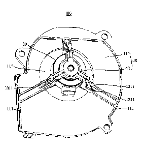
[0026] DESCRIPTION OF REFERENCE NUMERALS:
Reference numeral Name Reference numeral Name
100 fresh air assembly 1313 support strip
fresh air housing 1313a mounting hole
11 main body 1313b positioning block
111 protrusion edge 1315 protrusion rib
113 avoidance hole 133 base
13 mounting holder 1331 connection lug
13a clamp space 1333 connection hole
131 frame 1335 positioning groove
1311 reinforcement rib 30 fresh air motor
[0027] The realization of the objective, functional characteristics, and
advantages of the
present disclosure are further described with reference to the accompanying
drawings.
DETAILED DESCRIPTION OF THE EMBODIMENTS
[0028] The technical solutions of the embodiments of the present disclosure
will be
described in more detail below with reference to the accompanying drawings. It
is obvious that
the embodiments to be described are only some rather than all of the
embodiments of the present
disclosure. All other embodiments obtained by persons skilled in the art based
on the
embodiments of the present disclosure without creative efforts shall fall
within the scope of the
present disclosure.
[0029] It will be appreciated that, all directional indications (such as
up, down, left, right,
front, rear...) in the embodiments of the present disclosure are only used to
explain the relative
4
Date Recue/Date Received 2021-08-09
CA 031.29462 2021-08-09
positional relationship, motion, and the like, between components in a certain
posture. If the
particular posture changes, the directional indication changes accordingly.
[0030] In the present disclosure, unless otherwise clearly specified and
limited, the terms
"connected," "fixed," etc. should be interpreted broadly. For example, "fixed"
can be a fixed
connection, a detachable connection, or a whole; can be a mechanical
connection or an electrical
connection; can be directly connected, or indirectly connected through an
intermediate medium,
and can be the internal communication between two elements or the interaction
relationship
between two elements, unless specifically defined otherwise. For those of
ordinary skill in the art,
the specific meaning of the above-mentioned terms in the present disclosure
can be understood
according to specific circumstances.
[0031] In addition, terms such as "first" and "second" are used herein for
purposes of
description and are not intended to indicate or imply relative importance or
to imply the number
of indicated technical features. Thus, the features associated with "first"
and "second" may
comprise or imply at least one of these features. The technical solutions
between the various
embodiments can be combined with each other, but they must be based on the
realization of
those of ordinary skill in the art. When the combination of technical
solutions is contradictory or
cannot be achieved, it should be considered that such a combination of
technical solutions does
not exist, nor is it within the scope of the present disclosure.
[0032] The present disclosure provides a fresh air assembly 100.
[0033] In an embodiment of the present disclosure, as shown in FIGS. 1 to
4, the fresh air
assembly 100 includes:
[0034] a fresh air housing 10, including a mounting holder 13, where the
mounting holder 13
has a clamp space 13a; and
[0035] a fresh air motor 30, mounted in the clamp space 13a;
[0036] a surface of the mounting holder 13 away from the clamp space 13a is
provided with
a reinforcement rib 1311.
[0037] In this embodiment, the fresh air assembly 100 is typically mounted
in an air
conditioner indoor unit, and configured to vent fresh air into indoor room.
The built-in structure
of the fresh air assembly 100 is both beautiful and convenient to use. The
indoor unit herein may
be a wall-mounted type or a cabinet type, which is not limited herein. It will
be appreciated that
the fresh air assembly 100 may also be used separately.
Date Recue/Date Received 2021-08-09
CA 031.29462 2021-08-09
[0038] Specifically, the fresh air housing 10 has a fresh air cavity, and
is also provided with a
fresh air outlet and a fresh air inlet both communicated with the fresh air
cavity. In addition, a
fresh air tube is connected to the fresh air inlet, so as to communicate the
outdoor environment
and the fresh air cavity. The fresh air assembly 100 further includes a fresh
air fan for inhaling
and outputting air. The fresh air fan is mounted in the fresh air cavity, and
configured to drive the
outdoor air into the fresh air cavity, and then output the air into the indoor
room through the fresh
air outlet, so as to realize indoor air purification. The fresh air motor 30
for driving the fresh air
fan is mounted in the mounting holder 13 and connected to the fresh air fan
via a rotating shaft.
Correspondingly, the mounting holder 13 is provided with a shaft hole through
which the
rotating shaft passes. The mounting holder 13 may be integrally formed with
other parts of the
fresh air housing 10, or may be a separate structure and connected fixedly or
detachably with
other parts. The clamp space 13a is adapted to the fresh air motor 30 for a
stable mounting. The
surface of the mounting holder 13 away from the clamp space 13a is provided
with one or more
reinforcement ribs 1311. The reinforcement rib 1311 may be in a form of a
block, a strip or the
like. In addition, the reinforcement rib 1311 may be integrally formed with
the mounting holder
13, in order to effectively strengthen the overall structure of the mounting
holder 13.
[0039] In accordance with the fresh air assembly 100 herein, the overall
structure of the
mounting holder 13 is strengthened by arranging the reinforcement rib 1311
thereon, and thus the
mounting holder 13 can be prevented from a relatively large deformation caused
by the vibration
of the fresh air motor 30. As such, the noise generated by the fresh air
assembly 100 during the
operation can be abated, which improves the user experience. In addition, the
arrangement of the
reinforcement rib 1311 can prolong the service life of the fresh air housing
10, thereby ensuring a
stable operation of the fresh air motor 30, and improving the performance of
the fresh air
assembly 100.
[0040] In an embodiment, as shown in FIGS. 1, 4 and 5, the fresh air
housing 10 includes a
main body 11. The mounting holder 13 is disposed at a middle portion of the
main body 11. In
addition, a protrusion edge 111 is provided at an edge of the main body 11,
The reinforcement rib
1311 is extended from the center of the mounting holder 13 toward the edge of
the fresh air
housing 10, and connected to the protrusion edge 111.
[0041] In this embodiment, the main body 11 is constituted as a part of the
fresh air cavity. In
a specific structure, the fresh air housing 10 is a split structure, including
two detachable parts
6
Date Recue/Date Received 2021-08-09
CA 031.29462 2021-08-09
that can be fastened with each other to form the fresh air cavity, where the
main body 11 is one
of the parts. The mounting holder 13 is disposed in the middle of the main
body 11, such that the
fresh air motor 30 can be mounted in the middle of the main body 11, to
enhance the structural
stability of the fresh air motor 30. The main body 11 is generally in a form
of a volute, and
formed with a cavity for accommodating the fresh air fan. The fresh air motor
30 can be
connected to the fresh air fan correspondingly, when the two parts of the
fresh air housing 10 are
fastened to form the fresh air cavity. The surface of the main body 11 away
from the clamp space
13a, namely the surface away from the fresh air cavity, is provided with the
protrusion edge 111,
to enhance the structural strength. Specifically, the protrusion edge 111 is
sheet-shaped and
disposed perpendicular to the surface of the main body 11, which further
strengthens the stability
of the protrusion edge 111 and the main body 11. In another embodiment, the
protrusion edge
111 is arranged to extend along the edge of the main body 11 in a form of a
cylindrical strip. The
protrusion edge 111 may be distributed continuously or at intervals along the
edge of the main
body 11, as long the protrusion edge 111 is connected to an extended end of
the reinforcement rib
1311. The reinforcement rib 1311 disposed on the mounting holder 13 is
extended from the
center of the main body 11 toward the edge of the main body 11 and abutted
against the
protrusion edge 111. The reinforcement rib 1311 is also connected with the
surface of the main
body 11, and thus the reinforcement rib 1311 and the protrusion edge 111 can
be formed
integrally. The extension direction of the reinforcement rib 1311 is
perpendicular to the extension
direction of the protrusion edge 111, such that when there occur vibrations of
the fresh air motor
30, the protrusion edge 111 can effectively block the deformation of the
mounting holder 13 and
the reinforcement rib 1311 in the extension direction, which enhances the
structural stability of
the mounting holder 13. In this embodiment, the main body 11, the mounting
holder 13, the
reinforcement rib 1311 and the protrusion edge 111 are formed together as an
integral structure,
which facilitates the processing and significantly improves the strength of
the fresh air housing
10.
[0042] In
an embodiment, as shown in FIGS. 1 and 3, the middle portion of the main body
11
is provided with an avoidance hole 113. The mounting holder 13 includes a
frame 131 and a base
133. The frame 131 is configured to bend from the edge of the avoidance hole
113 toward the
center of the avoidance hole 113. The base 133 is fastened to the frame 131
and the two
cooperatively enclose to form the clamp space 13a. The reinforcement ribs 1311
are disposed on
7
Date Recue/Date Received 2021-08-09
CA 031.29462 2021-08-09
the surfaces of the frame 131 and the main body 11 away from the clamp space
13a.
[0043] In this embodiment, in order to facilitate the mounting of the fresh
air motor 30, the
mounting holder 13 includes the frame 131 and the base 133 detachably
connected with each
other. The frame 131 bends from the main body 11 toward the center of the
avoidance hole 113,
so as to form a space for accommodating the fresh air motor 30. The base 133
is fastened to the
frame 131 to form the clamp space 13a. The connection of the base 133 and the
frame 131 may
be a screw connection, a buckle connection, or a plug connection or the like.
In this embodiment,
the frame 131 and the base 133 are in a threaded connection for the purpose of
stability. Because
the frame 131 is integrally formed with the main body 11, and the fresh air
motor 30 is
accommodated in the frame 131, the reinforcement rib 1311 on the frame 131 can
improve the
structural stability of the mounting holder 13, thereby improving the overall
stability of the fresh
air assembly 100.
[0044] In an embodiment, as shown in FIG. 2, the reinforcement ribs 1311
are provided in
plurality. The plurality of reinforcement ribs 1311 are evenly arranged along
the circumferential
direction of the frame 131.
[0045] In this embodiment, the reinforcement ribs 1311 are provided in
plurality, such as two
or more than two. The plurality of reinforcement ribs 1311 can further improve
the structural
stability of the mounting holder 13. In addition, the plurality of
reinforcement ribs 1311 are
evenly arranged along the circumferential direction of the frame 131, thus the
strength of each
part of the frame 131 can be enhanced. As such, the stress concentration due
to the vibration of
the frame 131 with uneven structural strength can be prevented, thereby
improving uniformity of
the structural strength.
[0046] In an embodiment, the reinforcement rib 1311 is sheet-shaped and
disposed
perpendicular to the surface of the frame 131.
[0047] In this embodiment, the reinforcement rib 1311 is sheet-shaped, of
which the
thickness may be selected according to the thickness of the main body 11. For
example, the
thickness of the reinforcement rib 1311 is consistent with the thickness of
the main body 11. The
sheet-shaped reinforcement rib 1311 is disposed perpendicular to the surface
of the frame 131,
and according to the principle of force superposition, the deformations of the
main body 11 and
the frame 131 can be effectively reduced, to decrease the vibration frequency
of the mounting
holder 13, thereby improving the stability of the fresh air motor 30 and thus
suppressing the
8
Date Recue/Date Received 2021-08-09
CA 031.29462 2021-08-09
generation of noise.
[0048] In an embodiment, the frame 131 includes a plurality of support
strips 1313 spaced
apart. The reinforcement ribs 1311 are provided in plurality, and two of the
reinforcement ribs
1311 are disposed in parallel and respectively on two sides in a width
direction of one support
strip 131.
[0049] In this embodiment, in order to facilitate the mounting of the fresh
air motor 30 and
heat dissipation, the frame 131 has the plurality of support strips 1313
spaced apart, such that a
heat dissipation space is formed between each two of the support strips 1313,
thereby improving
the performance of the fresh air motor 30 and the heat dissipation. Each of
the support strips
1313 is configured to bend from the edge of the avoidance hole 113 to the
center of the
avoidance hole 113. The reinforcement ribs 1311 are provided in plurality, and
at least two of the
reinforcement ribs 1311 are disposed in the width direction perpendicular to
the extension
direction of the support strip 1313, in order to increase the structural
strength of the support strip
1313, thereby ensuring the mounting stability of the frame 131. Specifically,
the support strips
1313 are three, and the three support strips 1313 are evenly arranged along
the circumferential
direction of the avoidance hole 113, so as to implement the even arrangement
of the
reinforcement ribs 1311, thereby realizing material savings in case of the
guaranteed strength.
The base 133 is provided with three connection lugs 1331, and each of the
connection lugs 1331
is provided with a connection hole 1333. Correspondingly, the three support
strips 1313 are
provided with mounting holes 1313a. By this way, a screw connection can be
used between the
connection hole 1333 and the mounting hole 1313a, to realize a stable
mounting.
[0050] In addition, as shown in FIGS. 5 and 6, in order to facilitate the
mounting of the base
133 and the frame 131, the base 133 is provided with a positioning groove 1335
at an end of the
connection lug 1331, and an end of the support strip 1313 is provided with a
positioning block
1313b. The cooperation of the positioning groove 1335 with the positioning
block 1313b allows
the base 133 to be relatively fixed to the frame 131, so as to facilitate the
screw connection,
thereby improving the assembly efficiency.
[0051] In an embodiment, as shown in FIG. 4, each two of the reinforcement
ribs 1311 is
provided with a protrusion rib 1315 therebetween. The protrusion rib 1315 is
configured to
extend from the center of the frame 131 to the edge of the frame 131.
[0052] In this embodiment, in order to further enhance the structural
strength of the frame
9
Date Recue/Date Received 2021-08-09
CA 031.29462 2021-08-09
131, the protrusion rib 1315 is disposed between the two reinforcement ribs
1311 of each support
strip 1313. The protrusion rib 1315 may be integrally formed with the support
strip 1313. In
addition, the protrusion rib 1315 may be sheet-shaped and disposed
perpendicular to the surface
of the support strip 1313, of which the thickness may be smaller than the
thickness of the
reinforcement rib 1311. The protrusion rib 1315 extends from the center of the
frame 131 toward
the edge of the frame 131, and a length of the extension direction of the
protrusion rib 1315 may
be smaller than that of the reinforcement rib 1311, so as to facilitate the
processing of the
protrusion rib 1315, and further strengthen the frame 131 combined with the
reinforcement rib
1311.
[0053] In an embodiment, at least one of the reinforcement ribs 1311 has a
stair-step
structure in an extension direction from the center of the frame 131 toward
the edge of the frame
131.
[0054] In this embodiment, the support strip 1313 bends in its extension
direction, which
forms a certain stair step structure. The reinforcement rib 1311 may have a
uniform or
non-uniform height perpendicular to the support strip 1313 in its extension
direction. The
reinforcement rib 1311 may also have a stair-step structure in its extension
direction. The
stair-step structure of the reinforcement rib 1311 may match with the stair-
step structure of the
support strip 1313. Alternatively, the stair-step structure of the
reinforcement rib 1311 may be
formed at a portion in contact with the main body 11. The reinforcement rib
1311 with the
stair-step structure can further strength itself. In addition, the stair-step
structure formed in the
direction perpendicular to the extension direction can effectively block the
softness in the
extension direction and thus improve the stiffness, which strengthens the
overall structural
strength of the support strip 1313 and the frame 131, further improving the
stability of the fresh
air motor 30.
[0055] The present disclosure further provides an air conditioner indoor
unit (not shown),
including a fresh air assembly 100 as described in above embodiments. The
specific structure of
the indoor unit may refer to any of the above embodiments. It will be
appreciated that since the
indoor unit herein adopts all the technical solutions of the above
embodiments, thus can achieve
all the technical effects introduced by the above embodiments.
[0056] In this embodiment, the indoor unit is a device for performing heat
exchange on
indoor air, such as cooling or heating the air. It will be appreciated that
the indoor unit further
Date Recue/Date Received 2021-08-09
CA 031.29462 2021-08-09
includes a second housing and a main machine of the indoor unit. The second
housing includes
but is not limited to components such as a chassis and a face frame. The main
machine includes
but is not limited to an indoor heat exchanger and a wind wheel. The second
housing has an air
passage, as well as an air inlet and an air outlet. The wind wheel is disposed
in the air passage.
During the rotation of the wind wheel, the air is passing through the indoor
heat exchanger to
enter the air passage and then output through the air outlet.
100571 The fresh air assembly 100 is disposed in the second housing, and
side by side with
the main machine in the length direction of the second housing, that is, the
fresh air housing 10
of the fresh air assembly 100 is arranged side by side with the indoor heat
exchanger or the wind
wheel, so that the outdoor air circulating in the fresh air cavity does not
affect the efficiency of
indoor heat exchange. The second housing may have an opening communicated with
the fresh air
outlet of the fresh air assembly 100, so as to vent fresh air into the indoor
room. In other
embodiments, the panel of the second housing does not cover the fresh air
outlet, and the fresh
air outlet directly communicates with the indoor room, thereby effectively
improving efficiency
of refreshing the air.
100581 The present disclosure also provides an air conditioner (not shown),
including an
indoor unit and an outdoor unit connected to the indoor unit. The indoor unit
includes a second
housing, a main machine, and a fresh air assembly 100. The fresh air assembly
100 and the main
machine are arranged side by side along the length direction of the second
housing. The specific
structure of the indoor unit may refer to any of the above embodiments. It
will be appreciated
that since the indoor unit herein adopts all the technical solutions of the
above embodiments, thus
can achieve all the technical effects introduced by the above embodiments.
100591 The outdoor unit may be any outdoor unit in the related art.
100601 The foregoing description merely portrays some illustrative
embodiments in
accordance with the present disclosure and therefore is not intended to limit
the patentable scope
thereof. Any equivalent structure or flow transformations that are made taking
advantage of the
specification and accompanying drawings of the present disclosure and any
direct or indirect
applications thereof in other related technical fields shall all fall in the
scope of protection of the
present disclosure.
11
Date Recue/Date Received 2021-08-09