Note: Descriptions are shown in the official language in which they were submitted.
DETACHABLE MODULAR PROTECTIVE SHELL FOR A TRIKE
TECHNICAL FIELD
[0001] The present invention relates to trikes or Quads, more
particularly the present
invention relates to a pedal assist modular e-trike or an e-trike that
provides ergonomic
comforts of a recumbent trike, and includes a protective shell having modular
sections that
can be easily detached for ease of storage and transportation.
BACKGROUND
[0002] Three wheeled vehicles (either conventional or non-conventional)
either
human powered or electric motor powered both has been in use for years. In
human
powered vehicles, the weight/desirability to ride vehicle has always been an
issue. In recent
years, electric motor powered and pedal assisted e-trikes have gained a huge
popularity
among users due to their commercial or personal uses. Also, children, disabled
people and
senior citizens choose to ride e-trikes due to their apparent stability versus
two wheeled
vehicles. However conventional trikes lack proper stability due to which the
riders are
required to be more careful to avoid tipping trikes over. To mitigate this
risk, the three-
wheeled vehicles with a motor and driver seat centrally positioned within a
frame where the
driver sits in a recumbent and straddle position are constructed and designed.
Although such
designs provide lower centre of gravity and require less care to be taken by
the riders, the
riders can still encounter collisions against obstacles during the ride for
various reasons and
may also need to drive the trike through various environmental conditions
(such as rain,
storm, uneven terrains etc).
[0003] As a matter of fact, recumbent trikes are wonderful vehicles for
getting
outdoors leaving the cars parked. Trikes for adults and kids offer much
greater stability than
the two-wheeled bikes, and with modern technology, are much more fun, and
faster than
ever before. Recumbent trikes are ideal adaptive bikes and can be customized
to meet a
variety of special needs of the users. Conventionally, the recumbent trikes
either do not
include any external body, or include a partial or full body built on top or
around the chassis
of the trike, however the body covering the chassis are generally fixed all
around the chassis
and made completely of rigid material preferably of fiber-reinforced plastic.
The big
1
Date Recue/Date Received 2021-09-11
disadvantages of having such fixed body structure around the chassis is space
requirement
for storage of these e-trikes, and transportation or shipping costs of such
trikes as such trikes
with fixed body structure need to be transported in a fully assembled
configuration in a
custom-built crate or similar packaging. The parcel size leads to increase in
the cost of
transportation/shipping. Not only this, the end user need to spend lot of time
uncrating the
trike before he/she can use it.
[0004] Thus, what is needed is a pedal assist modular e-trike that
provides ergonomic
comforts of a recumbent trike, and a protective shell having modular sections
that can be
easily detached for ease of storage and transportation.
SUMMARY
[0005] It is an objective of the present invention to provide a pedal
assisted e-trike or
a trike in general, configured to provide an ergonomic comfort of a recumbent
trike with
added safety and portability. The safety is provided in the form of a
detachable protective
shell. The shell consists of multiple modular sections, each of which is
strategically and
ergonomically constructed to assemble or disassemble to and from the frame or
chassis of
the trike with minimal efforts.
[0006] It is another objective of the present invention to provide a
detachable modular
shell for the trike that can overcome shortcomings associated with fixed body
covering that
some of the conventional trikes do have. The detachability or modularity of
each of the
sections of the shell offers ease in storage and shipping or transportation of
the trike. The
detachability or modularity of each of the sections also allows users to
remove or not to use
the shell during summer or extreme hot weather.
[0007] According to an embodiment, each of the sections of the shell
are made of
material such as to be light weight, vibration proof, and provide great amount
of safety.
[0008] According to an embodiment, each of the sections of the shell
may be
transparent vinyl coated or coated with weather-resistant fabrics to make them
weather
proof.
2
Date Recue/Date Received 2021-09-11
[0009] According to an embodiment, each of the sections of the shell
can be
customized in size and shape depending on the trike's shape and size.
[0010] Other objects and features of the invention will become apparent
from
consideration of the following description taken in connection with the
accompanying
drawings.
BRIEF DESCRIPTION OF THE DRAWINGS
[0011] In the drawings:
[0012] FIG.1 shows a pedal assist e-trike with a detachable modular
protective shell,
according to an embodiment of the invention;
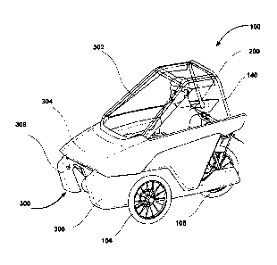
[0013] FIGS.2A-2B shows a first section and a second section of the
protective shell
that form a hood of the modular protective shell of FIG.1;
[0014] FIG.3 shows the pedal assist e-trike of the present invention
without the
protective shell;
[0015] FIG. 4 shows the pedal assist e-trike with a third section of
the protective shell
assembled to a chassis and/or frame of the e-trike;
[0016] FIG. 5 shows the hood assembled to the chassis of the e-trike
and oriented in a
raised up position to allow a user of the e-trike to enter or exit the e-
trike;
[0017] FIGS. 6A-6C shows partial sectional views of the e-trike to
demonstrate
attachment of the third section of the protective shell to the chassis of the
e-trike, according
to an exemplary embodiment of the present invention.
[0018] FIG. 7 shows a partial sectional view of the third section of
the modular
protective shell with a set of fixtures, and an air valve configured therein.
3
Date Recue/Date Received 2021-09-11
[0019] FIG.8 shows a support bracket assembly that connects frame or
chassis to the
third section of the modular protective shell, according to an exemplary
embodiment.
DETAILED DESCRIPTION
[0020] Before describing the present invention in detail, it should be
observed that the
present invention utilizes a combination of components or processes, which
constitute a
pedal assist modular e-trike with a detachable modular protective shell
configurable
thereon. Accordingly, the components or processes have been represented,
showing only
specific details that are pertinent for an understanding of the present
invention so as not to
obscure the disclosure with details that will be readily apparent to those
with ordinary skill
in the art having the benefit of the description herein. As required, detailed
embodiments of
the present invention are disclosed herein; however, it is to be understood
that the disclosed
embodiments are merely exemplary of the invention, which can be embodied in
various
forms. Therefore, specific component level details and functional details
disclosed herein
are not to be interpreted as limiting, but merely as a basis for the claims
and as a
representative basis for teaching one skilled in the art to variously employ
the present
invention in virtually any appropriately detailed structure. Further, the
terms and phrases
used herein are not intended to be limiting but rather to provide an
understandable
description of the invention. For example, the terms "a pedal assist e-trike",
"e-trike", and
"trike" all the synonymously used. As a preferred embodiment, the invention is
shown and
discussed in the form of a pedal assist e-trike, but it should be understood
that the
detachable modular shell of the present invention can be used with e-trike, or
any trikes in
general and even be customized for use with quads.
[0021] References to "one embodiment", "an embodiment", "another
embodiment",
"one example", "another example", and so on, indicate that the embodiment(s)
or
example(s) so described may include a particular feature, structure,
characteristic, property,
element, or limitation, but that not every embodiment or example necessarily
includes that
particular feature, structure, characteristic, property, element or
limitation. Furthermore,
repeated use of the phrase "in an embodiment" does not necessarily refer to
the same
embodiment. For purposes of description herein, the terms "upper," "lower,"
"right," "left,"
"rear," "front," "vertical," "horizontal," and derivatives thereof shall
relate to the invention
as oriented in FIG. 1. For the purpose of this application, the term "an
electric drive
assembly" refers to a combination of a motor and one or more battery and
associated
4
Date Recue/Date Received 2021-09-11
components. Likewise, "a pedal assist assembly" refers to a combination of one
or more
chain wheels, pedals, sprockets etc.
[0022] The pedal assist modular e-trike with a detachable modular
protective shell
will now be described with reference to the accompanying drawings,
particularly FIGS.1-8.
[0023] Referring to accompanying figures, particularly FIG.3, the
recumbent e-trike
100 according to one aspect of the present invention includes a frame or
chassis 102, a pair
of front wheels 103 and 104, and a rear wheel 105. The e-trike also includes a
seat 106
adjustably mounted to the frame 102, and supports a rider/user 200 in a
recumbent position.
Recumbent position is a semi-reclined position, with user being able to place
legs in front.
As a result, the user's body's weight is distributed over a wider area giving
more comfort.
The seat 106 is attached to the chassis 102 and is supported by one or more
variable length
bars 107 that may help in seat's adjustability or recline adjustment. The seat
106 is also
supported at the rear using a back support assembly 120 consisting of a
tubular structure as
shown in FIG.6C. These tubes may be made of known material. As seen, the back
support
assembly 120 may consist of a horizontal tube 120a, and a 11' shaped tube
120b. The
horizontal tube 120a is coupled to the ends of the 11' shaped tube 120b. The
back support
assembly 120 is clamped to the frame 102 (using a U clamp or similar kind of
clamps) and a
rear carrier 122 using another set of clamps 123 according to an embodiment.
In another
embodiment, the back support assembly 120 may be directly welded onto the
frame 102 and
the rear carrier 122.
[0024] As may be understood by those skilled in the art, the frame or
chassis 102 may
be formed using one or multiple tubes such as tube 102a that would extend
under the seat
106 to provide a rigid "backbone" for the frame 102. A chain wheel 108 and
pedals 109 of
known design may be mounted to the front of the frame 102. In an example as
shown, the
chain wheel 108 and pedals 109 are mounted on an adjustable crank 102b that's
adjustably
connected to the frame 102 (particularly slidably adjusts in length within the
tube 102a of
the frame 102). An elongated drive chain (not seen) would wrap around and
operably
engage the chain wheel 108 to drive the rear wheel 105 via a sprocket 110 (of
a known
design) located at rear of the frame 102. If gear changes are desired, for the
gear changes to
take place at the chain wheel 108 and the sprocket 110, derailleurs of a known
design may
be used at the location of chain wheel 108 and sprocket 110. The e-trike 100
would also
include brakes (not seen) operably connected to the front wheels 103 and 104.
The brakes
Date Recue/Date Received 2021-09-11
are of a known design (Eg. disc brakes), and are operated by movable brake
levers (not
seen) mounted to steering arms (not seen). In operation, the chain wheel 108,
pedals,
sprocket 110 arrangement help is steering the front wheels. The e-trike 100
will also be
operated and controlled by using one or more batteries to power a driving
motor that would
steer the front wheels 103, 104.The steering arms may be integrated with a
thumb throttle to
give an extra boost to activate the motor proportionally to the twist
regardless of pedalling
in case a user cannot pedal or need an instant acceleration or uphill push or
just need to
drive without pedalling. Optionally, the steering arms may be provided with a
display that
may provide with a variety of functions such as vehicle/mobility system
controls and
vehicle/mobility system status digitized displays to meet the trip demands. In
addition, the
display may display trip time, trip speed, trip distance, or the like. The
steering arms may be
integrated with an accelerator that can be used to accelerate the e-trike. In
an exemplary
embodiment, the e-trike may include a control system (such as a
microcontroller or
microprocessor) that may control various electronic and electrical operations
associated
with the e-trike. The microcontroller or microprocessor may be electrically
connected to one
or more batteries. A foregoing general description is provided herein with
respect to frame
structure, electric and mechanical mobility for the pedal assist e-trike. One
skilled in the art
may find some of the components and their descriptions might be missing or
concisely
presented herein and thus the same should not be construed as limiting.
[0025] As
an essence of this invention, the e-trike 100 includes a protective shell 300
having modular sections, a first section 302, a second section 304, and a
third section 306.
The third section 306 forms a pair of side walls for the e-trike 100 and
serves to protect the
rider 200 from two sides. According to an embodiment, the section 306 is made
of
inflatable material. In a preferred embodiment, the section 306 is made using
a drop-stitched
inflatable material. This material provides high strength for small amount of
weight and can
be deflated for easy storage and transportation. Each of the sections 306
present on either
side of the e-trike 100 may be a single piece unit or combination of multi
piece units joined
together using appropriate adhesive or other attachments. Each of the section
306 may be
ergonomically designed in variety of structures to securely cover the e-trike
100 from sides.
The structural configuration chosen for the section 306 would depend on the
types or design
of the trikes. Due to being inflatable in nature, each of the sections 306 may
be provided
with one or more air valves 702 (as shown in FIG.7) that may be used to fill
in air inside
the section 306 while the e-trike is in use, or eject the air out of the
section 306 during
storage or transportation of the e-trike 100.
6
Date Recue/Date Received 2021-09-11
[0026] Each of the sections 306 is attached to the frame or chassis 102
using different
mechanical or non-mechanical fixtures. In an embodiment, as shown in FIG.6A
and FIG.8,
at the front of the e-trike 100, a front support bracket assembly 800 may be
mounted onto
the crank 102b. The bracket assembly 800 includes two side arms 802 located on
two sides
of a 'T' bar 804 and a fixing plate 806 for attaching (may be bolted or welded
for example)
the bracket assembly 800 to the crank 102b of the chassis 102. A fixture, such
as fixture
704 (see FIG. 7) attached onto each of the sections 306 helps is attachment of
each of the
sections 306 to the frame 102 via the two side arms 802 of the bracket
assembly 800. The
side arms 802 include slots/holes 802a for passage of screw or bolt 704a in
order to
facilitate attachment of the section 306 to the chassis 102. Fasteners such as
nuts (not seen)
may be used to connect to the bolt, once the bolt 704a pass through the hole
802a on the
side arms 802 to mechanically attach the section 306 to the frame 102.
[0027] As seen in FIG. 6B, a clamp 602 holding onto the chassis 102 and
attached to
a bar 604 may be used for further connecting each of the section 306 to the
chassis or frame
102. In another embodiment, instead of using the clamp 602, one can directly
weld the bar
to the chassis 102. As seen, the rod 604 may connect to the section 306 using
one or more
fixtures, such as fixtures 704 using nuts as discussed above. Many different
types of fixtures
can be used as attachments and the invention should not be considered limited
to fixture 704
shown in FIG.7.
[0028] As seen in FIG. 6C, each of the sections 306 may be further
attached to the
chassis 102 at back. Particularly, suitable fixtures (Eg. straps, Velcro 610
etc.) may be used
to attach each of the sections 306 on either side of the e-trike 100 to the
the back support
assembly 120. Although the present embodiment describes three different
attachment points
for each of the section 306 to the chassis, it should be understood that one
can have even
more attachment points or lesser number of attachment points depending upon
the desired
strength of attachment between the sections 306 and the chassis 102. Although
several
mechanism or methods may be used for attachment of the sections 306 to the
chassis 102, it
is desirable the method chosen is easy for the user to self-operate in order
to be able to
assemble and disassemble the sections 306 quickly.
[0029] Referring to FIGS.1, 5 and 6C, the first section 302 of the
protective shell 300
is removably connected to the second section 304 using a tube assembly 140.
The tube
7
Date Recue/Date Received 2021-09-11
assembly 140 consists of multiple tubes (made of aluminium or other metal)
connected in a
way to support the structure of the first section 302 and to connect the first
section 302 at
front and rear of the second section 304. The first section 302 and second
section 304
provides safety to the user from upper and front side against any collisions
and weather
conditions. The section 304 includes provisions at front (not seen) and
provisions 304a at
the rear to receive the ends 140a, 140b of the tube assembly 140 and this
enables
connections between the first section 302 and the second 304 of the modular
shell 300
possible. In an embodiment, the first section 302 may preferably be made using
but not
limited to plexiglass, acrylic sheet. The first section 302 is preferably made
transparent so
the rider 200 can have clear visibility. In an embodiment, the second section
304 may
preferably be made using but not limited to a plastic, carbon fiber material.
In some other
embodiment, the first section 302 may be fixedly connected to the second
section 304. For
the purpose of this application, the first section 302 attached to the second
section 304 may
collectively be referred to as "hood" (denoted as 500 in FIG.5) of the e-trike
100. As seen
in FIG.5, the hood 500 of the e-trike 100 can be raised up to allow the rider
200 of the e-
trike 100 to enter or exit the e-trike 100. The hood 500 is attached at rear
of the e-trike 100
(particularly to the back support assembly 120) using bushings 190 at two
sides. To
elaborate and as seen in FIG. 6C, the second section 304 of the shell 300
attaches to the two
sides of the back support assembly 120 using bushings 190.The bushings 190 are
bolted
onto the U' shaped tube 120b at two sides to connect the second section 304 to
the chassis
102. These bushings 190 are greased to provide lubrication. These bushings 190
act as a
pivot point for the hood 500.
[0030] The detachable hood (the first and second sections 302,304) and
the side walls
306, and the fixtures etc. described herein above can be made in different
sizes, shapes or
structures for implementing the invention in various designs/makes of the
trikes, e-trikes or
pedal assist e-trikes, or quads.
[0031] Although the invention has been described with reference to one
or more
particular embodiments, this description is not meant to be construed in a
limiting sense.
Various modifications of the disclosed embodiments as well as alternative
embodiments of
the invention will become apparent to persons skilled in the art upon
reference to the
description of the invention. It is therefore contemplated that the appended
claims will cover
any such modifications or embodiments that fall within the scope of the
invention.
8
Date Recue/Date Received 2021-09-11