Note: Descriptions are shown in the official language in which they were submitted.
HYBRID POWER SYSTEM AND ALL-TERRAIN VEHICLE
TECHNICAL FIELD
This application relates to the field of all-terrain vehicles and, more
particularly, to a hybrid
power system and an all-terrain vehicle.
BACKGROUND
At present, all-terrain vehicles on the market are fuel-powered, most of which
adopt belt-CVT
(continuously variable transmission) systems. However, such transmission
systems have low
transmission efficiency, and heat generated raises temperature of a CVT box,
causing a belt to work
in a high temperature environment and break easily.
In addition, fuel power generally cannot enter a high-efficiency zone until
above 5000 rpm, and
the vehicle starts with low efficiency and high fuel consumption. Therefore,
improvement in
mechanical efficiency of all-terrain vehicles and transmission efficiency of
the transmission system
are research orientations in the industry. The all-terrain vehicles in the
related art are fuel-powered
and transmit power to front and rear wheels through CVT transmission systems
and front and rear
axles to realize the four-wheel drive.
Moreover, most hybrid power vehicles in the related art adopt two-wheel drive.
The advantages
of the hybrid power vehicles over conventional fuel vehicles are not obvious
due to plenty of harmful
emissions caused by parking or short-term parking and light load conditions,
and it is difficult to
arrange various components of the vehicle when trying to integrate an engine
and a motor.
SUMMARY
The present disclosure aims to solve at least one of the technical problems
existing in the related
art. To this end, the present disclosure provides a hybrid power system that
can achieve four-wheel
drive by an engine driving a first half shaft and a motor driving a second
half shaft and can solve a
problem that the front and rear drive cannot dynamically distribute driving
force.
The present disclosure also provides an all-terrain vehicle.
A hybrid power system according to embodiments of the present disclosure
includes: an engine;
a continuously variable transmission, power being transferred between the
continuously variable
transmission and the engine; a first transmission, power being transferred
between the first
Date Recue/Date Received 2021-09-14
transmission and the continuously variable transmission; a first main
decelerator, power being
transferred between the first main decelerator and the first transmission; a
first half shaft, power
being transferred between the first half shaft the first main decelerator; a
motor at least for outputting
power; a second transmission, power being transferred between the second
transmission and the
motor; a second main decelerator, power being transferred between the second
main decelerator and
the second transmission; and a second half shaft, power being transferred
between the second half
shaft and the second main decelerator, in which one of the first half shaft
and the second half shaft
is a front half shaft, and the other of the first half shaft and the second
half shaft is a rear half shaft.
For the hybrid power system according to the embodiments of the present
disclosure, the engine
drives the first half shaft and the motor drives the second half shaft, to
achieve four-wheel drive and
solve the problem that the front and rear drive cannot dynamically distribute
the driving force.
According to some embodiments of the present disclosure, the continuously
variable
transmission and the first transmission are arranged on the engine, and a
first transmission shaft is
coupled between the first transmission and the first main decelerator.
According to some embodiments of the present disclosure, the continuously
variable
transmission and the first transmission are arranged on both axial sides of
the engine.
According to some embodiments of the present disclosure, the first
transmission has a first
transmission output end, the first main decelerator has a first main
decelerator input end, and the
first transmission output end is transmissively coupled to the first main
decelerator input end.
According to some embodiments of the present disclosure, the engine and the
first transmission
are arranged on a same side of the continuously variable transmission, and the
first transmission is
fixed on a side of the engine adjacent to the first half shaft.
According to some embodiments of the present disclosure, the first
transmission includes a
shell and a first transmission assembly; the first main decelerator includes a
first main deceleration
assembly; and the first transmission assembly and the first main deceleration
assembly are arranged
in the shell.
According to some embodiments of the present disclosure, the second
transmission is fixed
between the motor and the second main decelerator.
According to some embodiments of the present disclosure, the second
transmission includes a
first shaft, a second shaft, a third shaft, a first reduction gear set and a
second reduction gear set; the
first reduction gear set includes a first gear arranged on the first shaft and
a second gear arranged on
2
Date Recue/Date Received 2021-09-14
the second shaft and meshing with the first gear; the second reduction gear
set includes a third gear
arranged on the second shaft and a fourth gear arranged on the third shaft and
meshing with the third
gear; power is transferred between the first shaft and the motor, and power is
transferred between
the third shaft and the second main decelerator.
According to some embodiments of the present disclosure, the second
transmission includes a
planetary gear mechanism, and the planetary gear mechanism includes a sun
gear, a planetary carrier,
a gear ring, and a planetary gear arranged on the planetary carrier and
meshing between the sun gear
and the gear ring; power is transferred between the sun gear and the motor,
one of the planetary
carrier and the gear ring is fixed, and power is transferred between the other
of the planetary carrier
and the gear ring and the second main decelerator.
According to some embodiments of the present disclosure, the second
transmission is a
decelerator with parallel shafts and internal meshing, and includes a driving
gear and a driven gear;
the driven gear includes a gear ring, and the driving gear meshes in the gear
ring; power is transferred
between the driving gear and the motor, and power is transferred between the
driven gear and the
second main decelerator.
According to some embodiments of the present disclosure, the motor is one of
an electric motor
and an electric generator.
According to some embodiments of the present disclosure, the hybrid power
system further
includes a controller and a vehicle speed sensor electrically coupled to the
controller; the controller
controls the engine to start after the motor starts and a vehicle speed
detected by the vehicle speed
sensor reaches a predetermined value.
A hybrid power system according to the present disclosure includes: an engine;
a continuously
variable transmission fixed on a first axial side of the engine, power being
transferred between the
continuously variable transmission and the engine; a first transmission fixed
on a second axial side
of the engine, power being transferred between the first transmission and the
continuously variable
transmission; a first transmission shaft, power being transferred between a
first end of the first
transmission shaft and the first transmission; a first main decelerator, power
being transferred
between the first main decelerator and a second end of the first transmission
shaft; a first half shaft,
power being transferred between the first half shaft and the first main
decelerator; a motor at least
for outputting power; a second transmission, power being transferred between
the second
transmission and the motor; a second main decelerator, power being transferred
between the second
3
Date Recue/Date Received 2021-09-14
main decelerator and the second transmission, and the second transmission
being fixed between the
motor and the second main decelerator; a second half shaft, power being
transferred between the
second half shaft and the second main decelerator, in which one of the first
half shaft and the second
half shaft is a front half shaft, and the other of the first half shaft and
the second half shaft is a rear
half shaft.
A hybrid power system according to the present disclosure includes: an engine;
a continuously
variable transmission fixed on an axial side of the engine, power being
transferred between the
continuously variable transmission and the engine; a first transmission, power
being transferred
between the first transmission and the continuously variable transmission; a
first main decelerator,
power being transferred between the first main decelerator and the first
transmission, and the first
transmission being fixed between the engine and the first main decelerator; a
first half shaft, power
being transferred between the first half shaft and the first main decelerator;
a motor at least for
outputting power; a second transmission, power being transferred between the
second transmission
and the motor; a second main decelerator, power being transferred between the
second main
decelerator and the second transmission, and the second transmission being
fixed between the motor
and the second main decelerator; a second half shaft, power being transferred
between the second
half shaft and the second main decelerator, in which one of the first half
shaft and the second half
shaft is a front half shaft, and the other of the first half shaft and the
second half shaft is a rear half
shaft.
An all-terrain vehicle according to embodiments of the present disclosure
includes the above
hybrid power system.
Additional aspects and advantages of embodiments of present disclosure will be
given in part
in the following descriptions, become apparent in part from the following
descriptions, or be learned
from the practice of the embodiments of the present disclosure.
BRIEF DESCRIPTION OF THE DRAWINGS
These and/or other aspects and advantages of the present disclosure will
become apparent and
readily appreciated from the following descriptions to the embodiments with
reference to the
drawings, in which:
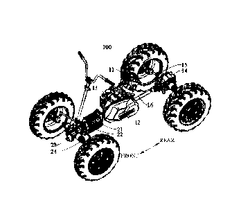
FIG. I is a schematic view of an all-terrain vehicle according to an
embodiment of the present
disclosure;
4
Date Recue/Date Received 2021-09-14
FIG. 2 is a schematic view of a hybrid power system according to some
embodiments of the
present disclosure;
FIG. 3 is a schematic view of a hybrid power system according to other
embodiments of the
present disclosure;
FIG. 4 is a schematic view of a second transmission according to some
embodiments of the
present disclosure;
FIG. 5 is a schematic view of a second transmission according to other
embodiments of the
present disclosure;
FIG. 6 is a schematic view of a second transmission according to still other
embodiments of
the present disclosure;
FIG. 7 is a schematic view of a controller and a vehicle speed sensor
according to an
embodiment of the present disclosure;
FIG. 8 is a schematic view of a first transmission and a first main
decelerator according to an
embodiment of the present disclosure.
Reference numerals:
S: all-terrain vehicle;
100: hybrid power system;
11: engine; 12: continuously variable transmission; 13: first transmission;
131: shell; first
transmission assembly 132; 14: first main decelerator; 141: first main
deceleration assembly; 15:
first half shaft; 16: first transmission shaft;
21: motor; 22: second transmission; 23: second main decelerator; 24: second
half shaft;
31: first shaft; 32: second shaft; 33: third shaft; 34: first reduction gear
set; 341: first gear; 342:
second gear; 35: second reduction gear set; 351: third gear; 352: fourth gear;
41: planetary gear mechanism; 42: sun gear; 43: planetary gear; 44: planetary
carrier; 45: gear
ring;
51: driving gear; 52: driven gear; 62: first half shell; 63: second half
shell;
70: controller; 80: vehicle speed sensor;
200: wheel; 300: frame.
DETAILED DESCRIPTION
Embodiments of the present disclosure will be described in detail below, and
the embodiments
Date Recue/Date Received 2021-09-14
described with reference to the drawings are exemplary. The embodiments of the
present disclosure
will be illustrated below.
A hybrid power system 100 according to embodiments of the present disclosure
will be
described below with reference to FIGS. 1 to 6. The present disclosure also
proposes an all-terrain
vehicle having the hybrid power system 100.
As illustrated in FIG. 2 and FIG. 3, the hybrid power system 100 includes an
engine 11, a
continuously variable transmission 12, a first transmission 13, a first main
decelerator 14, and a first
half shaft 15. Power is transferred between the continuously variable
transmission 12 and the engine
11; power is transferred between the first transmission 13 and the
continuously variable transmission
12; power is transferred between the first main decelerator 14 and the first
transmission 13; and
power is transferred between the first half shaft 15 and the first main
decelerator 14. The engine 11
serves as a main power source of the vehicle, and when the vehicle is in a
fuel-powered high-
efficiency zone, the engine 11 may start running. The engine 11 first
transfers power to the
continuously variable transmission 12, and in turn the continuously variable
transmission 12
transfers the power by using a transmission belt in cooperation with driving
and driven wheels of
variable working diameters, to achieve a continuous change in a transmission
ratio between the
engine 11 and the continuously variable transmission 12, thereby obtaining the
best cooperation
between the continuously variable transmission 12 and working conditions of
the engine 11.
In addition, power is transferred between the first transmission 13 and the
continuously variable
transmission 12, and power is transferred between the first main decelerator
14 and the first
transmission 13. The first transmission 13 is a mechanism for changing speed
and torque from the
engine 11. The first transmission 13 may change a transmission ratio between
an output shaft and
an input shaft in a fixed or stepped manner. The first main decelerator 14 may
also change the torque
and speed in the hybrid power system 100, increasing a torque from the first
transmission 13 while
reducing speed and changing a transmission direction of the torque. In
addition, the power from the
first main decelerator 14 is transmitted to the first half shaft 15.
As illustrated in FIGS. 2 and 3, the hybrid power system 100 further includes:
a motor 21 at
least for outputting power, a second transmission 22, a second main
decelerator 23, and a second
half shaft 24. Power is transferred between the second transmission 22 and the
motor 21; power is
transferred between the second main decelerator 23 and the second transmission
22; and power is
transferred between the second half shaft 24 and the second main decelerator
23. The motor 21 is
6
Date Recue/Date Received 2021-09-14
able to convert electric energy into kinetic energy. The motor 21 is started
when the vehicle starts,
and the motor 21 works before the engine 11 of the vehicle works in the fuel-
powered high-
efficiency zone. By taking advantage of low-speed and high-torque
characteristics and high
mechanical efficiency of the motor 21, the motor 21 is independently used to
drive the first half shaft
15, such that power distribution of the vehicle becomes more reasonable during
driving.
One of the first half shaft 15 and the second half shaft 24 is a front half
shaft and the other
thereof is a rear half shaft. That is, the motor 21 may be used as a driving
force source of the front
half shaft, and the engine 11 may be used as a driving force source of the
rear half shaft. Alternatively,
the engine 11 may be used as the driving force source of the front half shaft,
and the motor 21 may
be used as the driving force source of the rear half shaft. With this
arrangement, the front half shaft
and the rear half shaft are independently driven by the motor 21 and the
engine 11, such that the
vehicle may achieve four-wheel drive, and the front half shaft and the rear
half shaft may
dynamically distribute the driving force to improve the reasonable power
distribution of the vehicle
when driving.
Thus, the engine 11 drives the first half shaft 15 and the motor 21 drives the
second half shaft
24, thereby achieving the four-wheel drive and dynamic distribution of the
driving force. On this
basis, the hybrid power system 100 with such arrangement may drive the first
half shaft 15 through
the motor 21 when the vehicle starts, and enjoy the high mechanical efficiency
by using the low-
speed and high-torque characteristics of the motor 21. The engine 11 is used
to provide the driving
force to the vehicle after the vehicle reaches a certain speed. At this time,
the engine 11 works in the
fuel-powered high-efficiency zone, and hence the vehicle works in the high-
efficiency zone, thereby
achieving energy conservation and emission reduction.
According to an embodiment of the present disclosure, as illustrated in FIG.
2, the continuously
variable transmission 12 and the first transmission 13 are both arranged on
the engine 11, and a first
transmission shaft 16 is coupled between the first transmission 13 and the
first main decelerator 14.
Specifically, the first transmission shaft 16 is coupled between the first
transmission 13 and the first
main decelerator 14, and the first transmission shaft 16, together with the
first transmission 13 and
the first main decelerator 14, transmits the power of the engine 11 to wheels
200, to generate the
driving force for the vehicle. Moreover, the continuously variable
transmission 12, the first
transmission 13 and the engine 11 are positioned close to a middle part of the
vehicle, such that the
center of gravity of the vehicle is close to a middle position, and thus the
vehicle is more stable when
7
Date Recue/Date Received 2021-09-14
driving.
As illustrated in FIG. 2, the continuously variable transmission 12 and the
first transmission 13
are arranged on both axial sides of the engine 11. With this arrangement,
space among the
continuously variable transmission 12, the first transmission 13 and the
engine 11 may be reasonably
utilized, and the engine 11, the continuously variable transmission 12 and the
first transmission 13
may form an overall power structure, to improve compactness of the hybrid
power system 100. In
addition, the continuously variable transmission 12 and the first transmission
13 with such
arrangement may also balance load on both sides of the engine 11 and improve
the stability of the
vehicle.
According to another embodiment of the present disclosure, as illustrated in
FIG. 3, the first
transmission 13 has a first transmission output end, the first main
decelerator 14 has a first main
decelerator input end, the first transmission output end is coupled to the
first main decelerator input
end, and power is transferred between the first transmission output end and
the first main decelerator
input end. With such arrangement, the first transmission shaft 16 between the
first main decelerator
14 and the first transmission 13 may be omitted, and instead, the first
transmission 13 and the first
main decelerator 14 may be directly coupled, which can facilitate the assembly
of the vehicle and
reduce the cost. In addition, with such arrangement, the engine 11, the
continuously variable
transmission 12 and the first transmission 13 as a whole may move backward,
and a part of a middle
area is vacant, which can facilitate the assembly of other components.
As illustrated in FIG. 3, the engine 11 and the first transmission 13 are
arranged on a same side
of the continuously variable transmission 12, and the first transmission 13 is
fixed on a side of the
engine 11 adjacent to the first half shaft 15. With this arrangement, the
space among the continuously
variable transmission 12, the first transmission 13 and the engine 11 may be
reasonably utilized.
That is, the engine 11 and the first transmission 13 may be fixedly coupled in
a front-rear direction.
The first transmission 13 with such arrangement can realize direct power
transmission with the first
main decelerator 14 at a rear side of the engine 11, which may improve the
integration among the
engine 11, the continuously variable transmission 12, the first transmission
13 and the first main
decelerator 14.
As illustrated in FIG. 8, the first transmission 13 includes a shell 131 and a
first transmission
assembly 132; the first main decelerator 14 includes a first main deceleration
assembly 141; and the
first transmission assembly 132 and the first main deceleration assembly 141
are both arranged in
8
Date Recue/Date Received 2023-03-28
the shell 131. The first transmission assembly 132 and the first main
deceleration assembly 141
share the shell 131, which can facilitate the arrangement of the first
transmission 13 and the first
main decelerator 14, save space, and further improve the integration of the
hybrid power system 100.
According to some embodiments of the present disclosure, as illustrated in
FIGS. 4 to 6, the
second transmission 22 is fixed between the motor 21 and the second main
decelerator 23. With this
arrangement, the internal space of the vehicle can be reasonably utilized, and
the compactness
among the second transmission 22, the motor 21 and the second main decelerator
23 can be improved.
The power generated by the motor 21 is transmitted to the second half shaft 24
through the second
transmission 22 and the second main decelerator 23 successively, to drive the
vehicle to move.
According to an embodiment of the present disclosure, as illustrated in FIG.
4, the second
transmission 22 includes a first shaft 31, a second shaft 32, a third shaft
33, a first reduction gear set
34 and a second reduction gear set 35. Power is transferred between the first
shaft 31 and the motor
21. The first reduction gear set 34 is arranged between the first shaft 31 and
the second shaft 32, and
the second reduction gear set 35 is arranged between the second shaft 32 and
the third shaft 33.
Power is transferred between the third shaft 33 and the second main
decelerator 23. By arranging
the first reduction gear set 34 between the first shaft 31 and the second
shaft 32 and arranging the
second reduction gear set 35 between the second shaft 32 and the third shaft
33, the first reduction
gear set 34 and the second reduction gear set 35 can achieve speed reduction
between the motor 21
and the second main decelerator 23. The second transmission 22 is a two-stage
decelerator.
Furthermore, the first reduction gear set 34 includes a first gear 341 and a
second gear 342
meshing with each other; the second reduction gear set 35 includes a third
gear 351 and a fourth
gear 352 meshing with each other. The first gear 341 is arranged on the first
shaft 31; the second
gear 342 and the third gear 351 are arranged on the second shaft 32; and the
fourth gear 352 is
arranged on the third shaft 33. The first gear 341 and the second gear 342 are
in meshing transmission,
such that power of the first shaft 31 can be transmitted to the second shaft
32. The second gear 342
and the third gear 351 share the second shaft 32, such that the power can be
transmitted to the second
gear 342. The third gear 351 and the fourth gear 352 are in meshing
transmission, such that the
power can be transmitted to the fourth gear 352, i.e., the third shaft 33.
Power is transferred between
the first shaft 31 and the motor 21, and power is transferred between the
third shaft 33 and the second
main decelerator 23, such that the power of the motor 21 can be transmitted to
the second main
decelerator 23.
9
Date Recue/Date Received 2021-09-14
According to another embodiment of the present disclosure, as illustrated in
FIG. 5, the second
transmission 22 includes a planetary gear mechanism 41, and the planetary gear
mechanism 41
includes a sun gear 42, a planetary gear 43, a planetary carrier 44 and a gear
ring 45. The planetary
gear 43 is arranged on the planetary carrier 44 and meshes between the sun
gear 42 and the gear ring
45, and power is transferred between the sun gear 42 and the motor 21. One of
the planetary carrier
44 and the gear ring 45 is fixed, and the other thereof realizes power
transmission with the second
main decelerator 23. The motor 21 drives the sun gear 42 to bring the
planetary gear 43 into rotation.
When the gear ring 45 is fixed with the second main decelerator 23, power is
transferred between
the planetary carrier 44 and the second main decelerator 23. When the
planetary carrier 44 is fixed
with the second main decelerator 23, power is transferred between the gear
ring 45 and the second
main decelerator 23. The planetary gear mechanism 41 has characteristics of
light weight, small
volume, large transmission ratio range, high efficiency, stable operation and
low noise.
According to another embodiment of the present disclosure, as illustrated in
FIG. 6, the second
transmission 22 is a decelerator with parallel shafts and internal meshing,
and includes a driving
gear 51 and a driven gear 52. Power is transferred between the driving gear 51
and the motor 21.
The driven gear 52 includes a gear ring, the driving gear 51 meshes in the
gear ring, and power is
transferred between the driven gear 52 and the second main decelerator 23. By
using the internal
meshing transmission between the driving gear 51 and the driven gear 52, speed
reduction can be
achieved, and the space in the second transmission 22 can be saved.
As illustrated in FIGS. 4-6, a first half shell 62 is arranged on a side of
the motor 21 facing the
second main decelerator 23, and a second half shell 63 is arranged on a side
of the second main
decelerator 23 facing the motor 21. The first half shell 62 and the second
half shell 63 are arranged
opposite to each other and form a shell of the second transmission 22. That
is, the first half shell 62
is fixedly coupled to the motor 21, the second half shell 63 is coupled to the
second transmission 22,
and the first half shell 62 and the second half shell 63 are arranged
oppositely and form the shell of
the second transmission 22. In this way, the shell of the second transmission
22 can be formed
conveniently without additionally providing a shell of the second transmission
22. According to
some embodiments of the present disclosure, the first half shell 62 may be
integrally formed with a
shell of the motor 21, the second half shell 63 may be integrally formed with
a shell of the second
main decelerator 23, and such an arrangement can improve structural strength
of the shell of the
second transmission 22.
Date Recue/Date Received 2021-09-14
According to some embodiments of the present disclosure, the motor 21 may be
one of an
electric motor and an electric generator 21. When the motor 21 is an electric
motor, the electric
motor only functions as a power output source, and power is transferred
between the electric motor
and the second transmission 22 and is transferred to the second half shaft 24
through the second
main decelerator 23. When the motor 21 is an electric generator, the electric
generator may function
not only as a power source, but also as a generator. When the vehicle starts,
the electric generator
converts electric energy into kinetic energy; when the vehicle runs stably,
the electric generator
converts kinetic energy into electric energy, that is, the vehicle may be
charged, and the electric
energy can be supplied to the vehicle.
In addition, the hybrid power system 100 further includes a controller 70 and
a vehicle speed
sensor 80 electrically coupled to the controller 70. The controller 70
controls the engine 11 to start,
after the motor 21 starts and a vehicle speed detected by the vehicle speed
sensor 80 reaches a
predetermined value. Through the arrangement of the controller 70 and the
vehicle speed sensor 80,
the motor 21 functions as the power source when the vehicle starts; after a
certain vehicle speed is
reached, the controller 70 controls the engine 11 to start, and the engine 11
works in the high-
efficiency zone, to allow the vehicle to work in the high-efficiency zone of
the engine 11, thereby
achieving energy conservation and emission reduction.
Specific structures of two kinds of hybrid power systems 100 will be described
below with
reference to FIGS. 2 and 3.
As illustrated in FIG. 2, the hybrid power system 100 according to an
embodiment of the
present disclosure may include: an engine 11, a continuously variable
transmission 12, a first
transmission 13, a first main decelerator 14, a first half shaft 15, a first
transmission shaft 16, a motor
21, a second transmission 22, a second main decelerator 23 and a second half
shaft 24. Power is
transferred between the continuously variable transmission 12 and the engine
11, and the
continuously variable transmission 12 is fixed on one axial side of the engine
11. Power is transferred
between the first transmission 13 and the continuously variable transmission
12, and the first
transmission 13 is fixed on the other axial side of the engine 11. Power is
transferred between one
end of the first transmission shaft 16 and the first transmission 13; power is
transferred between the
first main decelerator 14 and the other end of the first transmission shaft
16; and power is transferred
between the first half shaft 15 and the first main decelerator 14. Power is
transferred between the
second transmission 22 and the motor 21; power is transferred between the
second main decelerator
11
Date Recue/Date Received 2021-09-14
23 and the second transmission 22, and the second transmission 22 is fixed
between the motor 21
and the second main decelerator 23; power is transferred between the second
half shaft 24 and the
second main decelerator 23. The first half shaft 15 is a rear half shaft and
the second half shaft 24 is
a front half shaft; or the first half shaft 15 is a front half shaft and the
second half shaft 24 is a rear
half shaft.
As illustrated in FIG. 3, the hybrid power system 100 according to an
embodiment of the
present disclosure may include: an engine 11, a continuously variable
transmission 12, a first
transmission 13, a first main decelerator 14, a first half shaft 15, a motor
21, a second transmission
22, a second main decelerator 23 and a second half shaft 24. Power is
transferred between the
continuously variable transmission 12 and the engine 11, and the continuously
variable transmission
12 is fixed on one axial side of the engine 11. Power is transferred between
the first transmission 13
and the continuously variable transmission 12, and power is transferred
between the first main
decelerator 14 and the first transmission 13, which is direction transmission.
That is, an output end
of the first transmission 13 directly transmits power to an input end of the
first main decelerator 14,
without additionally arranging any transmission shaft. The first transmission
13 is fixed between the
engine 11 and the first main decelerator 14. Power is transferred between the
first half shaft 15 and
the first main decelerator 14; power is transferred between the second
transmission 22 and the motor
21; power is transferred between the second main decelerator 23 and the second
transmission 22;
the second transmission 22 is fixed between the motor 21 and the second main
decelerator 23; and
power is transferred between the second half shaft 24 and the second main
decelerator 23. The first
half shaft 15 is a rear half shaft and the second half shaft 24 is a front
half shaft; or the first half shaft
15 is a front half shaft and the second half shaft 24 is a rear half shaft.
An all-terrain vehicle S according to embodiments of a second aspect of the
present disclosure
includes the hybrid power system 100 of the above embodiments, a frame 300,
and wheels 200. The
hybrid power system 100 is mounted to the frame 300, and the wheels 200 may be
mounted at shaft
ends of the first half shaft 15 and the second half shaft 24, correspondingly.
The wheels 200 include
front wheels and rear wheels.
An operation mode of the all-terrain vehicle S will be described below.
In an independent operation mode of the motor 21, the motor 21 drives the all-
terrain vehicle
S independently without the help of the engine 11. The motor 21 drives the
front wheels of the all-
terrain vehicle S through the second transmission 22, the second main
decelerator 23 and the second
12
Date Recue/Date Received 2021-09-14
half shaft 24. In addition, the motor 21 is used for driving at low speed,
which reduces fuel
consumption and is suitable for travelling in the city.
In a hybrid power operation mode that is the most commonly used operation mode
for all-
terrain vehicle S, fuel consumption and emission can be reduced through
reasonable power
distribution. The all-terrain vehicle S moves to a certain speed under the
drive of the motor 21, and
the engine 11 starts and works in the high-efficiency zone, thereby reducing
the fuel consumption
of the all-terrain vehicle S. The engine 11 drives the rear wheels of the all-
terrain vehicle S through
the continuously variable transmission 12, the first transmission 13, the
first main decelerator 14 and
the first half shaft 15, and the motor 21 drives the front wheels of the all-
terrain vehicle S through
the second transmission 22, the second main decelerator 23 and the second half
shaft 24.
In a braking control operation mode: more braking energy can be recovered by
optimizing the
relationship between a braking torque of the motor 21 and a brake. The front
wheels provide an
electricity-generating torque to the motor 21 through the second half shaft
24, the second main
decelerator 23 and the second transmission 22. The motor 21 is converted into
the electric generator
21 to generate electricity and charge a battery assembly, thereby achieving a
purpose of energy
capture during braking. When forced braking is performed, the controller
receives a signal from a
brake pedal sensor and increases the electricity-generating torque of the
motor 21 by adjusting the
controller of the motor 21.
In the descriptions of the embodiments of the present application, it is to be
understood that,
terms such as "central," "longitudinal," "lateral," "length," "width,"
"thickness," "upper," "lower,"
"front," "rear," "left," "right," "vertical," "horizontal," "top," "bottom,"
"inner," "outer,"
"clockwise," "counterclockwise," "axial," "radial," "circumferential" or the
like indicate the
orientation or positional relationship based on the orientation or positional
relationship illustrated in
the drawings. These terms are merely for convenience and simplification of
description, rather than
indicate or imply that referred device or element must have a specific
orientation, or be constructed
and operated in a specific orientation, and therefore cannot be understood as
limitation on the present
disclosure.
Reference throughout this specification to terms "one embodiment," "some
embodiments," "an
exemplary embodiment," "an example," "a specific example," or "some examples,"
means that a
particular feature, structure, material, or characteristic described in
connection with the embodiment
or example can be included in at least one embodiment or example of the
present disclosure. In this
13
Date Recue/Date Received 2021-09-14
specification, the above terms are not necessarily referring to the same
embodiment or example.
Although embodiments of the present disclosure have been illustrated and
described above, it
should be understood by those skilled in the art that changes, modifications,
alternatives, and
variations may be made in the embodiments without departing from principles
and purposes of the
present disclosure. The scope of this disclosure is limited by the claims and
their equivalents.
14
Date Recue/Date Received 2021-09-14