Note: Descriptions are shown in the official language in which they were submitted.
INNER CIRCULATION HEAT-DISSIPATING LED LAMP CAP
FIELD OF THE INVENTION
[0001] The invention relates to the field of automobile headlights, in
particular to an inner
circulation heat-dissipating LED lamp cap.
BACKGROUND OF THE RELATED ART
[0002] With its energy-saving and luminous characteristics, LED lamps
gradually began to
replace many light source structures in the past. As automobile lights, LED
lights are gradually
replacing incandescent lights and other light sources. The heat dissipation of
LED lights for
automobile lights is a big problem. Many LED automobile lights have poor heat
dissipation
effects, resulting in an increase in temperature that affects the stability
and service life of the
entire structure. At the same time, because most of the LED automobile lights
on the market
use ordinary convection fans (the working principle is: the lamp bead
generates heat when it is
working, and it is conducted to the aluminum radiator at the bottom by copper
or aluminum
parts, and then blows air against the radiator through a fan to achieve the
purpose of heat
dissipation), ordinary convection cooling fans are susceptible to working
environment and time,
which will produce dust and dirt, thereby reducing the working life of the
cooling fan and the
service life of the entire lamp.
SUMMARY OF THE INVENTION
[0003] The technical problem to be solved by the invention is to provide an
inner circulation
heat-dissipating LED lamp cap. The invention uses an inner circulation heat-
dissipating method
in a sealed automobile lamp component, and uses the internal air in the
automobile lamp
component to circulate heat, which can not only prevent the life of the
cooling fan from being
affected by the external environment during work, but also achieve the snow
melting function
when used in cold areas in winter, thereby improving driving safety in rain
and snow.
[0004] The invention is realized by the following technical solutions: an
inner circulation heat-
dissipating LED lamp cap, comprising a shell, a control circuit, and a power
supply circuit,
wherein one side of the shell is connected with a light-emitting component;
the outside of the
1
Date Recue/Date Received 2021-09-17
shell is installed with a metal holder; the inside of the shell is provided
with a heat-dissipating
component; the output end of the heat-dissipating component directly faces the
light-emitting
component; the high-pressure airflow generated by the heat-dissipating
component is blown to
the light-emitting component to take away the heat, and then an inner
circulation warming
airflow is formed inside.
[0005] Preferably, the light-emitting component comprises a red copper lamp
post; a flat
mounting surface is respectively formed on the upper and lower surfaces of the
red copper lamp
post; a hollow cavity is formed inside the red copper lamp post; a copper
substrate is
respectively installed on the upper and lower surfaces of the red copper lamp
post; one end of
the copper substrates respectively extends into the hollow cavity of the red
copper lamp post;
the copper substrate is installed with LED chips.
[0006] Preferably, a thermal conductive sheet is provided between the bottom
of the copper
substrate and the red copper lamp post; the heat on the LED chip is
transferred to the red copper
lamp post through the thermal conductive sheet.
[0007] Preferably, after the copper substrate is fixedly installed on the red
copper lamp post,
the high-pressure airflow generated by the heat-dissipating component enters
from the air inlet
at one end of the red copper lamp post, and passes through the diversion
channel at the upper
end of the copper substrate to take away the heat on the LED chip.
[0008] Preferably, the thermal conductive sheet adopts a preformed tin sheet.
[0009] Preferably, the heat-dissipating component adopts a spiral jet fan; the
spiral jet fan and
the light-emitting component are connected to the control circuit and the
power supply circuit.
[0010] Preferably, the inside of the shell is further provided with an FPC
connecting plate; one
end of the shell is riveted with a butt joint; the red copper lamp post in the
light-emitting
component is sleeved on the butt joint, at this time the FPC connecting plate
is connected to the
copper substrate; the other end of the FPC connecting plate is connected to
the control circuit
and the power supply circuit.
[0011] Preferably, the spiral jet fan is provided with a fixing plate; one
side of the spiral jet fan
is sleeved with a shock-absorbing silicone piece, and the other side thereof
is sleeved with a
shock-absorbing fixing silicone piece.
[0012] Preferably, the shell is an aluminum shell; the end of the aluminum
shell is fixed with
2
Date Recue/Date Received 2021-09-17
an aluminum rear cover; the aluminum rear cover is provided with a wire fixing
sleeve; a power
control cable penetrates the aluminum rear cover and the wire fixing sleeve
and is connected to
the light-emitting component and the heat-dissipating component.
[0013] Preferably, the control circuit and the power supply circuit comprise a
drive, a plug and
a power control cable; the assembling surface of the metal holder and the
aluminum shell is
provided with more than one silicone sealing ring.
[0014] The advantageous effects of the invention are: the invention uses an
inner circulation
heat-dissipating method in a sealed automobile lamp component, and uses the
internal air in the
automobile lamp component to circulate heat, which can not only prevent the
life of the cooling
fan from being affected by the external environment during work, but also
achieve the snow
melting function when used in cold areas in winter, thereby improving driving
safety in rain
and snow.
BRIEF DESCRIPTION OF THE DRAWINGS
[0015] In order to explain the embodiments of the invention or the technical
solutions in the
prior art more clearly, the drawings that need to be used in the description
of the embodiments
or the prior art will be briefly introduced hereinafter. Obviously, the
drawings in the following
description are only some embodiments of the invention. For those of ordinary
skill in the art,
other drawings can be obtained based on these drawings without creative
efforts.
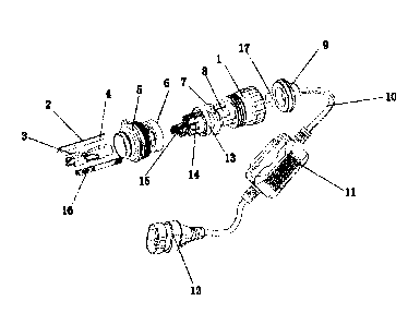
[0016] FIG. 1 is an exploded view of the overall structure of the invention;
[0017] FIG. 2 is a schematic diagram of the overall structure of the
invention;
[0018] FIG. 3 is a schematic diagram of the structure of the red copper lamp
post of the
invention;
[0019] FIG. 4 is a schematic diagram of the structure of the shell of the
invention.
DETAILED DESCRIPTION OF THE PREFERRED EMBODIMENTS
[0020] All the features disclosed in the specification, or all disclosed
methods or steps in the
process, except for mutually exclusive features and/or steps, can be combined
in any manner.
[0021] Any feature disclosed in the specification (including any appended
claims, abstract and
drawings), unless specifically stated, can be replaced by other equivalent or
equivalent
alternative features. That is, unless otherwise stated, each feature is just
one example of a series
3
Date Recue/Date Received 2021-09-17
of equivalent or similar features.
[0022] In the description of the invention, it needs to be understood that the
orientation or
positional relationship indicated by the terms "one end", "the other end",
"outer", "upper",
"inner", "horizontal", "coaxial", "center", "end", "length", "outer end", etc.
are based on the
orientation or positional relationship shown in the drawings, which are only
for the convenience
of describing the invention and simplifying the description, rather than
indicating or implying
that the device or element referred to must have a specific orientation, be
constructed and
operated in a specific orientation, and therefore cannot be understood as a
limitation of the
invention.
[0023] In addition, in the description of the invention, "plurality" means at
least two, such as
two, three, etc., unless otherwise specifically defined.
[0024] The terms such as "upper", "above", "lower", "below" and the like used
in the invention
to indicate a relative position in space are used to describe the relationship
of one unit or feature
relative to another unit or feature as shown in the drawings for the purpose
of facilitating
explanation. The term of the relative position in space may be intended to
include different
orientations of the device in use or operation other than those shown in the
figures. For example,
if the device in the figure is turned over, the unit described as being
"lower" or "below" other
units or features will be "above" the other units or features. Therefore, the
exemplary term
"below" can encompass both above and below orientations. A device can be
oriented in other
ways (rotated by 90 degrees or other orientations), and the space-related
descriptors used in this
article are explained accordingly.
[0025] In the invention, unless otherwise clearly defined and limited, the
terms "provided",
"sleeved", "connected", "through", "plug" and other terms should be
interpreted broadly; for
example, it can be a fixed connection, it can be a detachable connection, or
integrated; it can be
a mechanical connection or an electrical connection; it can be a direct
connection, or an
indirectly connection through an intermediate medium, and it can be an
internal communication
between two elements or the interaction relationship between two elements,
unless specifically
defined otherwise. For those of ordinary skill in the art, the specific
meaning of the above terms
in the invention can be understood according to specific circumstances.
[0026] As shown in FIG. 1 and FIG. 2, an inner circulation heat-dissipating
LED lamp cap of
the invention, comprising a shell 1, a control circuit, and a power supply
circuit, wherein one
side of the shell 1 is connected with a light-emitting component; the outside
of the shell 1 is
installed with a metal holder 5; the inside of the shell 1 is provided with a
heat-dissipating
4
Date Recue/Date Received 2021-09-17
component; the output end of the heat-dissipating component directly faces the
light-emitting
component; the high-pressure airflow generated by the heat-dissipating
component is blown to
the light-emitting component to take away the heat, and then an inner
circulation warming
airflow is formed inside.
[0027] As shown in FIG. 3, the light-emitting component comprises a red copper
lamp post 4;
a flat mounting surface 42 is respectively formed on the upper and lower
surfaces of the red
copper lamp post 4; a hollow cavity 41 is formed inside the red copper lamp
post 4; a copper
substrate 2 is respectively installed on the upper and lower surfaces of the
red copper lamp post
4; one end of the copper substrates 2 respectively extends into the hollow
cavity 41 of the red
copper lamp post 4; the copper substrate 2 is installed with LED chips 16.
[0028] A thermal conductive sheet 3 is provided between the bottom of the
copper substrate 2
and the red copper lamp post 4; the heat on the LED chip 16 is transferred to
the red copper
lamp post 4 through the thermal conductive sheet 3; the thermal conductive
sheet (3) adopts a
preformed tin sheet. In the embodiment, the preformed tin sheet is used as the
thermal
conductive piece, which will greatly improve the heat-conducting ability of
the traditional heat-
conducting glue, so that the heat on the LED chip can be quickly exchanged
with the red copper
lamp post to achieve better heat dissipation.
[0029] After the copper substrate 2 is fixedly installed on the red copper
lamp post 4, the high-
pressure airflow generated by the heat-dissipating component enters from the
air inlet at one
end of the red copper lamp post 4, and passes through the diversion channel at
the upper end of
the copper substrate 2 to take away the heat on the LED chip 16. In this way
of convective
blowing, the temperature will be greatly reduced after the airflow passes
through the diversion
channel with a smaller aperture; at this time, the heat can be quickly taken
away after being
concentrated in contact with the LED chips. This method has better heat
dissipation and rational
use of the structure of the red copper lamp post.
[0030] In the embodiment, the heat-dissipating component adopts a spiral jet
fan 14; the spiral
jet fan 14 and the light-emitting component are connected to the control
circuit and the power
supply circuit. The spiral jet fan forms a high-pressure airflow in the lamp
body, which quickly
blows away the surface and internal temperature of the lamp bead, with better
heat conduction
performance and more stable use of the whole machine.
Date Recue/Date Received 2021-09-17
[0031] The inside of the shell 1 is further provided with an FPC connecting
plate 15; one end
of the shell 1 is riveted with a butt joint 8; the red copper lamp post 4 in
the light-emitting
component is sleeved on the butt joint 8, at this time the FPC connecting
plate 15 is connected
to the copper substrate 2; the other end of the FPC connecting plate 15 is
connected to the
control circuit and the power supply circuit.
[0032] In the embodiment, the spiral jet fan 14 is provided with a fixing
plate 13; one side of
the spiral jet fan 14 is sleeved with a shock-absorbing silicone piece 6, and
the other side thereof
is sleeved with a shock-absorbing fixing silicone piece 7. By arranging a
shock-absorbing
silicone piece on both sides of the spiral jet fan 14, the vibration generated
by the spiral jet fan
14 during operation is smaller, the whole headlights work more quietly, and
the use performance
of the spiral jet fan 14 can be more stable.
[0033] The shell 1 is an aluminum shell; the end of the aluminum shell is
fixed with an
aluminum rear cover 9; the aluminum rear cover 9 is provided with a wire
fixing sleeve 17; a
power control cable 10 penetrates the aluminum rear cover 9 and the wire
fixing sleeve 17 and
is connected to the light-emitting component and the heat-dissipating
component.
[0034] The control circuit and the power supply circuit comprise a drive 11, a
plug 12 and a
power control cable 10; the assembling surface of the metal holder 5 and the
aluminum shell is
provided with more than one silicone sealing ring. As shown in FIG. 4, more
than one annular
groove is provided on the aluminum shell for installing the silicone sealing
ring to increase the
sealing performance of the assembly.
[0035] The invention uses an inner circulation heat-dissipating method in a
sealed automobile
lamp component, and uses the internal air in the automobile lamp component to
circulate heat,
which can not only prevent the life of the cooling fan from being affected by
the external
environment during work, but also achieve the snow melting function when used
in cold areas
in winter, thereby improving driving safety in rain and snow.
[0036] The invention uses high-quality LED lamp beads with a single lumen of
540 lumens,
which is small in size, safe and stable, low in power consumption, high in
efficiency, energy-
saving and environmentally friendly, and is more than ten times that of
ordinary lamps and
HIDs.
[0037] The invention adopts built-in turbine for heat dissipation and
placement, utilizes the air
6
Date Recue/Date Received 2021-09-17
in the space of the sealed automobile lamp component, the independent space of
the turbine of
the lamp body and the high-speed rotation of the fan blades to generate high-
pressure airflow,
which quickly and continuously blows away the surface heat of the lamp beads
by spraying to
the LED lamp beads through the lamp bead diversion channel, and reduces the
heat
accumulation at the heat source to a greater extent;
[0038] At the same time, the high-pressure airflow also cools down the inside
of the substrate
that is attached to the lamp beads, which effectively reduces the temperature
of the outside and
the inside, and achieves the purpose of heat dissipation.
[0039] At the same time, because the lamp works in a sealed automobile lamp
component, the
air in the automobile lamp component is used to circulate heat, and the air in
the automobile
lamp component can be heated to about 70 C within about 20 minutes of work, so
as to realize
that if the automobile lamp component is exposed to use in cold rain and snow,
when ice and
snow cover the surface of the component, the air temperature in the component
can be as high
as 70 C and the surface temperature is also close to 50 C, therefore, the ice
or snow covering
the surface of the component can be melted away, making it safer to drive on
rainy and snowy
days.
[0040] The above are only specific implementations of the invention, but the
protection scope
of the invention is not limited thereto. Any changes or substitutions that are
not thought of
through creative work shall be covered by the protection scope of the
invention. Therefore, the
protection scope of the invention should be subject to the protection scope
defined by the claims.
7
Date Recue/Date Received 2021-09-17