Note: Descriptions are shown in the official language in which they were submitted.
- 1 -
QUICK-HITCH FOR CONSTRUCTION VEHICLE TOOLS
The present invention relates to a quick-hitch forcou piing a tool to an
excavator arm
or to a similar tool manipulator, comprising two hitch halves that can be
latched to-
gether and that comprise at least one pair of latching parts with which a
retractable
and extractable latch is associated, an actuating cylinderbeing provided for
actuating
the latch.
Quick cou plingsforcou piing varioustools, such as rakers, clamshell buckets
ordem-
olition claws, to an excavator arm or similar tool guides such as articulated
arm jibs,
are often used on construction vehicles such as hydrau lic excavators, or
articulated
grabbers such as wood handling machines ordemolition devices, or similar
material
handling machines, in order to be able to use different tools without long
retooling
times.
As latching elements, quick cou plings of th is kind can in particular
comprise two mu-
tually spaced latching shafts on one coupling part, while the other coupling
part, in
particular the coupling part on the excavator arm side, can comprise a
preferably
hook-shaped coupling receptacle for hooking in a first of the two latching
shafts, and
a latching receptacle for latching to the second latching sh aft. After the
first latching
shaft has been hooked into the coupling receptacle, the two coupling parts can
be
pivoted relative to one another, wherein the latching shaft located in the
coupling
receptacle forms the axis of rotation, such that the second latching shaft is
inserted
or pivoted into the latching receptacle, where said second latching shaft can
then be
latched, for example in the man nerof an extensible chock, by means of a
latching
element, such that it is at the same time also no longer possible to move the
first
latching shaft out of the coupling receptacle. In order to move said latching
element
Date Recue/Date Received 2021-09-28
- 2 -
an adjustment actu ator th at is actuated by external energy is provided,
which actuator
can for example be designed as a hydraulic cylinder and is typically
actuatable by
means of hydraulic pressure, from the device.
In this case, said latching shafts on one of the coupling parts can be formed
by latch-
ing bolts which can extend on the corresponding coupling part, in particulars
as to
be mutually parallel, wherein it may also be possible, however, for other
structural
parts of the coupling part, such as protruding lugs, axle journals, engagement
stubs
in the form of protrusions or recesses, for example in the form of pockets, to
be used
as the latching part, instead of such bolts, the shape of which parts is
matched to the
coupling receptacle or the latching receptacle of the other coupling part.
Quick couplings of this kind are also subject to standards with respect to the
dimen-
sions and the latching parts, in order to ensure the compatibility of a
coupling half
used on the excavator arm with various tools on which a coupling half is
mounted
and which, depending on the tool, may originate from various manufacturers and
must be sufficiently compatible with the arm-side coupling half thatthe two
coupling
halves can come together and latch. Standardization of this kind is achieved
for ex-
ample in the form of what is known as the S-coupleror the S-standard, which
sped-
fiesthe dimensions and arrangementofthe latching elements and receiving jaws
and
was specified by the Swedish institute Maskin leverantdrem a and was last
published
on 28 May 2010. Said S-coupler comprises, in the manner described above, two
mutually parallel transverse bolts as latching parts on one coupling half,
while the
other coupling half comprises a jaw-like coupling receptacle on one side, and
an L-
shaped latching receptacle on the otherside, on opposing end faces, which
recepta-
cles can be locked or closed to form a receptacle which isthen also U-shaped
or jaw-
like, by means of a pair of extractable latching bolts.
Further examples of quick couplings of this kind are known from documents EP 1
852 555 A2, DE 20 2012 007 124 U1 and DE 20 2014 001 328 U1.
Date Recue/Date Received 2021-09-28
- 3 -
The transverse bolt, which is moved into a receiving jaw, is usually secured
or fixed
there by a latch, which can be actuated by a hydraulic actuating cylinder. In
this re-
spect, it is known to bias the latch into the latching position by means of a
spring and
to use the hydrauliccylinderon lyforopening,whereas it may also be intended to
use
the actuating cylinder for both latching and unlatching. In both cases, the
latch must
be secured in its latching position to reliably prevent unintentional
unlatching of the
quick-hitch. An option in this case is to latch the actuating cylinder, which
is usually
achieved hydraulically by shutting off the inletto the cylinder chamberthat
drives the
actuating cylinder into the latching position by means of a valve, so that the
pressure
medium in the pressure chamber will no longer be able to escape and thus to
move
to the latching position. Such hydraulic locking is in itself favorable in
terms of the
space required on the cylinder, which is sign ificant since the installation
space avail-
able on the quick-hitch is very limited.
Nevertheless, reliable locking of the latch in the latching position must be
ensured
even if the hydrau lic system of the excavator or the machine to which the
quick-hitch
is attached fails. Yet such a locking device, which is safe against
hydraulicfailures,
on the one hand needs to take into accountthe very limited space available on
the
quick-hitch, and on the other hand, additional components protruding beyond
the
outer contours of the quick-hitch halves should be avoided as far as possible
so as
to avoid providing an attack surface during rough construction site operation,
which
could lead to damage or even breakage of the locking device if it gets caught
on
stones, brickwork and the like.
On the other hand, the locking mechanism muststill be very stable and reliably
with-
stand the high forces acting on the quick-hitch, which in itself precludes a
fragile de-
sign of the locking components. As the entire working forces acting on the
tool, for
example the full working loadsof a grab bucketplunging intothe soil or
subsoil, have
to be carried away via the two transverse bolts of the quick-hitch, there are
concen-
trated very high forces which, though not acting on the bolt in the direction
of the
opening movement, still tug at it. Since the bolts are often wedge-shaped in
order to
Date Recue/Date Received 2021-09-28
- 4 -
force the transverse bolts into the receiving jaws, forces can also be applied
to the
bolt in the opening direction via the wedge surface.
So proceeding from this, it is therefore the underlying object of the present
invention
to provide an improved quick-hitch of the initially named kind which avoids
disad-
vantages of the prior art and furtherdevelops the latter in an advantageous
manner.
In particular, a space-saving locking device that can be integrated into the
installation
space of the quick-hitch is to be created for fixing the latch in the latching
position,
which withstands high forces and is easy and reliable to operate even under
rough
operating conditions.
Said task is solved, according to the invention, with a quick-hitch as claimed
in claim
1. Preferred embodiments of the invention are the subject-matter of the
dependent
claims.
It is therefore proposed to integrate the locking device forfixi ng th e latch
in its latching
position into the actuating cylinder in order to avoid protruding of
additional compo-
nents beyond the outer contours of the quick-hitch and to benefitfrom the
protected
installation position of the actuating cylinder. According to the
invention,the actuating
cylinder has a mechanical blocking unitfor locking the latching position of
the bolt,
having a lead screw which is in a threaded engagement with the piston and/or
the
piston rod of the actuating cylinder, so that the piston is only displaceable
by turning
the lead screw, as well as a releasable anti-rotation device for the lead
screw. Due
to the implementation through the lead screw, very high locking forces on the
bolt
can be absorbed by relatively small reaction forces on the anti-rotation
device. At the
same time, the solid, force transmitting componentsof the actuating
cylinderare used
to lock the latch, so that the latch is reliably secu red withoutrequ irin g
additional space
in the limited installation space on the quick-hitch . The actuating
cylindersimultane-
ously forms the locking device or the mechanical blocking unit and in this
respect
fulfills a dual fu n ction, wherein the actuating cylindercan adjustthe latch
hydraulically
or by means of pressure medium and lock it mechanically.
Date Recue/Date Received 2021-09-28
- 5 -
In further embodiments of the invention, both the lead screw and the anti-
rotation
device may be arranged inside the cylinder so that the mechanical blocking
unit is
fully integrated into the actuating cylinder.
In order to be able to release or engage the anti-rotation device, in an
advantageous
further embodiment of the invention the anti-rotation device can be mounted in
a
rotationally fixed but axially movable manner, so that the lead screw can be
fixed or
released by axial adjustment of the anti-rotation device in the longitudinal
direction of
the cylinder. In principle, the kinematically reversed adjusting of the
spindle in the
axial, i.e. longitudinal, direction of the piston could be considered as an
alternative or
additionally in orderto engage and disengage the spindle with the anti-
rotation device
and thereby fix or release it rotationally. By axially adjusting the anti-
rotation device
and the threaded stem relative to each other, the threaded stem, which is
itself rotat-
ably mounted, can be engaged and disengaged with the non-rotatably mounted
anti-
rotation device.
In an advantageous furtherembodiment of the invention, however, said lead
screw
may be mounted so as to be rotatable but axially fixed, while the anti-
rotation device
is mounted so as to be axially displaceable but rotationally fixed. In this
way there
can be achieved a clearance-free locking of the latch, whereas provision can
be
made for a simple adjustment of the anti-rotation part.
In an advantageous further development of the invention, said anti-rotation
device
may comprise a locking ring or locking plate which may extend at least
approximately
in a plane transverse to the longitudinal axis of the spindle and may be
axially mov-
able in the longitudinal direction of the cylinder, rotationally fixed, in
order to engage
with and disengage from the lead screw and/or a lead screw head by adjustment
in
the axial direction.
On the one hand, such a locking ring or locking plate does not add much weight
in
the axial direction and therefore avoids an increase in the axial length of
the actuating
cylinderor a reduction in the axial travel for a given axial dimension of the
cylinder,
Date Recue/Date Received 2021-09-28
- 6 -
whereas on the other hand, the torque required to secure the lead screw
against
rotation can be well distributed or the forces acting to secure rotation can
be intro-
duced in a distributed manner.
The axially displaceable but rotationally fixed mounting of the locking ring
or of the
anti-rotation element can advantageously take place on the cylinderof the
actuating
cylinder, wherein, forexample, the locking ring or the anti-rotation element
can have
an outer contour which deviates from the circular shape and the displacement
or
installation space of the cylinder in which the anti-rotation element is
accommodated
can have an in ner circumferential wall which deviates from the circu lar sh
ape and on
which the locking ring orthe anti-rotation element is located. For example,
the cylin-
der of the actuating cylindermay have an approximately rectangularor hexagonal
or
elliptical or oval installation space forthe locking ring or latch ing
element, which may
have an outer circumference adapted to be axially displaced but not rotated.
Advan-
tageously, the outer circumferential contourof the locking ring can
substantially cor-
respond to the in nercircumferential contourofthe installation space, so th at
the outer
ring can slide along the wall of the installation ring in a guided manner and
at the
same time is secured against rotation.
As an alternative or in addition to a support against rotation on the in
nerwall of the
cylinder, the anti-rotation element can also be secured against rotation by
separate
sliding guide profiles located in the interior of the actuating cylinder. For
example,
provision can be made for guide rods extending in the longitudinal direction
of the
cylinder, along which there can slide the locking ring orthe anti-rotation
elementwith
the corresponding recesses. Alternatively or additionally, the locking ring
could also
have projecting guide pins which can be slidably guided in guide bores, for
example
in the base of the cylinder head, to allow axial adjustment and prevent
rotation.
In furtherdevelopment of the invention, said locking ring or anti-rotation
elementmay
comprise latching claws and/or latch in g recesses facing the lead screw
and/or a lead
screw head, which may be engaged and disengaged from counter-recesses and/or
counter-claws on the lead screw and/or lead screw head by axial adjustment of
the
Date Recue/Date Received 2021-09-28
- 7 -
anti-rotation elementand lead screw relative to each other in the longitudinal
direction
of the cylinder. Advantageously, a plurality of latching claws may be arranged
in an
an n u larly distributed manners as to be able to engage in claw recesses
which are
also arranged in an an nularly distributed manner.
The anti-rotation device can be designed to lock in opposite directions, or
alterna-
tively on ly in one direction , in particularin such a way that a rotation of
the lead screw,
which occurs when the actuating cylinderdrives the bolt into the latching
position, is
possible even when the anti-rotation device is in latching engagement and the
anti-
rotation device reliably locks only an opposite rotation of the lead screw.
This type of
configuration of the anti-rotation device, locking on one side or in one
direction, can
be similar to that of ratchet spanners, which, forexample, allow a screw to be
turned
clockwise and then slip th rough when it is retightened or reset in the
counterclockwise
direction. Such an anti-rotation device that locks in one direction only
ensures that
the bolt can always be moved by the actuating cylinder in its fully latching
position
withoutthe risk of the anti-rotation device latching too early.
For example, said latching claws, which may be arranged in an
annulardistribution,
may have flanks of differentshapes in the circumferential direction. For
example, on
one side, provision can be made for flanks that are approximately
perpendicularto
the direction of rotation, while the counter-flanks can be configured as wedge
sur-
faces that can be overrun by the counter-contour of the latching engagement
ele-
ments.
In furtherdevelopments of the invention, provision can be made on said locking
ring
or locking plate for latching claws projecting in the axial direction and/or
latching re-
cesses recessed in the axial direction. The counter-contours to this in the
form of
latching recesses and/or latching claws can also be formed on the lead screw
head
and/or on the lead screw itself in an axially projecting and/or recessed
manner.
Alternatively or additionally, however, provision could also be made for
radially pro-
jecting latching claws which can enter radial latching recesses which may be
open
Date Recue/Date Received 2021-09-28
- 8 -
towards an axial side. For example, provision can be made on the locking ring
for
radially inwardly projecting latching claws orteeth which can enter latch ing
recesses
or tooth gaps on the outer circumference of the lead screw, in particularon a
spindle
shoulderoratthe spindle end.
The anti-rotation device can advantageously be actuated by pressure means or
hy-
draulically, in particular axially. For this purpose, the anti-rotation
element, for exam-
ple said locking plate or locking ring, could be configured as a piston and
guided
axially displaceably in a pressure chamber in the cylinder, so that axial
adjustment
can be achieved by applying pressure to the chamber in which the locking ring
or
locking plate is guided displaceably.
Alternatively or additionally, however, the anti-rotation element can also be
adjusted
by separate pistons, for example plunger pistons. In this case, the anti-
rotation de-
vice, for example in the form of said locking plate or locking ring, can be
accommo-
dated in an axially movable manner, in particular guided in a displaceable
manner,
in a movement space inside the actuating cylinder. For axial adjustment,
provision
can advantageously be made for a plurality of actuating elements, for example
in the
form of said plunger pistons, which can, forexample, be guided displaceably in
bore-
hole-shaped pressure chambers in order to project more or less far out of the
bore-
hole-shaped chambers depending on the pressure medium applied.
Instead of hydraulic actuation, itwou Id also be possible, alternatively or
additionally,
to adjust the anti-rotation element axially by actuating elements actuated in
another
way, for example by electromagnetically adjustable actuating elements.
In fu rth erembodiments of the invention, a plu ralityof actuating elements,
for example
3 or 4 or even more than 5 actuating elements, may be arranged distributed
around
the circumference in orderto axially adjust the anti-rotation element.
Advantageously, the anti-rotation element may be biased into its latching
position,
wherein a suitable biasing device may comprise, for example, one or more
spring
Date Recue/Date Received 2021-09-28
- 9 -
elements which attempt to drive the anti-rotation element into the latching
position by
spring force. Hydraulic and/or electromagnetic actuation can be used to
release the
anti-rotation device, which can overcome said spring forces.
The piston and/or piston rod of the actuating cylinder may have a spindle
recess into
which the lead screw may extend, or which allows the piston and/or piston rod
to be
driven over the lead screw. In this case, provision can be made on the piston
and/or
on the piston rod for a thread which is in screw engagementwith the thread of
the
lead screw.
The anti-rotation device can be arranged in the area of a cylinder base which
is lo-
cated at the end of the pressure chamber acting on the piston, wherein this
can in
particular be the side facing away from the piston rod.
In order to make good use of the installation space available on thequ ick-h
itch halves
and to create a secure arrangement, the actuating and locking cylinder can
advanta-
geously be accommodated in an interior space of one hitch half between its
outer
walls, wherein the actuating and locking cylindercan be positioned in
particular be-
tween two receiving jaws into which the other hitch half can be inserted with
trans-
verse bolts or transverse profiles attached thereto.
In this case, the actuating and locking cylinder can advantageously be
installed tilted
at an angle with respect to a plane which is determined by the transverse bolt
axes
passing through the receiving jaws. In particular, the inclined actuator and
locking
cylinder assembly can be so oriented that the cylinder longitudinal axis
extends past
the two receiving jaws at an acute angle such that the cylinder longitudinal
axis
passes the top of one receiving jaw and the bottom of the other, or passes on
oppo-
site sides of the receiving jaws.
Advantageously, said receiving jaws on the hitch half on which the locking
cylinder is
provided may be open to differentsides, for example, a first receiving jaw
having it
opening looking away from the second receiving jaw and said second receiving
jaw
Date Recue/Date Received 2021-09-28
- 10 -
having its opening looking approximately transversely of the plane joining the
two
receiving jaws. If the quick-hitch half is arranged in such a way th at the
two receiving
jaw lie approximately in a horizontal plane, a receiving jaw then lying on the
right can
be open to the right, while the left receiving jaw is open downwards, wherein
in this
case or with this align mentthe latch can be displaced approximately
horizontally or
inclined at an acute angle thereto in order to be able to close the receiving
jaw open
downwards or to be able to block it to such an extent that a transverse bolt
received
therein is caught.
Advantageously, the two pairs of latching parts, which may each be formed by a
receiving jaw and a bolt part receivable therein, are such that the two hitch
halves
may be hooked or coupled to each other on a first pair of latching parts and
the sec-
ond pairof latching parts may be moved together or coupled into each other by
twist-
ing the two hitch halves about the coupled, first pair of latching parts. Said
latch then
latches the second pair of latching parts in the coupled position.
The invention isexplained in more detail below on the basis of a preferred
exemplary
embodiment and the corresponding drawings. The drawings show:
FIG. 1: is a schematic side view of a quick-hitch according to an advantageous
em-
bodiment of the invention, which quick-hitch is attached to a jib arm of an
excavator and a grab bucket is coupled as an add-on tool,
FIG. 2: is a perspective view of the quick-hitch from FIG. 1 in an uncoupled
position
in which the two hitch halves that can be coupled together are shown shortly
before being hooked onto the hook portion,
FIGS. 3a and 3b : are each a perspective view of the two hitch halves, showing
en-
ergy coupling parts attached to each hitch half, wherein partial view FIG 3a
shows the hitch half which is mounted on the excavator arm and on which a
coupling carrier is rigidly mounted, and partial view FIG 3b shows a tool-side
hitch half on which a coupling carrier is mounted in a rubber-elastic manner,
Date Recue/Date Received 2021-09-28
- 11 -
FIG. 4: is a perspective view of the two hitch halves in the state when
coupled to-
gether but not yet pivoted together,
FIG. 5: a perspective, partially cutaway view of the quick-hitch showing the
arrange-
ment of the actuating and locking cylinderforactuating the latch for the sec-
ond latching bolt, wherein partial view a shows the actuating and locking cyl-
inder in interaction with the quick-hitch halves and the grab bucket attached
thereto, and partial view b is an enlarged, cutaway view of the actuating and
locking cylinder,
FIG. 6: a perspective longitudinal sectional view of the actuating and locking
cylinder
of the preceding figures,
FIG. 7: a partial, enlarged perspective longitudinal sectional view of the
anti-rotation
device for the lead screw of the actuating and locking cylinder, and
FIG. 8: a perspective view of the anti-rotation elementfor locking the lead
screw.
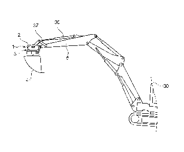
As shown in figure 1, the quick-hitch 1 can be mounted between the free end of
the
jib arm 5 of an excavator 30 and the tool 4 that is to be attached thereto,
wherein said
add-on tool 4 can be designed forexample as a grab bucket, as is shown in
figure 1,
but which can, in a manner conventional per se, also comprise other
construction,
handling ordemolition tools, forexample in the form of clamshell buckets,
demolition
jaws, pincers, or the like.
In this case, said quick-hitch 1 can be able to be mounted on said jib arm 5 ,
by
means of an arm-side hitch half 2 , so as to be pivotable about a horizontal
pivot ads
that is oriented transversely to the longitudinal axis of the jib arm 5 , such
that the
quick coupling I, together with the tool 4 attached thereto, can be pivoted
relative to
the jib arm 5 for example by means of a pressure medium cylinder 36 and an
inter-
posed pivot piece 37.
Date Recue/Date Received 2021-09-28
- 12 -
A tool-side hitch half 3 (cf. figure 2) can be attached to the add-on tool 4
and/or an
interposed rotary drive.
As shown in figure 2, the two hitch halves 2 and 3 comprise two pairs of
latching parts
that can be latched together and that allow for a two-stage coupling or
latching pro-
cess. Firstly, one pair of latching elements is hooked in or coupled, in order
to then
pivot the two hitch halvestogetheraboutthe cou pled first latching pair. In
the pivoted -
together cou piing position , the second pair of latching parts are then
latched together,
cf. a comparison of figures 4 and 5.
As shown in figure 2, one hitch half, in particularthe arm-side hitch half 2,
can com-
prise, as latching parts, a coupling receptacle 6 and a displaceable latch 11
that can
be moved in front of the opening of a latching receptacle 10, wherein said
latching
receptacle 10 can have a different opening direction from the coupling
receptacle. In
particular, the coupling receptacle 6 can be open in the direction facing away
from
the latching receptacle 10 ,while the latching receptacle 10 can be designed
so as
to be open towards the other hitch half 3 . However, as an alternative to the
embod-
imentshown in the figures, according to figure 2, the second latching partof
the hitch
half 2 could also comprise a latching jaw that is displaceable as a whole, as
is known
per se. The latch 11 can be displaceable approximately in a direction
transversely to
the opening of the latching receptacle 10 , in order to be able to be pushed
in frontof
said opening. For example, the latch 11 can be moved into the latching
receptacle
from above, so as to be slightly obliquely inclined.
The other hitch half, in particular the tool-side hitch half 3, can comprise
two trans-
verse bolts 33 and 34 as latching parts which can be oriented so as to be in
parallel
with one anotherandmutuallyspaced to such an extentthatthey fit into the
openings
of the coupling and latching receptacles 6 and 10.
In order to couplethe two hitch halves 2 and 3 together, firstly the coupling
receptade
6 is suspended on the transverse bolt 33 , wherein a securing element 7 can
capture
Date Recue/Date Received 2021-09-28
- 13 -
or secure the transverse bolt 33 in the coupling receptacle 6 in order to
prevent said
bolt from inadvertently slipping out when the two hitch halves 2 and 3 are
pivoted
together. Said securing element 7 can for example be spring-preloaded and
opened
by a pressure actuator when the quick-hitch is intended to be decou pled.
If the coupling receptacle 6 is suspended on the transverse bolt 33 , as is
shown in
figure 4, the two hitch halves 2 and 3 can be pivoted towards one another
aboutthe
pivot axis formed by the suspended coupling receptacle 6 or the transverse
bolt 33
captured therein, as far as the coupling position shown in figure 5. In the
mentioned
coupling position according to figure 5, the second transverse bolt 34 is
inserted into
the latching receptacle 10 such that the latch 11 can be moved into the
latching po-
sition in order to secure or fix the transverse bolt 34 in the latching
receptacle 10 .
The latch 11 is actuated by a pressure fluid cylinder 8, which will be
discussed in
furtherdetail below.
As shown in figures 4 and 5, energy coupling parts 12 and 13 can be provided
on a
portion of the hitch halves 2 and 3 that is spaced apart from the coupling
receptacle
6 , which energycou piing parts can in particular be arranged on an end
portion of the
hitch halves 2 and 3 that is opposite the coupling receptacle 6.
Said energy coupling parts 12 and 13 can be hydraulic couplings for example.
Irre-
spective thereof, the energy coupling parts 12 and 13 can be designed as plug-
in
couplings which can be moved into one another and can comprise coupling
sleeves
and coupling pins thatcan be inserted therein.
As figure 5 shows, it may be advantageous for the actuating cylinder 8 to be
con-
nected by its piston rod 9 to said latch 11 and to be supported and/or fixed
to the
hitch half 2 by its cylinder12, from which the piston rod 9 is extractable.
For example,
the hitch half 2 may comprise a receiving pocket 13 in which the cylinder 12
is seated,
wherein a support 14 may be provided at one end of the receiving pocket 13
against
which the cylinder 12 may be axially supported. In principle, however, the
actuating
Date Recue/Date Received 2021-09-28
- 14 -
cylinder 8 could alternatively or additionally be bolted to the hitch half 2,
for example,
whilst a corresponding bearing eye could be provided on the cylinder 12.
As figure 5 shows, the actuating cylinder 8 may be inclined at an acute angle
to a
plane defined by the two coupling and latching receptacles 6 and 10, in
particular
transverse pin axes passing thereth rough, so that the longitudinal axis of
the actuat-
ing cylinder 8 passes on opposite sides of the coupling and latching
receptacles 6
and 10. In particular, the actuating cylinder 8 may have an end portion
positioned
above the coupling receptacle 6, while the latch-side end of the cylinder 12
or the
latch 11 may be positioned below the latching receptacle 10.
Overall, the actuating and locking cylinder 8 has a protected receptacle in an
interior
of the hitch half 2 and, in the coupled state of the quick-hitch 1, is
enclosed by the
outer peripheral contou rs or walls of the hitch halves 2 and 3 and is thereby
protected.
In particular, the lateral frame plates of the hitch halves 2 and 3 may
laterally enclose
the actuating cylinder 8.
As shown in figures 5 to 8, a blocking or locking unit15 is integrated into
the actuating
cylinder 8, which can fix the actuating cylinder 8 in one or more extension
positions
and, in particular, arrest the latch 11 in its latching position.
In this respect, said mechanical blocking device 15 of the actuating and
locking cyl-
inder 8 comprises a lead screw 16 which can be housed in the interiorof the
cylinder
12 and can be in threaded engagementwith the piston 17 and/or the piston rod 9
of
the actuating cylinder 8. For example, as figure 7 illustrates, the piston 17
may have
an internal screw thread which is in screw engagement with an external thread
of the
lead screw 16 so that axial movement of the piston 17 involves rotation of the
lead
screw 16. Said piston 17 is moved in the cylinder 12 in a mann er known as
such by
pressurization, wherein the actuating cylinder 8 can advantageously be of
double-
acting design. Depending on whetherthe an n ularchamber18 su rrou nding the
piston
rod 9 or the pressure chamber 19 facing away from the piston rod 9 is
pressurized
with pressure medium, the piston 17 retracts or extends. The piston 17 is
guided in
Date Recue/Date Received 2021-09-28
- 15 -
a non-rotatable manner, for example via the piston rod 9, which can be secured
against rotation by its attachment to the latch 11 or also by the
corresponding config-
uration of the outlet opening on the cylinder collar. Hereby an axial movement
of the
piston 17 leads to a rotation of the lead screw 16.
The lead screw 16 may be axially fixed but rotatably mounted in the cylinder
12, for
example by means of a lead screw head 20 which may be non-rotatably connected
to the lead screw 16 and rotatably mounted in the cylinder 12.
Due to the screw engagement between piston 17 and lead screw 16 and their bear-
ings, piston 17 can only be moved axially if lead screw 16 can rotate. In
order to lock
the actuating cylinder 8, i.e. to freeze the piston 17 in its respective axial
position, the
lead screw 16 can be fixed against rotation by means of an anti-rotation
device 21
which can block the rotational degree of freedom of the lead screw 16.
For this purpose, said anti-rotation device 21 comprises an anti-rotation
element 22
which is also received in the cylinder 12 and is axially displaceable therein,
but is
rotationally fixed, so as to be brought into and out of latching
engagementwith the
lead screw 16 or the lead screw head 20 connected thereto by axial
displacement.
As figure 8 shows, the anti-rotation element 22 may advantageously comprise an
at
least approximately plate-shaped locking ring 23 which may embrace the lead
screw
head 20 and extend transversely to the longitudinal direction ofthe actuating
cylinder.
In this regard, the locking ring 23 is axially slidably received in an
installation space
24 which may form part of the cylinder 12. In order to secure the locking ring
24
against rotation, but to keep it axially displaceable, the locking ring 23 may
have an
outer contour deviating from the circular shape, for example by having one or
more
flatten ings atthe circumference and/or an overall oval and/orelliptical or
polygon-like
multi-angular design. In a corresponding manner, said installation space 24
may
Date Recue/Date Received 2021-09-28
- 16 -
have an in nercircumferential contouring deviating from the circularshape,
forexam-
ple having one or more flatten ings and/or having an oval or elliptical or
polygon-like
mu lti-angu lar corresponding to the contouring of the locking ring.
Advantageously, the pairing of the outer and inner circumferential surfaces of
the
locking ring 23 and the installation space 24 simultaneously forms a
displacement
guide and an anti-rotation device, and in particulara (not
circular)cylindrical contour-
ing in the man nerof a prism can be provided.
However, as an alternative or in addition to anti-rotation via the
circumferential walls,
separate longitudinal sliding guide elements could also be provided, for
example in
the form of longitudinal rods parallel to the longitudinal axis of the
cylinder, which can
engage in guide recesses 25 on the anti-rotation e1ement22, for example in the
form
of guide grooves open towards the outer circumference, as shown in figure 8.
The anti-rotation e1ement22, which may be in the form of the locking ring 23
shown,
could in principle be axially adjusted by the application of pressure, a
corresponding
pressure chamber being formed by the installation space 24. Alternatively,
however,
separate displacementelements may be provided, for example in the form of
plunger
pistons, the displacementof which results in an axial displacementof the
locking ring
23 or the anti-rotation element 22. For this purpose, for example, bores 26
can be
provided in a cylinderwall, in which said plunger pistons 27 are accommodated,
so
that they can be moved by pressurizing the bores in order to thereby axially
displace
the locking ring 23.
In this regard, the anti-rotation element 22 may be biased into the latching
position
by a preloading device 28, wherein the preloading device 28 may comprise, for
ex-
ample, one or more spring means for urging the locking ring 23 axially into
the latch-
ing blocking position by spring force.
In order to lock the threaded spindle 16, provision can be made on the
latching ele-
ment 26 and the lead screw head 20 for interlocking latching contours, in
particular
Date Recue/Date Received 2021-09-28
- 17 -
in the form of latching claws 29 and latching recesses adapted thereto in
terms of
shape, into which the latching claws 28 can retract. Said latching claws 28
and the
cooperating latching recesses may be provided on the locking ring 23 and the
lead
screw head 20, in particular projecting or machined in the axial direction.
For exam-
ple, provision can be made on the locking ring 23 for a plurality of axially
projecting
latching claws 28 distributed in the circumferential direction, which can
enter latching
recesses in an end face of the lead screw head 20 facing the locking ring 23.
As figure 8 shows, the latching contours can be configured to lock reliably on
one
side or in one direction only, wherein said latching claws 28 can have flanks
which
rise in a wedge shape towards one side and can thus be driven over, while
locking
flanks, for example perpendicularto the circumferential direction, can be
provided on
the opposite side. This makes it possible to continue turning the lead screw
in one
direction even when the locking ring 23 is actually preloaded into the
latching position,
wherein the latching connection continues slipping. In the opposite direction,
how-
ever, the lead screw is reliably locked.
Date Recue/Date Received 2021-09-28