Note: Descriptions are shown in the official language in which they were submitted.
WO 2020/202093
PCT/1132020/053196
COUPLER FOR MICROWAVE PYROLYSIS SYSTEMS
TECHNICAL FIELD
The present invention relates to the field of pyrolysis, and more particularly
to a coupler for
microwave pyrolysis systems.
BACKGROUND
Pyrolysis of products such as biomass and plastics is usually performed in a
reactor by adding
energy under anaerobic condition, i.e. in an atmosphere deprived of oxygen.
There are usually
three reaction products: oil, gas and carbon black. In most cases, the
pyrolysis process is tuned to
maximize the oil yield since it usually has the most value as a source of
chemicals or fuel.
The conventional heating source for pyrolysis usually comprises combustion of
a fuel-gas to make
a flame and hot combustion gases or resistive electrical heating elements. In
such conventional
pyrolysis systems, the external surface of the reactor is heated so that heat
can be transferred to
the product to be pyrolyzed via heat conduction through the reactor walls.
However, at least some of the conventional pyrolysis systems have at least
some of the following
drawbacks.
At least some of the conventional pyrolysis systems provide low oil yield
because the heating rate
of the product to be pyrolyzed is relatively low, which results in low oil
yield. This is due to the
fact that the heating rate of the product is determined by the temperature of
the vessel wall. i.e. the
higher the vessel wall temperature, the higher the product heating rate. The
maximum vessel wall
heating rate and therefore the final temperature of the product are usually
determined by thermal
inertia of the vessel, the heat source power, the heat losses, the selection
of vessel wall alloy, the
surface area and the heat transfer coefficient All these constraints limit the
heating rate of the
feedstock. However, selection of alloys that can sustain high temperatures
(such as Inconellm or
titanium) increase the capital cost of the system.
Furthermore, low final product temperatures (i.e. low reaction temperatures)
result in low reaction
rates and also affect the kinetics. Also, since the reactor wall is heated to
a temperature higher
- 1 -
CA 03132345 2021- 10-4
WO 2020/202093
PCT/1132020/053196
than the product to be pyrolyzed, the product experiences an increase in
temperature as it leaves
the reactor wall, which may cause degradation of the product.
In order to overcome at least some the above-described deficiencies of
conventional pyrolysis
systems, microwave pyrolysis systems have been developed. Such microwave
pyrolysis systems
use microwaves to heat a product to be pyrolyzed placed into a reactor.
Some of the main advantages of microwave pyrolysis systems over conventional
pyrolysis
systems include high heating rates which lead to high oil yields, high
reaction site temperatures
which leads to high reaction rates and improves the kinetics, and low
environment temperatures
which allows avoiding the degradation of the product of the pyrolysis
reaction.
However, some issues with microwave pyrolysis systems exist. One of these
issues is directed to
the means by which the microwave power is delivered to the reactor. The
challenge in power
delivery resides in the presence of high intensity electrical fields and the
presence of contaminants
in chemical reactors.
Usually microwave pyrolysis systems include a microwave waveguide for
propagating the
microwaves generated by a microwave generator up to the reactor in which
pyrolysis will occur.
The usual waveguides are rectangular pipes of which the dimensions are set by
the microwave
wavelength/frequency and microwave reactors generally have internal dimensions
that are greater
than those of the waveguide. Therefore, the microwave power density is
generally greater inside
the waveguide (smaller volume) than in the microwave reactor.
At a fixed position inside the reactor and the waveguide, one would experience
an electrical and
magnetic potential that oscillates in time. If the potential increases above
the breakdown voltage
of the media, an electrical arc is formed. The electrical arc increases the
temperature of the gas
and produces a plasma. The plasma is electrically conductive and the
oscillating electrical field
sustains the electrical arc, which travels in the direction of the highest
power density, i.e, in
direction of the microwave generator. As it travels towards the microwave
generator, the arc
damages the metal surfaces and boundaries it touches, i.e. the arc produces
sharp edges on metals.
The arc can be killed by stopping the microwave injection. Once the microwave
injection is
resumed, the presence of the sharp edges produced by The previous arc creates
points of high
electrical field intensity, which increases the risk of going beyond the
medium breakdown voltage
- 2 -
CA 03132345 2021- 10-4
WO 2020/202093
PCT/1132020/053196
and promotes the production of another arc. Therefore, the production of arcs
leads to higher
probabilities of arcing. Since the power density inside the waveguide is
usually higher compared
to the microwave reactor, the risk of arcing inside the waveguide is higher
than in the reactor.
Therefore, the waveguide environment must be well controlled (cleanliness,
high breakdown
voltage, no contamination, smooth surfaces, no sharp edges, etc.).
Pyrolysis is usually accompanied with side reactions that produce carbon black
particles. These
particles are electrically conductive, fine solid particles. When in
suspension in a gas, the presence
of carbon black particles decreases the gas breakdown voltage and promotes
arcing. The presence
of other gases and/or liquid produced by the reaction may also decrease the
medium breakdown
voltage.
Contaminants deposition on the metal surfaces may also lead to hot spots and
arcing. For
example, in a fixed carbon black particle, an oscillating electrical field
will induce an electrical
current. Since the electrical resistance of a carbon black particle is not
zero, the carbon black
particle heats up due to resistive losses. Hot spots may therefore be produced
on metal surfaces,
which may lead to surface damage, surface melting, sharp edges and/or arcing.
Regarding couplers used in usual microwave pyrolysis systems, some issues
remain. Usually a
coupler comprises a physical barrier which should present a low dielectric
loss for preventing the
dissipation of microwave energy into heat. The process therefore loses
efficiency and the barrier
is likely to be damaged by the temperature increase (e.g. barrier melting due
to the high
temperature and failure from thermal shock).
Some usual couplers use a flow of an inert gas (e.g. nitrogen) from the
waveguide to the reactor to
create the physical barrier. Such a physical barrier can be used for reactors
for which the coupler
is located in a gas medium otherwise liquids or solids would flow into the
waveguide. Such an
inert gas barrier requires a high flow of gas, which adds cost for the gas
production, and also
separation downstream from the pyrolysis products. Furthermore, it may be
difficult to prevent
contamination from entering the waveguide since pressure fluctuations in the
reactor may entrain
contaminants into the waveguide.
Some other usual couplers use TeflonTm windows as physical barriers, which
have a typical
operating temperature of 260 C. This relatively low operating temperature
limits the applicability
- 3 -
CA 03132345 2021- 10-4
WO 2020/202093
PCT/1132020/053196
of TeflonTm to low temperature chemical processes. Furthermore, deposition of
contaminants such
as carbon black particles on a Teflon" window may result in hot spots on the
Teflonirm window
surface, which may melt and damage the Teflon mi window. Damage to the
TeflonTm window
jeopardizes the ability of the physical barrier from preventing contaminants
from entering the
waveguide. Furthermore, damage to the Teflon window creates zones where solid
contaminants
are more likely to accumulate leading to more hot spots and arcing across the
Teflon window
because the solid contaminants can make a conductive path.
Other types of couplers use quartz windows. Quartz has an operating
temperature in the range of
1400 C. However, in the case of an arc, a quartz window may not sustain the
high temperature of
the arc and may therefore be damaged. The effects of this damage are the same
as the above-
described damages for TeflonTm.
Conventional microwave pyrolysis systems use microwave waveguides having a
rectangular
cross-sectional shape. In such as a rectangular microwave waveguide, the
highest electrical field
intensity is located at the middle of the long edge of the waveguide. This
corresponds to the TEio
transmission mode, which is the dominant mode for rectangular waveguides. In
this case, the
deposition of contaminants may lead to hot spots on the metal, metal damage,
product of sharp
edges and/or arcing.
Furthermore, impedance matching in microwave systems is usually required to
maximize the
transmitted power from the microwave generator to the reactor and minimize the
reflected power.
Impedance matching is usually performed using an iris or stub tuners. The iris
is a perforated plate
and its impedance is a function of the hole size and geometry. Since both size
and geometry are
fixed, the impedance of an iris is fixed and may not be changed in real-time
during microwave
injection into the reactor. An iris is therefore a static impedance matching
system.
A tub tuner usually consists of a waveguide section provided with cylindrical
stubs (usually 3
stubs) or plungers that are inserted along its long edge. The insertion depth
can be varied to
change the characteristic impedance of the tuner. Most stub tuners allow the
changing of each
individual stub's insertion depth in real-time during microwave injection. A
stub tuner is therefore
a dynamic impedance matching system.
- 4 -
CA 03132345 2021- 10-4
WO 2020/202093
PCT/1132020/053196
When they are inserted in the microwave field, the stubs are subjected to an
electrical and
magnetic field, which induces an electrical current on the stub surface. Since
the stub material has
a non-zero electrical resistance (stubs are usually made of aluminum or
copper), resistive heat
losses occur on the stubs. Some resistive losses also occur on the waveguide
wall, but it is
negligible compared to the losses on the stubs. Due to those resistive losses
on the stubs, the stubs
heat up and its temperature increases. As the stub temperature increases, the
stub undergoes
thermal expansion such that its length and diameter increases. Because of the
thermal expansion,
the stub may get squeezed inside the stub casing and may no longer be moved in
and out of the
tuner. The system then loses its ability to change the tuner's impedance.
Furthermore, forcing the
stub to move or out may cause mechanical damage to the stub and stub casing.
Therefore, there is a need for an improved microwave pyrolysis system
including an improved
coupler used for injecting microwaves into a reactor, that overcomes at least
some of the above-
identified drawbacks of prior art systems.
SUIVIMARY
According to a broad aspect, there is provided a coupler for propagating
microwaves into a
microwave pyrolysis reactor, the coupler comprising: an elongated hollow body
for propagating
the microwaves, the elongated hollow body extending between a receiving end
for receiving the
microwaves and a transmitting end mountable to the microwave pyrolysis reactor
for propagating
the microwaves therein, the receiving end having a rectangular cross-sectional
shape and the
transmitting end having a circular cross-sectional shape, a shape of the
elongated allow body
being designed so as to convert a transverse (TE) mode of propagation for the
microwaves at the
receiving end thereof into a linearly polarized (LP) mode of propagation for
the microwaves at the
transmitting end thereof; and a barrier body inserted into the hollow body for
isolating the
receiving end of the elongated hollow body from the transmitting end thereof.
In one embodiment, the elongated hollow body comprises: a mode conversion body
for receiving
the microwaves and converting the TE mode of propagation of the received
microwaves into the
LP mode of propagation; and a connection body mountable to the microwave
pyrolysis reactor for
propagating the microwaves having the LP mode of propagation therein, the
connection body
being hollow and the barrier body being inserted into the connection body.
- 5 -
CA 03132345 2021- 10-4
WO 2020/202093
PCT/1132020/053196
In one embodiment, the mode conversion body comprises a hollow and tapered
body defining a
conversion cavity extending therethrough, and the connection body comprises a
tubular body
defining a receiving cavity, the barrier body being inserted into the
receiving cavity.
In one embodiment, the hollow and tapered body extends between a first end
having a rectangular
shape for receiving the microwaves and a second end having a circular shape
for coupling the
microwaves into the connection body, a shape of the hollow and tapered body
being tapered
between the first and second ends thereof for converting the TE mode of
propagation into the LP
mode of propagation.
In one embodiment, a cross-sectional size of the first end of the hollow and
tapered body is less
than a cross-sectional size of the second end of the hollow and tapered body.
In one embodiment, the tubular body comprises an internal cylindrical surface
surrounding the
receiving cavity, at least a section of the internal cylindrical surface being
tapered, and wherein a
lateral surface of the barrier body is tapered so that the barrier body has a
truncated conical shape
and the barrier body is inserted into the receiving cavity.
In one embodiment, the tubular body extends longitudinally between a first end
connected to the
mode conversion body and a second end mountable to the microwave pyrolysis
reactor, an
internal diameter of the first end of the tubular body being greater than an
internal diameter of the
second end of the tubular body.
In one embodiment, the coupler further comprises a seal body having a tapered
tubular shape, the
seal body being inserted into the tubular body and the barrier body being
inserted into the seal
body.
In one embodiment, the coupler further comprises a backup body having a
tubular shape inserted
into the tubular body so that the barrier body be positioned between the
backup body and the
second end of the tubular body.
In one embodiment, the tubular body extends longitudinally between a first end
connected to the
mode conversion body and a second end mountable to the microwave pyrolysis
reactor, an
internal diameter of the second end of the tubular body being greater than an
internal diameter of
the first end of the tubular body.
- 6 -
CA 03132345 2021- 10-4
WO 2020/202093
PCT/1132020/053196
In one embodiment, the coupler further comprises a seal body having a tapered
tubular shape, the
seal body being inserted into the tubular body and the bather body being
inserted into the seal
body.
In one embodiment, an internal diameter of the tubular body is at least equal
to a wavelength of
the microwaves.
In one embodiment, a length of the hollow and tapered body is longer than half
of the wavelength
of the microwaves and shorter than 5 times the wavelength of the microwaves.
In one embodiment, the mode conversion body and the connection body are
integral.
In one embodiment, the mode conversion body and the connection body are
removably secured
together.
In one embodiment, the coupler further comprises a gasket inserted between the
mode conversion
body and the connection body.
In one embodiment, the coupler further comprises a port for injecting a fluid
within the coupler.
In one embodiment, the port is located on the mode conversion body.
In one embodiment, the barrier body is made of a material that at least one of
maximizes a
microwave transmission and reduces a dissipation of microwave energy.
In one embodiment, the barrier body is made of one of: Teflon, aluminum oxide,
silicon nitride
and quartz.
Microwaves are electromagnetic waves: a traveling electrical field
perpendicular to a magnetic
field. Microwaves used for heating applications have frequencies of 2.45 GHz
(low power below
15 kW) and 915 MHz (high power as high as 100 kW) ¨ these frequencies are
fixed and
determined by international regulations
BRIEF DESCRIPTION OF THE DRAWINGS
Further features and advantages of the present invention will become apparent
from the following
detailed description, taken in combination with the appended drawings, in
which:
- 7 -
CA 03132345 2021- 10-4
WO 2020/202093
PCT/11112020/053196
Figure 1 is a cross-section of a microwave pyrolysis system comprising a
microwave pyrolysis
reactor, a coupler and a tuner, in accordance with a first embodiment;
Figure 2-5 illustrate different views of the microwave pyrolysis reactor of
Figure 1;
Figure 6 illustrates a microwave absorbing particle, in accordance with an
embodiment;
Figure 7 illustrates the heating of a reactant particle, in accordance with an
embodiment;
Figure 8 illustrates a microwave pyrolysis reactor provided with an agitator
device, in accordance
with an embodiment;
Figure 9 is a flow chart of a method for pyrolyzing a product, in accordance
with an embodiment;
Figure 10 illustrates a microwave pyrolysis system comprising a mixing tank
for performing the
method of Figure 8, in accordance with an embodiment;
Figures 11 and 12 illustrate the mixing tank of Figure 10;
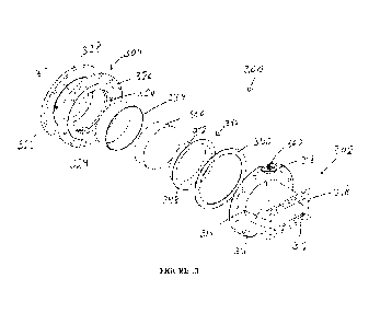
Figures 13 and 14 are exploded views of a coupler for injecting microwaves
into a microwave
pyrolysis reactor, in accordance with a first embodiment;
Figure 15 illustrates the coupler of Figures 13 and 14 once assembled;
Figures 16 and 17 are exploded views of a coupler for injecting microwaves
into a microwave
pyrolysis reactor, in accordance with a second embodiment; and
Figure 18 illustrates the coupler of Figure 15 from which a connection plate
has been omitted to
form a protruding design, in accordance with an embodiment.
It will be noted that throughout the appended drawings, like features are
identified by like
reference numerals.
DETAILED DESCRIPTION
Figure 1 illustrates one embodiment of a microwave pyrolysis system 10 which
comprises a
reactor or vessel 12, a coupler 14 and a tuner 16. It should be understood
that the tuner 16 is
connectable to a source of microwaves or microwave generator (not shown)
either directly or via
- 8 -
CA 03132345 2021- 10-4
WO 2020/202093
PCT/1132020/053196
a microwave waveguide. In the illustrated embodiment, the tuner 16 is used for
guiding the
microwave emitted by the microwave generator up to the coupler 14. The tuner
16 may further be
used for adjusting the power of the energy of the microwaves delivered to the
coupler 16 and
therefore to the reactor 12. The coupler 14 is used for propagating the
microwaves coming from
the tuner 16 into the reactor 12. The reactor 12 is configured for receiving
therein a product to be
pyrolyzed which is heated by microwave heating.
Referring to Figures 2 to 5, there is illustrated one embodiment for the
reactor 12. The reactor 12
is configured for performing chemical and/or physical reactions therein under
the action of
microwave energy.
In the illustrated embodiment, the reactor 12 comprises a tubular body 52
extending along a
longitudinal axis between a first or bottom end 53a and a second or top end
53b, a bottom body or
floor 54 and a top body or cover 56. The tubular body 52 defines a cavity 57
in which the product
to be pyrolyzed is to be received. The bottom body 54 is secured to the bottom
end 53a of the
tubular body 52 and has a size that is at least equal to the cross-sectional
size of the bottom end of
the cavity 57 so as to close the bottom end 53a of the tubular body 52. The
top body 56 is secured
to the top end 53b of the tubular body 52 and has a size that is at least
equal to the cross-sectional
size of the bottom end of the cavity 57 so as to close the top end 53b of the
tubular body 52. When
the bottom and top bodies 54 and 56 are secured to the tubular body 52, the
assembly form an
enclosure in which the product to be pyrolyzed is placed. In one embodiment,
the connections
between the tubular body 52 and the bottom and top bodies 54 and 56 are
substantially hermetical
so than no fluid may exit the enclosure. For example, gaskets may be
positioned between the
tubular body 52 and the bottom and top bodies 54 and 56 for ensuring that the
enclosure is
substantially hermetically closed.
The reactor 12 is provided with a first aperture 58 through which microwaves
are injected into the
interior space of the reactor 12. A microwave guiding device operatively
connected to the source
of microwaves is securable to the external face of the tubular body 52 around
the aperture 58 for
propagating the microwaves from the source of microwaves into the cavity 57.
In the illustrated
embodiment, a connection plate 60 projects from the external face of the
tubular body 52 around
the aperture 58. The connection plate 60 is provided with a plurality of bolts
or rods 62 which
each protrude outwardly from the connection plate 60. In this case, the
microwave guiding device
- 9 -
CA 03132345 2021- 10-4
WO 2020/202093
PCT/1132020/053196
is provided with a connection plate mating the connection plate 60 and
provided with holes
therethrough, each for receiving a respective bolt 62 therein in order to
secure the microwave
guiding device to the reactor 12.
In one embodiment, the microwave guiding device is a microwave waveguide. In
another
embodiment, the microwave guiding device is a coupler such as coupler 14.
In one embodiment, the aperture 58 has a circular shape as illustrated in
Figure 2. In another
embodiment, the aperture 58 is provided with a rectangular shape such as a
square shape. It
should be understood that the shape of the aperture 58 is chosen as a function
of the microwave
guiding device to be secured to the reactor 12 for propagating microwaves
therein.
In one embodiment, the aperture 58 is provided on the tubular body 52 adjacent
to the bottom end
thereof In one embodiment such as an embodiment in which the reactor 12 is
used for pyrolyzing
a liquid or slurry product, the reactor 12 is provided with a fill level 66
representing a desired
level of product or a minimal level of product within the reactor 12. In this
case, the position of
the aperture 58 is chosen to be below the fill level 66, as illustrated in
Figure 3.
While Figures 1-5 illustrate the aperture 58 provided on the tubular body 52,
the person skilled in
the art would understand that the aperture for injecting the microwaves into
the reactor 12 may be
provided on the bottom body 54 or the top body 56.
In one embodiment, at least a section of the tubular body 52 is configured for
receiving and
propagating a temperature control fluid therein in order to control the
temperature of the reactor
12 and/or the product contained within the reactor 12. In the illustrated
embodiment, the tubular
body 52 comprises an internal tubular wall 70 and an external tubular wall 72,
as illustrated in
Figure 3. The internal wall 70 is positioned inside the external wall 72 and
the internal and
external walls 70 and 72 are spaced apart from one another by a gap 73 to form
together a double
wall structure. The gap 73 between the two walls 70 and 72 has a width which
is less than the
thickness of the tubular body 52 and may be used for propagating the
temperature control fluid. In
the illustrated embodiment, the external wall 72 is provided with an inlet 74
extending through the
external wall 72 and an outlet 76 also extending through the external wall 72.
In the illustrated
embodiment, the inlet 74 is located adjacent to the top end 53b of the tubular
body 52 on a first
side thereof and the outlet 76 is located adjacent to the bottom end 53a of
the tubular body 52 on a
- 10 -
CA 03132345 2021- 10-4
WO 2020/202093
PCT/1132020/053196
side opposite to the first side. However, the person skilled in the art will
understand that this
configuration is exemplary only and the positions of the inlet 74 and the
outlet 76 may vary. The
inlet 74 is connected to a source of temperature control fluid (not shown) so
that the temperature
control fluid is injected through the inlet and exits the tubular body 52
through the outlet 76. The
source of fluid is provided with a heating/cooling device for adjusting the
temperature of the fluid
to a desired temperature. The desired temperature may be chosen so as to heat
the reactor 12
before the product to be pyrolyzed be introduced therein, control the
temperature of the product
during the propagation of the microwaves within the reactor 12, etc.
In one embodiment, the inlet 74 and the outlet 76 are fluidly connected
together via a tube (not
shown) extending within the gap 73 between the internal and external walls 72
and 74. For
example, the tube may extend around substantially the whole circumference of
the internal wall
72 and may have a coil shape so to be wrapped around the internal wall 72.
While in the illustrated embodiment the tubular body 52 comprises two distinct
walls 70 and 72
spaced apart by the gap 73, the tubular body 52 may be formed of a single
solid wall and a canal
or aperture may extend partially through the thickness of the solid wall
between the inlet 74 and
the outlet 76. The canal is then used for propagating the temperature control
fluid in order to
adjust the temperature of the reactor 12 to a desired temperature. In one
embodiment, the tubular
body 52 may be provided with a plurality of canals for circulating the
temperature control fluid.
The canals may each extend between a respective inlet and a respective outlet.
In another
example, the canals may be fluidly connected together so that a single inlet
and a single outlet
may be present.
In one embodiment, only a portion of the tubular body 52 is configured for
receiving and
propagating a temperature control fluid. For example, only the bottom section
of the tubular body
52 may be provided with a double wall while the remaining of the tubular body
52 comprises a
single solid wall. As a result, the temperature of only the bottom section of
the reactor 12 may be
controlled via the flow of the temperature control fluid. For example, only
the portion of the
tubular body 52 located below the fill level 66 may be provided with a double
wall structure.
In one embodiment, the reactor 12 further comprises at least one temperature
sensor for sensing
the temperature of the temperature control fluid. In the same or another
embodiment, the reactor
- 11 -
CA 03132345 2021- 10-4
WO 2020/202093
PCT/1132020/053196
12 is provided with at least one flow sensor for sensing the flow of the
temperature control fluid.
It should be understood that the temperature sensor(s) and/or the flow
sensor(s) can be located at
any adequate location to measure the temperature and/or the flow rate of the
temperature control
fluid, respectively.
In one embodiment, the reactor 12 is provided with an aperture for inputting
the product to be
pyrolyzed inside the reactor 12. In the illustrated embodiment, the bottom
body 54 is provided
with an aperture 74 that may be used for injecting the product to be pyrolyzed
into the reactor 12.
In one embodiment, the reactor 12 further comprises a T-shaped connector 76
having three fluidly
interconnected ports/tubes 78-82, as illustrated in Figures 1-5. The first
tube 78 is secured to the
bottom body 54 around the aperture 74 so as to fluidly connect the reactor 12
to the connector 76.
The tube 80 may be fluidly connected to a source of product to be pyrolyzed in
order to inject the
product into the reactor 12. The tube 82 may be used as an evacuation drain
for evacuating the
product contained in the reactor 12 in case of an emergency situation where
unloading is
necessary or in case of planned discharge of the reactor 12. The inlet/outlet
of the tube 82 may be
provided with a pressure relief valve in order to prevent overpressure in the
reactor 12.
In one embodiment, the reactor 12 is provided with an extraction aperture 84
for extracting
reacted product, removing impurities, and/or the like. In the illustrated
embodiment, the extraction
aperture 84 is located on the tubular body 52 below the fill level 66. The
extraction aperture 84
may be useful to control the residence time of the product within the reactor
12 or if non-soluble
impurities need to be filtered or removed from the reacted product. The
extraction aperture 84
may also be useful to purge a portion of the reactor's content to control
concentration of specific
impurities for example.
In one embodiment, the reactor 12 is provided with a gas aperture 86 for
allowing gases generated
during the pyrolysis reaction to be evacuated outside of the reactor 12. In
one embodiment, the
gas aperture 86 is located on the top body 56. In one embodiment, the gas
aperture 86 is fluidly
connected to a condenser for condensing the gas coming from the reactor 12. In
one embodiment,
a gas/liquid separator is inserted at the gas aperture 86 for preventing
entrainment of liquid from
the reactor 12 in the condenser system in order to avoid blockage or fouling
of the condenser
tubes for exampla
- 12 -
CA 03132345 2021- 10-4
WO 2020/202093
PCT/1132020/053196
In an embodiment in which the system comprises a condenser, the condensed gas
phase can be
partially or completely recycled back in the reactor 12 to increase the
residence time of the
reacted product in the reactor 12 via the tube 82 for example.
In an embodiment in which microwave absorbing particles are to be used (as
described below),
the reactor 12 is provided with an aperture 88 for inserting the microwave
absorbing particles
inside the reactor 12. In one embodiment, the aperture 88 is located on the
top body 56.
In one embodiment, the reactor 12 is provided with a pressure relief aperture
90 for protecting the
reactor 12 from overpressure. A pressure relief valve may be connected to the
aperture 90 for
allowing gas to exit the reactor 12 when the pressure is greater than a
predefined pressure.
In one embodiment, the reactor 12 comprises at least one aperture for allowing
the insertion of at
least one sensor into the reactor 12. In the illustrated embodiment, the
reactor 12 is provided with
a pressure aperture 92 for inserting a pressure sensor in the reactor 12 and
two temperature
apertures 94 and 96 each for inserting a temperature sensor in the reactor 12.
In the illustrated
embodiment, the temperature aperture 94 may be used for the sensing the
temperature at the
bottom of the reactor 12 adjacent to the bottom body 54 while the temperature
aperture 96 may be
used for measuring the temperature below and adjacent to the level line 66.
In the illustrated embodiment, a connector is associated with each aperture
86, 88, 90, 92, 94 and
96. Each connector comprises a tube projecting from the external surface of
the reactor 12. Each
tube extends between a first end secured around the respective aperture, and a
second end. A
flange extending around the second end of each tube is provided with a
plurality of holes for
allowing the securing of another tube.
In one embodiment, the bottom and top bodies 54 and 56 are removably secured
to the tubular
body 52. In this case, it should be understood that any adequate method/system
for removably
securing the bottom and top bodies 54 and 56 to the tubular body 52 may be
used. In the
illustrated embodiment, the tubular body 52 is provided with a bottom flange
which projects
radially and outwardly around the bottom end of the tubular body 52 and a top
flange which
projects radially and outwardly around the top end of the tubular body 52.
Both flanges are each
provided with a plurality of holes which extend through a thickness thereof
The bottom and top
bodies 54 and 56 are each provided with holes positioned adjacent to an
outward end along the
- 13 -
CA 03132345 2021- 10-4
WO 2020/202093
PCT/1132020/053196
circumference thereof. Bolts and nuts may then be used for securing the bottom
body 54 to the
bottom flange, and the top body 56 to the top flange.
In one embodiment, the bottom and top bodies 54 and 56 are hermetically and
removably
securable to the tubular body 52. In this case, at least one gasket may be
inserted between the
bottom body 54 and the bottom flange and between the top body 56 and the top
flange.
In another embodiment, the bottom and top bodies 54 and 56 are fixedly secured
to the tubular
body 52. For example, they may be welded to the tubular body 54.
In one embodiment, the location of at least some of the apertures 74, 84, 86,
88, 90, 92, 94 and 96
may vary from the location illustrated in Figures 1-5.
In one embodiment, the reactor 12 is further provided with an agitator device
for agitating/mixing
the product contained therein during the reaction. For example, a mechanical
agitator may be
secured to the top face of the bottom body 54. In another example, gas such as
inert gas may be
injected in the slurry phase material during the reaction to generate bubbles
and thereby
mix/agitate the slurry phase material.
The above-described reactor 12 may be used for pyrolyzing a gas product, a
liquid product or a
solid product. In the following, the operation of the reactor 12 is described
for the pyrolysis of a
liquid product.
The liquid product to be pyrolyzed is injected into the reactor via the port
80 of the connector 76
and the aperture 74 present in the bottom body 54. The volume of liquid
product injected into the
reactor 12 is chosen so that the top surface of the liquid product once in the
reactor 62 be
substantially coplanar with the level line 66 to ensure that the whole surface
of the aperture 58 be
covered with the liquid product
Microwaves are then injected into the reactor 12 via the aperture 58. The
liquid product then
interacts with the microwave electrical field to convert the liquid product
into a slurry phase. In
one embodiment, the interaction of the liquid product with the microwaves is
direct so that the
liquid product is directly heated by the microwaves. In another embodiment,
the heating of the
liquid product is indirect. In this case, microwave absorbing particles are
introduced into the
- 14 -
CA 03132345 2021- 10-4
WO 2020/202093
PCT/1132020/053196
liquid product. The microwave absorbing particles are then used for converting
the microwaves
into heat and the liquid product is heated by convection/conduction to create
the slurry phase.
In one embodiment, the reactor 12 may be purged prior to the propagation of
the microwaves into
the reactor 12 to remove traces of oxygen if the reaction requires anaerobic
conditions. In this
case, gas such as nitrogen or any adequate purge gas may be introduced into
the reactor 12.
In one embodiment, liquid product is continuously introduced into the reactor
12 while
microwaves are propagated therein. In this case, the feed rate of the liquid
product into the reactor
12 is chosen so that the fill level 66 of liquid product in the reactor 12 be
maintained to ensure
that the aperture 58 be covered with the slurry phase and isothermal
conditions be present on the
coupler interface.
During the reaction, i.e. during the propagation of the microwaves within the
reactor 12, some of
the slurry phase may be continuously extracted from the reactor 12 through the
aperture 84 to
remove impurities or extract partially reacted product The extraction of
slurry phase material may
be useful when the residence time of the slurry phase material within the
reactor 12 needs to be
controlled, when non-soluble impurities need to be filtered or removed from
the slurry phase,
when the concentration of specific impurities need to be controlled and/or the
like.
In one embodiment, the temperature of the product contained within the reactor
12 is controlled
by injecting a temperature control fluid into the double wall of the tubular
body 52 via the inlet
74. The temperature of the slurry phase material contained in the reactor 12
can be adjusted to a
desired temperature such as a temperature ensuing isothermal conditions in the
reactor 12 by
adequately adjusting the temperature and/or flow of the temperature control
fluid injected into the
double wall of the tubular body 52. It should be understood that the
temperature of the slurry
phase material may be determined using the temperature sensors inserted into
the apertures 94 and
96 of the reactor 12. In one embodiment, the temperature control is used for
maintaining a
temperature gradient between the reaction sites and the slurry phase material
and favoring a given
reaction over others.
In one embodiment, the reactor 12 may be pre-heated to a desired temperature
before the injection
of the liquid material within the reactor 12.
- 15 -
CA 03132345 2021- 10-4
WO 2020/202093
PCT/1132020/053196
In one embodiment, the reactor 12 may operate under atmospheric pressure, at
pressure greater
than the atmospheric pressure or at vacuum conditions to favor certain
reactions selectivity if
desired or required.
In one embodiment, the reactor 12 is made of stainless steel. In one
embodiment, the reactor 12 is
made of a material having a low dielectric loss and a high electrical
conductivity to prevent heat
loss in the reactor's vessel which may reduce the energy efficiency
transferred to the reaction.
In an embodiment in which the product to be pyrolyzed is liquid and while the
microwaves
propagate within the reactor 12, some reactions occur in the slurry phase that
cracks the slurry
phase molecules to smaller molecules and may also generate gaseous products
depending on the
reactor's conditions. This gas generation produces bubbles through the slurry
phase and promotes
mixing of the slurry phase The cracking reactions also reduce the slurry phase
viscosity, which
further facilitates mixing of the slurry phase. The thus-obtained mixing of
the slurry phase
maintains suspension of the microwave absorbing particles in the slurry phase
and the best
resistive conditions in the reactor 12 to maximize the microwave absorption.
The mixing of the
slurry phase also promotes a homogeneous slurry phase and the mass transfer to
the reaction sites.
The reaction usually occurs on the surface of the microwave absorbing
particles, unless the slurry
phase is also absorbing partially or totally the microwave energy. The
microwave absorbing
particles may be composed of chemically inert carbonaceous material or
chemically active
catalytic material to enhance and favor predefined and desired reactions under
the action of
microwaves. The surface of the particle is normally at a higher temperature
than that of the slurry
phase and therefore the products generated during the reaction are produced at
a higher
temperature than that of the slurry phase. When the gas containing the
reaction products is
bubbling through the shiny phase, some heat is relensed into the slurry phase
and the generated
gas is cooled down rapidly at a temperature being not lower than the
temperature of the slurry
phase. This rapid cooling down of the gas stops side reactions that may be
undesirable and
therefore favors higher selectivity towards desired products.
In one embodiment, the internal diameter d of the reactor 12 is equal to or
greater than the
wavelength of the microwaves injected into the reactor 12. For microwaves
having a frequency f,
the internal diameter d of the reactor 12 is equal to or greater than cif
where c is the speed of light.
- 16 -
CA 03132345 2021- 10-4
WO 2020/202093
PCT/1132020/053196
Typically, for standard 915MHz microwaves, the internal diameter of the
reactor 12 is equal to or
greater than 0.32m.
In one embodiment, the reactor 12 contains a mass of microwave absorbing
particles mp with high
dielectric loss that will convert the microwave electrical field into heat.
These particles are free
moving in the slurry phase under the action of bubbles formed by the
generation of gas during the
reaction or by forced convection provided by a recirculating pump for example.
The microwave absorbing particles are free-flowing in the slurry phase under
natural or forced
convection, which allows a better distribution of absorbing particles inside
the reactor 12 which
increases the overall resistive nature of the reactor's impedance. The
increase of the overall
resistive nature of the reactor's impedance in return makes easier the tuning
of the resonant system
comprising the microwave source and the reactor 12. For example, if the
particles were not
flowing freely, it would become more difficult to tune the system and
therefore the reactor's
energy performance would decrease as a result of an impedance mismatch which
would cause the
transmitted energy to the reactor to decrease. Furthermore, tuning a high
mismatch also increases
the resistive losses on the tuner, which results in lost energy (heat).
In one embodiment, the microwave absorbing particles are added in the reactor
12 before the
injection of the microwaves in the reactor 12. If some microwave absorbing
particles are lost
during the operation of the reactor 12 as a result of attrition, entrainment
or purge, additional
microwave absorbing particles may be added during the reaction if needed.
In one embodiment, desired reactions and therefore desired end result
chemicals can be achieved
by controlling the temperature gradient or difference between the microwave
absorbing particles
and the slurry phase, as described in the following. Since the slurry phase
has a low thermal
conductivity kb, the absorbing particles are partially thermally insulated
from the rest of the
reactor. Under continuous microwave power flux (P) which provides a continuous
flux of heat to
the microwave absorbing particles and since the microwave absorbing particles
are partially
insulated from the slurry phase, the temperature Tp of the microwave absorbing
particles may rise
and a temperature gradient or difference AT is created between the microwave
absorbing particles
and the shiny bulk: AT = Tp -Tb, where Tb is the temperature of the slurry
bulk. In one
- 17 -
CA 03132345 2021- 10-4
WO 2020/202093
PCT/1132020/053196
embodiment, the magnitude of the temperature gradient AT is used to achieve
high selectivity of
key chemicals:
- the controlled reaction temperatures on the particle surface promote desired
reactions to
produce the desired key chemicals; and
- a lower slurry bulk temperature Tb quenches further reactions to avoid
decomposition of
the desired key chemicals.
The temperature gradient AT can be adjusted to a desired value by adjusting
various parameters
on the reactor 12.
To explain how the reactor controls this gradient, an energy balance on the
microwave absorbing
particle may be performed as follows in reference with Figure 6:
dr
Tit C = P rAMAHR) ¨ hzabA(rp T b) cre-
A(T4 ¨
P P.P dt
thr
(Eq. 1)
where mp is the mass of particles (kg), Cppp is the specific heat of the
microwave absorbing
particles (J/kg-K), P is the microwave power (W), A is the total surface area
(m2) of the
absorbing particles (A = mpX a) and a (m2/kg) is the specific surface area of
the particle,
rA(Tp, Reb) is the reaction rate occurring at the surface of the particle
(kg/m2-s), which is a
function of the particle temperature (Tp) and the boundary layer on the
particle surface which is
function of the bed Reynolds number (Reb). AHR(Tp) is the heat of reaction
(J/kg) at the particle
surface temperature ;, hp,b is the convection heat transfer coefficient
between the microwave
absorbing particle and the bulk (W/m2-K), a is the Boltzmann constant and c is
the emissivity of
the microwave absorbing particles. In most cases, the slurry bulk has a low
emissivity and
therefore, the radiative portion of the heat transfer may be neglected.
The heat transfer coefficient hppb is a function of the Nusselt number (Nu) in
the slurry phase. A
dimensionless number is defined by Nub = hpbdwhere d and kb are the
characteristic dimension
Kb
and the thermal conductivity of the bulk, respectively. In one embodiment such
as under normal
circumstances, the Nusselt number varies as a function of hydrodynamic regimes
captured by the
- 18 -
CA 03132345 2021- 10-4
WO 2020/202093
PCT/1132020/053196
pbvd w.
Reynolds number (Re) in the slurry phase: Reb =
Pb, v d and pb are the
density, the
Irtb
characteristic velocity, the characteristic dimension and the dynamic
viscosity of the slurry phase,
respectively. Therefore, the heat transfer coefficient is a function of the
Reynolds number Re and
the dimensionless number Nu in the slurry bulk. As a result: hp,b = hp,b(Nub,
Reb).
In order to keep the reactor 12 in a steady state regime, the microwave
absorbing particle
temperature should be stable, i.e. ¨dTp = O. Equation 1 can then be rewritten
as follows:
dt
P ¨ rA(Tp, Reb) mp a JAHR (TO ¨ hp,b(Nub, Reb) mp a AT = 0 (Eq. 2)
The temperature gradient AT between the microwave absorbing particle and the
slurry bulk is
then given by:
P¨rAmpatiliRcrp
AT ¨ ) (Eq. 3)
hp,b(Nub,Reompa
From Equation 3, the person skilled in the art will understand that the
temperature gradient AT
between the surface of the particle and the slurry phase can be adjusted to a
desired value by
adjusting at least one of the following parameters::
- the mass of absorbing particles (mp) since reducing the mass of absorbing
particles will
increase the temperature gradient AT;
- the specific surface area of the particle (a) since reducing the specific
surface area of the
particle will increase the temperature gradient AT;
the hydrodynamic regime inside the reactor by forcing recirculation with a
pump or a
bubbling gas (hp,b(Nub. Reb)mp) since reducing the heat transfer coefficient
between the particle
and the slurry phase will increase the temperature gradient AT; and
- the microwave power P delivered to the reactor 12 since increasing the
delivered
microwave power will increase the temperature gradient AT.
- 19 -
CA 03132345 2021- 10-4
WO 2020/202093
PCT/11112020/053196
From Equation 2, the person skilled in the art will also understand that it
may be possible to
change the overall reaction rate by changing the ratio of microwave power to
the net surface area
of microwave absorbing particles
When the reaction is very fast and when the surrounding fluid has very low
thermal conductivity,
we have rAmpaAHR(Tp) >> hp,b(Nub, Reb)mpaAT. Therefore the reaction is
dominant and the
thermal loss with the surrounding bulk can be neglected. As a result, it can
be assumed that all of
the microwave energy is consumed by the reaction and Equation 2 can be
rewritten as follows:
P ¨ rAmp aAHR (Tp) = 0
(Eq. 4)
The reaction rate rA can then be written as:
P 1
A¨ r (Eq. 5)
¨mpa ¨auiRcrp))
Therefore, increasing the ratio ¨ increases the rate of reaction rA (kg/m2-s).
mpa
An alternative way of reaching the same conclusion is by starting from the
reaction rate
rA(Tp. Reb), which follows an Arrhenius expression:
rA = A(Tp, Reb) exp
f(C1) (Eq. 6)
R Tp
where A(Tp, Reb) is a specific rate constant which is function of the particle
temperature and
Reynolds number in the slurry bulk and f (C i) is a kinetic model which is
function of the
concentration of species i. With all other operating parameters being kept
constant, increasing the
microwave power P or decreasing the net area of the particles ( mp a) results
in an increase of the
particle temperature ;:
ma
¨ = A(T -EA p, Reb) exp T
AHR(Tp)f(Ci) + hp,t, (Nub, Reb) AT (Eq, 7)
p
Since the reaction rate rA varies exponentially with the particle temperature
;, a variation in ¨
mp a
will affect particle temperature, which will also affect the reaction rate rA.
- 20 -
CA 03132345 2021- 10-4
WO 2020/202093
PCT/1132020/053196
In an embodiment in which a temperature control fluid is used for adjusting
the temperature of the
reactor 12, the temperature gradient AT can be controlled via the temperature
control fluid.
The reactor 12 is also able to provide very short residence time at the
particle temperature by
allowing the reaction product to bubble through the bulk slurry phase around
the particles after it
leaves the surface of the microwave absorbing particle, as illustrated in
Figure 7. In a first step, a
reactant particle having the temperature Tb of the slurry bulk arrives at the
surface of a microwave
absorbing particle having a temperature Tp which is greater than the
temperature of the reactant
particle. At step 2, the temperature of the reactant particle increases up to
the temperature of the
microwave absorbing particle Tp and a reaction occurs to generate a reaction
product. At step 3,
the reaction product is released and its temperature cools down to reach the
slurry bulk
temperature Tb.
Considering that the microwave absorbing particles are at higher temperature
than the bulk slurry
phase, specific chemical reactions are promoted and occur at faster rates on
the surface of the
microwave absorbing particles. The reaction products are in a gas phase and
escape the particle
surface in gas bubbles. Once the product-containing bubbles leave the surface
of the hot
microwave absorbing particles, the reaction particles immediately cool down by
releasing their
heat to the slurry phase. The heat transferred to the slurry phase can be
expressed as follows
(assuming no phase change in the gas):
clTb
InbCo = rfigCmg(Tp ¨
¨ cjj (Eq. 8)
where mb is the mass of the bulk slurry phase, Crtib is the specific heat
capacity of the bulk phase
(J/kg-K), Tb is the temperature of the bulk slurry phase, nig is the rate of
production of gas (kg/s),
g is the specific heat capacity of the gas phase (J/kg-K), 7:9 is the
temperature of the gas at the
outlet of the reactor and 41 is the heat removal by the jacket. In one
embodiment, Tg is to be
minimized and therefore the desired target is Ty = Tb.
The above equation is obtained by neglecting the conductive heat transfer
between the microwave
absorbing particle and the bed, i.a the surrounding slurry phase as well as
the radiative and
convective heat loss between the slurry bulk and the reactor 12. It is assumed
that most energy
transfer is due to the gas release.
- 21 -
CA 03132345 2021- 10-4
WO 2020/202093
PCT/1132020/053196
In one embodiment, the objective is to maintain the steady state condition in
the bulk slurry phase
in the reactor 12, i.e. dTb ¨dt = 0, in order to maintain the desired
temperature gradient between the
slurry bulk and the surface of the microwave absorbing particles. In order to
achieve this
objective, heat has to be removed from the reactor according to the following
equation:
= nigCp,g(Tp ¨ Tg) (Eq. 9)
If no heat is removed from the reactor 12, the following condition occurs:
tab
mbk..p.b dt = nrigCp.g(Tp ¨ Tg) = 0 (Eq. 10)
Equation 10 implies that Tp = Tg. Since Tg = Tb for the best case, this
implies that without
removing heat from the reactor 12, we obtain Tp = rrb and therefore the
gradient between the
slurry bulk and the microwave absorbing particles vanishes.
It is therefore required to remove heat from the reactor 12 to maintain the
temperature gradient
between the particle and the slurry phase to the desired value.
In one embodiment, temperature control fluid may be circulated within the wall
of the tubular
body 52, as described above.
In the same or another embodiment, water having an adequate temperature or
recycled and cooled
liquid products generated by the reactor 12 can be injected into the reactor
12 in order to absorb
additional energy from the reactor 12 and thereby maintain the temperature
gradient.
As described above, temperature control fluid may be circulated within the
wall of the tubular
body 52 in order to pre-heat the reactor 12 prior andVor during the start-up
of the reactor 12. In
this case, the temperature control fluid may pre-heat the wall of the tubular
body 52 at the reaction
temperature to prevent slurry phase to solidify when fed into the reactor 12.
For example, if the
slurry phase is composed of molten plastic with a melting temperature around
225 C, the reactor
12 may be pre-heated at a temperature above the 225 C.
In one embodiment, the cooling of the wall of the tubular body 52 of the
reactor 12 ensures that
no hot spot will be created in the reactor 12 and cause mechanical stress on
the reactor' s
- 22 -
CA 03132345 2021- 10-4
WO 2020/202093
PCT/1132020/053196
components. Since microwave heating can concentrate high amount of energy, it
may be
important to ensure that hot spots have a limited impact on the reactor
integrity.
In an embodiment in which the reactor 12 comprises the gas outlet 86 for
allowing gas to exit the
reactor 12, a gas flow sensor may be operatively connected to the gas outlet
86 to track the rate of
production of gas (Wig) which is a direct measure of the reaction rate. The
gas flow rate may be
any adequate device configured for measuring the flow rate of a gas such as a
pitot tube or a
Venturi gas flow meter_
In an embodiment in a temperature control fluid is circulated within the wall
of the reactor 12, at
least one temperature sensor and at least one flow sensor may be used for
determining the heat
flux captured by the temperature control fluid during the reaction ow. Using
the heat balance
presented above, this temperature control fluid may allow for controlling the
temperature of the
microwave absorbing particles to ensure optimum reaction conditions. The
temperature of the
microwave absorbing particles can be determined using the heat flux
measurement (4) and the
gas flow rate (ng) according to the following equation:
_ 1 41-rb kn-c
z11)
p ¨ H_CMSit!.
mg
In an embodiment in which the reactor 12 is provided with a circular microwave
inlet 58
connected to the microwave coupler 14, backflow of the slurry in the
waveguide/coupler using an
interface sealed by a high temperature seal may be prevented. In one
embodiment, the diameter d
of the microwave inlet 58 satisfies the following equation: d cif where c is
the speed of light
and f the frequency of the microwaves. Typically for standard 915MHz
microwaves, the diameter
of the reactor is d 0.32m. In one embodiment, the circular shape of the
microwave inlet 58
allows for better sealing with a circular seal, which would be more
complicated if the inlet 58
would have a non-circular shape. The circular shape of the interface also
allows for a reduction of
the surface electrical field to reach values below the electrical breakdown of
the material touching
the interface. For example, rectangular shapes may yield higher electrical
field values on the
interface and cause arcing and/or plasmas, and may ultimately yield to thermal
shock on the
interface followed by breakdown.
- 23 -
CA 03132345 2021- 10-4
WO 2020/202093
PCT/1132020/053196
In one embodiment, the microwave inlet 58 penetrates inside the reactor 12 and
leaves a certain
zone 98 in front of the interface that is designed to prevent accumulation of
solids. This
microwave inlet 58 is then immerged inside the slurry phase below the fill
level 66 to ensure
isothermal conditions on the surface of the microwave coupler interface. In
one embodiment, an
immerged microwave inlet 58 positioned below the fill level 66 is preferred to
an inlet located
above the slurry phase as it avoids bubbles from entraining microwave
absorbing particles onto
the interface of the coupler and therefore prevents thermal shocks. When the
coupler interface is
above the slurry phase in the gas phase zone and bubbles of liquid entraining
absorbing particles
hit the surface of the interface of the coupler, the microwave absorbing
particles may absorb more
heat by being closer to the microwave source and the entrained liquid may
decompose following
the normal reaction path, but upon exhaustion of the liquid entrained with the
bubbles, the
microwave absorbing particles may rise suddenly in temperature because no more
reacting
material surrounds them. This may create a thermal shock for the microwave
coupler interface
and cause systematic failures of the interface.
In one embodiment, submerging the interface of the coupler below the fill
level 66 in the reacting
slurry phase may ensure that when the microwave absorbing particles hit the
coupler's interface,
the microwave absorbing particles are substantially always surrounded by
reacting material and
therefore the temperature of the microwave absorbing particles hitting the
coupler's interface will
not rise suddenly and cause thermal shocks on the interface.
In one embodiment, the angle of the microwave inlet 58 is chosen so as to
avoid accumulation of
microwave absorbing particles and gas bubbles onto the surface of the coupler
interface. The
microwave inlet 58 may be orthogonal to tubular body 52 so that the coupler
interface surface is
parallel to the tubular body 52, which minimizes the risk of particle and
bubble accumulation.
In one embodiment, the closer the interface is from the slurry phase, the
easier is the tuning of the
system. Furthermore, since high microwave energy density can lead to arcing,
having the
interface closer to the slurry minimizes the high energy density zone.
Therefore it may be
important to minimize the coupler intrusion zone 98. In some embodiments, the
coupler intrusion
zone 98 is designed to prevent accumulation of solids in front of the
interface of the coupler. For
example, a chamfer of 45 around the interface inlet may be enough to prevent
accumulation of
solids around the interface of the coupler.
- 24 -
CA 03132345 2021- 10-4
WO 2020/202093
PCT/1132020/053196
In one embodiment, the coupler can be flush with the reactor inner wall in the
coupler intrusion
zone 98 in order to eliminate surfaces where microwave absorbing particles and
gas bubbles may
accumulate and create hot spots.
In one embodiment, the reaction may produce solid by-products that are not
devolatilized. In
addition, the feed composition may cause accumulation of material which may
build-up in the
reactor. Therefore, to prevent accumulation of non-soluble solids in the
reactor, a filtration or
centrifugation system may recirculate the slurry to remove solid particulates.
The slurry extraction
port 84 on the reactor 12 contains a screen that prevents the microwave
absorbing particles in
suspension in the slurry phase from being extracted and removed by the filter.
It should be
understood that the screen mesh size should be smaller than the size of the
microwave absorbing
particles in suspension in the bulk. In one embodiment, the reactor diameter
may be at most equal
to about 18 inches and the diameter of the gas outlet 86 may be limited to
about 3 inches to
promote solid by-product particle entrainment with the gas out of the reactor
12.
In one embodiment, the reaction may create by-products soluble in the slurry
phase. In addition,
the feed composition may include material that are soluble in the slurry phase
and do not
devolatilize during the chemical reaction which may build-up in the reactor
12. In order to prevent
accumulation of soluble components in the reactor, a purge stream can draw a
constant flow of
slurry phase to control the level of soluble contaminants in the reactor. This
purge line may also
be used to empty the reactor 12 when desired. It may also be used to control
residence time of the
slurry phase if a specific residence time is needed.
In an embodiment in which the fill level of slurry phase is to be maintained
in the reactor 12, the
level of the slurry phase, i.e. the position of the top surface of the slurry
phase, may be determined
by measuring the differential pressure between the top portion of the reactor
12 and the bottom
portion of the reactor 12.
In one embodiment, the gases produced by the reaction are cooled down in a
stage condensation
system to perform a selective condensation of less volatile fractions in a
first stage of the
condensation system and a further condensation of more volatile fractions in a
second stage of the
condensation system. It should be understood that the number of stages in the
condensation
system may vary. In one embodiment, the selective fractions can be recycled
into the reactor 12 to
- 25 -
CA 03132345 2021- 10-4
WO 2020/202093
PCT/1132020/053196
provide longer residence time or multiple passes in the reactor 12 and
increase overall yields of
the desired products.
In one embodiment, the reactor comprises a partial reflux system which may be
installed on top of
the reactor 12 to reflux back the heavier fractions in the gases more easily
in the reactor.
In one embodiment, the reactor 12 is equipped with various nitrogen purge to
remove air
entrapped in the reactor before starting and in the coupler to prevent
accumulation of flammable
gases in the waveguide.
In one embodiment, the reactor is equipped with an overpressure protection
system. In one
embodiment, the reactor is rated for 100 psig at operating temperature to
allow the use of smaller
venting devices.
As described above, the reactor may be provided with an agitator device.
Figure 8 illustrates one
embodiment of a reactor 100 provided with a mechanical agitator device 102.
The reactor 100 is
configured for performing chemical and/or physical reactions therein under the
action of
microwave energy and its structure and architecture is similar to those of
reactor 12.
The reactor 100 comprises a tubular body 104 extending along a longitudinal
axis between a first
or bottom end 106 and a second or top end 108, a bottom body or floor 110 and
a top body or
cover 112. The tubular body 104 defines a cavity 114 in which the product to
be pyrolyzed is to
be received. The bottom body 110 is secured to the bottom end 106 of the
tubular body 104 and
has a size that is at least equal to the cross-sectional size of the bottom
end of the cavity 114 so as
to close the bottom end 106 of the tubular body 104. The top body 112 is
secured to the top end
108 of the tubular body 104 and has a size that is at least equal to the cross-
sectional size of the
top end of the cavity 114 so as to close the top end 108 of the tubular body
104. When the bottom
and top bodies 110 and 112 are secured to the tubular body 104, the assembly
form an enclosure
in which the product to be pyrolyzed is placed.
The agitator device 102 comprises a shaft 120, a first pair of blades 122, a
second pair of blades
124 and a motor 126. The first and second pairs of blades 122 and 124 are
secured to the shaft at
different positions along the length thereof. The shaft 120 extends
longitudinally through reactor
100 and the motor 126 is mounted on the top of the top body 112 of the reactor
100. The bottom
- 26 -
CA 03132345 2021- 10-4
WO 2020/202093
PCT/1132020/053196
end of the shaft is rotatably secured to the bottom body 110 and the top end
of the shaft 120 is
operatively connected to the motor 126 so that an actuation of the motor 126
triggers a rotation of
the shaft 120 about its longitudinal axis. The rotation of the shaft 120
triggers a rotation of the
blades 122 and 124 in order to agitate the slurry phase present into the
reactor 100.
In the illustrated embodiment, the bottom body 110 and the top body 112 are
each provided with a
respective shaft receiving aperture. The bottom end of the shaft 120 extends
though the shaft
receiving aperture of the bottom body 110 and is rotatably secured to the
bottom body 110 via a
securing body 128. The top portion of the shaft 120 extends through the shaft
receiving aperture
present in the top body 112 and the top end of the shaft 120 is operatively
secured to the motor
126. It should be understood that at least one first seal may be positioned
within each shaft
receiving aperture of the bottom and top bodies 110 and 112 to sealingly
connect the shaft 120 to
the bottom and top bodies 110 and 112 so that the cavity 114 be hermetically
closed and no fluid
may exit the reactor 100 via the shaft receiving apertures of the bottom and
top bodies 110 and
112.
In one embodiment, the position of the first pair of blades 122 along the
length of the shaft 120 is
chosen so that when the shaft 120 is secured to the reactor 100 the blades 122
are in physical
contact with the slurry phase present in the reactor 100. Similarly, the
position of the second pair
of blades 124 along the length of the shaft 120 is also chosen so that the
blades 124 are in physical
contact with the slurry phase present in the reactor 100. In an embodiment,
the reactor 100 is
provided with a fill level representing a desired level of product or a
minimal level of product
within the reactor 100. In this case, the position of the first and second
blades 122 and 124 along
the length of the shaft 120 may be chosen so that the first and second blades
be located below the
fill level, i.e. between the fill level and the bottom body 110.
While for the reactor 12 the inlet 74 for injecting material to be pyrolyzed
into the reactor 12 is
located on the bottom body 54, the reactor 100 comprises an inlet 129 located
on the wall of the
tubular body 104 for injecting material into the reactor 100. In an embodiment
in which the
reactor 100 is provided with a fill level, the position of the inlet 129 may
be chosen to be below
the fill level.
- 27 -
CA 03132345 2021- 10-4
WO 2020/202093
PCT/1132020/053196
It should be understood that the agitator device 102 may comprise additional
components. For
example and as illustrated in Figure 8, the agitator device 1102 may comprise
a tubular body 330
secured to the top face of the top body 112 around the shaft receiving
aperture and extending
away from the top body 112. The motor 126 is secured to the top end of the
tubular body 330. The
shaft 120 extends inside the cavity defined by the tubular body 330 so that
its top end be
connected to the motor 126. For example, the agitator device 102 may further
comprise at least
one bearing 332 positioned within the tubular body 330 for receiving the shaft
therein.
It should be understood that the number, shape and position along the length
of the shaft 120 for
the blades 122 and 124 may vary. For example, the blades 122 or the blades 124
may be omitted.
In another example, the agitator device 102 may comprise a single blade
secured to the shaft 120.
In the following there is described a method 150 for pyrolyzing a product. The
method may be
performed using any adequate pyrolyzing reactor such a microwave pyrolysis
reactor. However, it
should be understood that the method 150 is not limited to be used with a
microwave pyrolysis
reactor.
At step 152, the pyrolysis of a product is started, thereby obtaining a
partially pyrolyzed product.
The product is introduced into a pyrolysis reactor and heated to start a
pyrolysis process. For
example, the product to be pyrolyzed is introduced into a microwave pyrolysis
reactor such as
reactor 12 or 100 and microwaves are generated and coupled into the microwave
pyrolysis reactor
to start the pyrolysis process.
At step 154, part of the partially pyrolyzed product is extracted from the
reactor. At step 156, the
extracted partially pyrolyzed product is mixed with additional product to be
pyrolyzed, thereby
obtaining a mixed product. For example, the extracted product and the
additional product to be
pyrolyzed may be injected into a mixing tank. The mixed product is then
pyrolyzed at step 158 to
obtain a final product. The mixed product is injected into the pyrolysis
reactor to be pyrolyzed by
heating.
In one embodiment, the method 150 further comprises heating the mixture of
partially pyrolyzed
product and product to be pyrolyzed to a desired temperature during the mixing
step 156. The
desired heating temperature may be chosen as a function of a desired viscosity
for the mixed
product.
- 28 -
CA 03132345 2021- 10-4
WO 2020/202093
PCT/1132020/053196
In one embodiment, the pyrolysis method 100 uses microwaves to perform the
pyrolysis process
and the product to be pyrolyzed comprises a polymer. The method 1100 then
allows for improving
the performance of the microwave pyrolysis process.
In one embodiment, the method 150 further comprises a step of filtering the
extracted partially
pyrolyzed product after the extraction step 154 and before the mixing step 156
in order to remove
contaminants for example.
Existing polymer dissolution systems use a solvent to selectively dissolve a
polymer. The liquid
solution is filtered to remove undissolved matter (e.g. contaminants). The
filtrate is recovered and
the solvent is stripped to precipitate the polymer that is recovered. The
solvent can dissolve some
contaminants that can precipitate with the polymer. These contaminants need to
be removed by
some other method from the polymer. Alternatively the contaminants may be kept
with the
polymer but this affects the end use of the recovered polymer For example, it
may prevent the
recovered polymer from being used for food grade applications.
During the solvent stripping step, contaminants can also be stripped and mixed
with the recovered
solvent. The solvent then requires to be purified using a distillation column
for example.
When using a microwave pyrolysis reactor without the mixing step 156 of method
100, polymer
is injected into the microwave pyrolysis reactor to undergo depolymerisation.
The high viscosity
of the injected polymer may lead to zones of high viscosity and high viscosity
gradients in the
slurry phase reactor. The high viscosity may result in mass and heat transfer
limitations that lead
to hot spots and thermal shock at the microwave coupler. Thermal shocks may
lead to failure of
the microwave coupler. The use of method 150 in which preconditioning the
polymer by
solubilizing the polymer in a solvent resulting from the pyrolysis process
reduces the viscosity of
the injected polymer thereby minimizing the risk of hot spots in the slurry
phase present in the
reactor and improving the quality of the end product. Furthermore, the lower
viscosity allows the
use of cheaper equipment for slurry injection and filtration.
Figure 10 illustrates one exemplary pyrolysis system 170 for performing the
method 150. The
pyrolysis system 170 comprises the microwave reactor 100, a mixing tank
fluidly connected to the
reactor 100, a first source of thermal fluid 174 and a second source of
thermal fluid 176. A first
fluidic connection extends between the microwave reactor 100 and the mixing
tank 172 for
- 29 -
CA 03132345 2021- 10-4
WO 2020/202093
PCT/1132020/053196
extracting part of the slurry phase contained in the microwave reactor 100 and
injecting the
extracted slurry phase into the mixing tank 172. A second fluidic connection
also extends between
the microwave reactor 100 and the mixing tank 172 for injecting the mixture
contained in the
mixing tank 172 into the microwave reactor 100.
The first source of thermal fluid is used for delivering a thermal fluid
heated to a desired
temperature to the mixing tank 172 and thereby controlling the temperature of
the wall of the
mixing tank 172. The second source of thermal fluid is used for delivering a
thermal fluid heated
to a desired temperature to the microwave reactor 100 and thereby controlling
the temperature of
the wall of the microwave reactor 100.
Figures 11 and 12 illustrate the mixing tank 172 and the fluidic connections
between the mixing
tank 170 and the microwave reactor 100.
It should be understood that the use of the microwave reactor 100 in the
system 170 is exemplary
only. For example, the reactor 12 could be used in the system 170. The mixing
within the tank
172 is promoted using an agitator (not shown) and a recirculation pump 182.
Part of the partially
pyrolyzed product contained within the reactor 100 is injected into the mixing
tank 172 via the
fluidic connection 184. The product to be pyrolyzed is injected into the
mixing tank 172 through
port 180. The partially pyrolyzed product and the product to be pyrolyzed are
mixed together
thanks to the agitator. The mixing tank 172 is jacketed (i.e. it comprises a
double wall in which
fluid may flow) and insulated. A thermal fluid coming from the source 174 is
circulated through
the mixing tank jacket via ports 186 and 188 to control the temperature of the
mixture within the
mixing tank 172. The flow of partially pyrolyzed product coming from the
reactor 100 may be
filtered to remove particles and/or contaminants.
The mixed product is filtered via filter 189 to remove undissolved and solid
contaminants prior to
be injected into the reactor 100 via the fluidic connection 190. It should be
understood that the
filter casing volume and mesh size is selected based on the mass fraction and
physical size of the
contaminants to be filtered.
In one embodiment, the slurry viscosity in the mixing tank is measured by
monitoring the
electrical power consumed by the agitator motor (not shown) and the
recirculation pump motor
192. Slurry samples may also be extracted through port 194 for off-line
viscosity measurements.
- 30 -
CA 03132345 2021- 10-4
WO 2020/202093
PCT/1132020/053196
An in-line viscosity measurement device can also be installed on the
recirculation pipes to
measure slurry viscosity in-line.
In one embodiment, the level of product within the mixing tank 172 is measured
by measuring the
hydrostatic pressure at port 196. The injection can be done by partially
closing valves 198 and 200
to build a pressure downstream of the recirculation pump 182 and upstream of
the reactor feed
connection 190. In another embodiment, the injection can also be done using a
separate pump
connected to the connection 190.
The mixing tank 172 can be completely emptied by opening drain port 202.
Alternatively, the
mixing tank 172 may be emptied by operating the recirculation pump 182 in a
reverse mode,
closing the valve 204 and draining through port 200.
For example, the system 170 may be used for pyrolyzing polystyrene. In this
case, polystyrene is
mixed with styrene oligomers. The styrene oligomers are generated in the
reactor 100 injected
into the mixing tank 172 at a temperature of about 250-300 C. The polystyrene
is mixed and
dissolved in the styrene oligomers slurry. The temperature of the slurry
within the mixing tank
172 is maintained at a temperature of about 150 C, which is above the styrene
oligomers' fusion
temperature (i.e. 80-100 C). The temperature is also controlled to have a fast
polystyrene
dissolution rate and the desired dissolution selectivity. The mass flow rate
of styrene oligomers
from the depolymerisation reactor to the mixing tank is fixed and is filtered
to remove particles
(carbon black particles and others) with a centrifuge and/or filter upstream
of the mixing tank.
The mass flow rate of polystyrene to the mixing tank is controlled to maintain
a specific slurry
viscosity in the mixing tank and a specific rate of increase of slurry
viscosity.
The mixing tank agitator and recirculation pump design and speed are set to
eliminate dead zones
and promote a uniform mixture.
Polystyrene is injected in the mixing tank at a rate to maintain a specific
slurry viscosity and rate
of increase in viscosity. The injection can be done manually or automatically
with a feeding
system. The injected polystyrene can be in solid and melt form.
- 31 -
CA 03132345 2021- 10-4
WO 2020/202093
PCT/1132020/053196
The thermal fluid is used to maintain the slurry temperature above the styrene
oligomers fusion
temperature so that they remain liquid. The slurry temperature is also
controlled to increase
polystyrene dissolution rates and adjust the dissolution selectivity.
In one embodiment, the slurry in the mixing tank is injected in the reactor
100 at a rate that is
controlled to maintain a fixed liquid level in the mixing tank 172.
While the above description refers to at least one absorbing particle that is
free of moving within
the slurry phase in order to interact with the microwaves and heat the slurry
phase, the absorbing
particles may be replaced by at least one body made of microwave absorbing
material and having
a fixed position within the reactor. It should be understood that the number,
shape, dimension and
position of the absorbing body may vary. For example, at least one absorbing
rod may be secured
within the reactor at a fixed position. The proximal end of the absorbing rods
may be secured to
the bottom body within the reactor and extend longitudinally towards the top
body of the reactor.
The length of the absorbing rods may be chosen so that the distal end of the
absorbing rods be
aligned with the fill level of the reactor or located below the fill level of
the reactor.
In one embodiment, the absorbing body is spaced apart from the coupler so that
no hot spot may
damage the coupler interface.
In one embodiment, the use of a fixed position absorbing body may decrease the
agitation within
the slurry phase and allow for higher reaction temperature to be reached.
In one embodiment, the microwave absorbing particles are made of carbon black,
graphite or
silicon carbide. In another embodiment, the microwave absorbing particles may
be replaced by a
fluid such as water.
Referring back to Figure 1, the system 10 comprises a coupler 14 for injecting
the microwaves
coming from the tuner 16 into the reactor 12. Figures 13-18 illustrate
different embodiments for a
coupler such as coupler 14.
In conventional microwave pyrolysis systems, a rectangular waveguide (i.e. a
waveguide
extending a longitudinal axis and of which the cross-section orthogonal to the
longitudinal axis
has a rectangular shape), such as a standard WR975 rectangular waveguide, is
usually used for
operatively connecting the microwave generator to the reactor and propagate
microwaves into the
- 32 -
CA 03132345 2021- 10-4
WO 2020/202093
PCT/1132020/053196
reactor. In some of the prior art microwave pyrolysis systems, there is no
physical interface
between the cavity defined within the reactor and the rectangular waveguide.
The absence of any
physical interface makes such microwave pyrolysis systems inadequate for
performing chemical
reactions that involve multiphase environments (solid, gas and/or liquid) that
need to be contained
inside the cavity. Because of the absence of any physical barrier, the solid,
gas and/or liquid may
interact with the microwaves to produce hot spots, arcing (hot plasma) and
waveguide failure.
Since the waveguide is characterized by a high microwave power density and
high electric field,
the tendency towards arcing and hot spot production is high inside the
waveguide.
Furthermore, the maximum electrical field intensity for a rectangular
waveguide is located along
the middle of its long wall. Accumulation of microwave absorbing material in
the waveguide
leads to the production of hot spots on the internal wall of the and results
in the melting of the
waveguide surface.
Figure 13-15 illustrate a first embodiment for a coupler 300 for connecting
the reactor 12 to the
tuner 18, a microwave waveguide or a microwave source. The coupler 300 may
overcome at least
some of the above-identified drawbacks of at least some prior art microwave
pyrolysis systems.
The coupler 300 comprises C connectable to a waveguide or a microwave
generator, a connection
body 304 securable to the mode conversion body 302 and a reactor such as
reactor 12, and a
barrier body 306 insertable into the connection body 304 for isolating the
mode conversion body
302 from the reactor.
The mode conversion body 302 comprises a hollow and tapered body 310 extending
along a
longitudinal axis between a first end 312 and a second end 314, a first end
plate 316 secured at the
first end 312 of tapered body 310 and a second end plate 318 secured at the
second end 314 of the
tapered body 310.
The tapered body 310 defines a cavity which extends through its whole length
from the first end
312 to the second end 314. The first end 312 of the tapered body 310 has a
rectangular shape so
that the cavity at the first end 312 is also provided with a rectangular
shape. The second end 314
of the tapered body 310 has a circular shape so that the cavity at the second
end 314 is also
provided with a circular shape. The body 310 is tapered so that the cross-
sectional size of the
cavity defined therein increases from the first end 312 of the body 310 to the
second end 314 and
- 33 -
CA 03132345 2021- 10-4
WO 2020/202093
PCT/1132020/053196
the shape of the tapered body 310 passes from a rectangular shape at its first
end 312 to a circular
shape at its second end 314.
A first rim projects outwardly from the first end 312 of the tapered body 302
to form the first end
plate 316. As a result, the first end plate 316 surrounds the perimeter of the
first end 312 of the
tapered body 302 and is provided with a square shape having a square aperture.
The plate 312 is
designed so as to be secured to a microwave generator, a microwave waveguide
or a microwave
tuner. For example and as illustrated, the plate 316 may be provided securing
holes for securing
purposes.
Similarly, a second rim projects outwardly from the second end 314 of the
tapered body 302 to
form the second end plate 318. As a result, the second end plate 318 surrounds
the perimeter of
the first end 314 of the tapered body 302 and is provided with a circular
shape having a circular
aperture. The plate 318 is designed so as to be secured to the connection body
304. For example
and as illustrated in Figure 13, the plate 318 may be provided with securing
holes for receiving
bolts or screws therethrough.
It should be understood that the shapes of the first and second end plates 316
and 318 are
exemplary only and may vary as along as the first end plate 316 allows the
coupler 300 to be
secured to a waveguide, a tuner or a microwave generator, and the second end
plate 318 allows
the coupler 300 to be secured to the connection body 304. For example, while
the first and second
end plates 316 and 318 extends substantially orthogonally to the longitudinal
axis of the tapered
body, it should be understood that other embodiments may be possible.
The connection body 304 comprises a generally tubular body 319 which extends
along a
longitudinal axis between a first end 320 and a second end 322. The tubular
body 319 defines an
internal cavity which extends along the whole length of the connection body
304 between the first
and second ends 320 and 322. The internal surface of the tubular body 319
surrounding the
internal cavity is shaped and sized so as to receive the barrier body 306
therein.
The internal wall 324 of the tubular body 319 is tapered so that the internal
wall 324 and the
internal cavity are each provided with a truncated conical shape. In the
illustrated embodiment,
the diameter of the internal wall 324 (or the diameter of the cavity) at the
first end 320 is greater
than that of the internal wall 324 (or of the cavity) at the second end 322.
However, the person
- 34 -
CA 03132345 2021- 10-4
WO 2020/202093
PCT/1132020/053196
skilled in the art would understand that other configurations may be possible
For example, the
diameter of the internal wall 324 may be constant along the length of the
tubular body 319. In
another example, the diameter of the internal wall 324 at the first end 320 is
less than that of the
internal wall 324 at the second end 322. In the illustrated embodiment, the
external diameter of
the tubular body 319 is constant along the length thereof
In one embodiment, the internal diameter of the tubular body 319 at the second
end 322 is
substantially equal to the diameter of the aperture of the reactor through
which microwaves are to
be propagated into the reactor (such as aperture 84).
In one embodiment, the internal diameter of the tubular body 319 at the first
end 320 thereof is
substantially equal to the internal diameter of the tapered body 310 at the
second end 314 thereof.
While in the illustrated embodiment, the diameter of the internal wall 324 has
a constant diameter
along a given section adjacent to the first end 320 of the tubular body before
decreasing towards
the second end 322, it should be understood that other configurations may be
possible. For
example, the diameter of the internal wall 324 may be continuously decreasing
from the first end
320 to the second end 322 of the tubular body 319.
The connection body 304 further comprises a first annular plate 326 secured to
the first end of the
tubular body 319 and a second annular plate 328 secured to the second end of
the tubular body
319. The first annular plate 326 comprises a circular aperture extending
therethrough and the
diameter of the circular aperture is substantially equal to the diameter of
the cavity defined by the
tubular body 319 at the first end 320 thereof. The second annular plate 328
also comprises a
circular aperture extending therethrough and the diameter of the circular
aperture is substantially
equal to the diameter of the cavity defined by the tubular body 319 at the
second end 322 thereof.
The plate 328 is designed so as to be secured to a microwave reactor. For
example and as
illustrated, the plate 328 may be provided with holes extending therethrough
for receiving therein
bolts or screws. Similarly, the plate 326 is designed so as to be secured to
the plate 318 of the
body 302, and may also be provided with apertures extending therethrough for
receiving bolts or
screws.
- 35 -
CA 03132345 2021- 10-4
WO 2020/202093
PCT/1132020/053196
While the plates 326 and 328 each have an annual shape, it should be
understood that the plates
326 and 328 may have any other adequate shape as long as they each comprise
their respective
aperture therethrough.
Referring back to Figure 13 and 14, the barrier body 306 is sized and shaped
so as to be received
within the cavity of the tubular body 319. The barrier body extends
longitudinally between a first
end 330 and a second end 332. The barrier body 306 is provided with a
truncated conical shape so
that its diameter decreases from the first end 330 to the second end 332. It
should be understood
that the barrier 306 is used for preventing material present in the reactor to
enter or propagate into
the coupler 300.
In the illustrated embodiment, the coupler 300 further comprises a seal 334 to
be positioned
within the cavity of the tubular body 319 between the internal wall of the
tubular body 319 and
the barrier body 306. The seal 334 has a truncated conical shape, i.e. a
generally tubular shape
with an internal varying diameter and an external varying diameter. The seal
334 extends a
longitudinal axis between a first end 336 and a second end 338 and defines a
barrier receiving
cavity which extends through the whole length of the seal 334 from the first
end 336 to the second
end 338. The external and internal diameters of the seal 334 decrease from the
first end 336
towards the second end 338.
The external diameter of the seal 334 substantially matches the internal
diameter of the tubular
body 319 so that the seal 334 may snuggingly fit into the tubular body 319 and
the internal
diameter of the seal 334 substantially matches the diameter of the barrier
body 306 so that the
barrier body 306 may snug,gingly fit into the seal 334.
In the illustrated embodiment, the length of the barrier body 306, i.e. the
distance between the first
end 330 and the second end 332, is shorter than that of the seal 334. However,
the person skilled
in the art would understand that other configurations may be possible. For
example, the length of
the barrier body 306 may be substantially equal to that of the tubular body
319.
In the illustrated embodiment, the coupler 300 further comprises a backup body
340 which
comprises a tubular portion 342 which extends between a first end 344 and a
second end 346
along a longitudinal axis. The external diameter of the tubular portion 342 is
substantially equal to
the internal diameter of the annular plate 326. The backup body 340 is further
provided with a
- 36 -
CA 03132345 2021- 10-4
WO 2020/202093
PCT/1132020/053196
flange 348 which extends radially and outwardly from the first end 344 of the
tubular portion 342.
The flange 348 is substantially orthogonal to the longitudinal axis of the
backup body 340.
The length of the backup body 340, i.e. the distance between the first end 344
and the second end
346 of the tubular portion 342, is chosen so that when the seal 334 is
inserted into the connection
body 304, the barrier body 306 is inserted into the seal 334 and the backup
body 340 is inserted
into the connection body 304 behind the bather body 306, the second end 346 of
the tubular
portion 342 abuts against the first end 336 of the barrier body 306 and the
flange 348 of the
backup body 340 abuts against the annular plate 326 of the connection body
304. When inserted
into the connection body 304, the backup body 340 extends through the first
annular plate 326 and
through the section of the section of the tubular body 319 having a constant
internal diameter
adjacent to the first end 320 of the tubular body 319.
In one embodiment, the coupler 300 further comprises an annular gasket 350 to
be inserted
between the annular pate 326 of the connection body 304 and the end plate 318
of the mode
conversion body 302.
In one embodiment, the seal 330 may be omitted. In this case, the diameter of
the barrier body
306 matches the internal diameter of the tubular body 319 so that the barrier
306 may snuggingly
fit into the tubular body 319.
In one embodiment, the plates 316, 318, 326 and 328 are each provided with
holes extending
along their perimeter for securing the mode conversion body 302 to the
connection body 304, the
connection body 304 to a reactor and the mode conversion body 302 to a tuner,
a waveguide or a
microwave generator.
It should be understood that the backup body 340 is optional and may be
omitted.
Figure 15 illustrates the coupler 300 once assembled with the backup body 340
omitted. The seal
334 is positioned into the tubular body 319 of the connection body 304 so that
the end 338 of the
seal 334 be substantially aligned or coplanar with the end 322 of the tubular
body 319. The barrier
body 306 is located inside the seal 334 so that the end 330 of the barrier
body 306 be substantially
aligned or coplanar with the end 336 of the seal 334. The backup body 340 is
inserted into the
connection body 304 behind the barrier body 306 so that the barrier body 306
be positioned
- 37 -
CA 03132345 2021- 10-4
WO 2020/202093
PCT/1132020/053196
between the annular plate 328 and the backup body 340. Once positioned, the
end 346 of the
backup body 340 abuts against the end 330 of the barrier body and the flange
348 of the backup
body 340 abuts against the annular plate 326 of the connection body 304.
The gasket 350 is positioned between the plate 318 of the mode conversion body
302 and the
annular plate 326 of the connection body 304. The mode conversion body 302 and
the connection
body 304 are secured together using bolts and nuts. Each bolt is inserted
through a respective hole
of the plate 318 of the mode conversion body 302 and a respective hole of the
annular plate 326 of
the connection body 304.
In operation, the coupler 300, i.e. the mode conversion body 302 of the
coupler 300, is operatively
connected directly or indirectly to a microwave generator. For example, the
plate 316 of the mode
conversion body 302 may be secured to a tuner such as tuner 14 so that the
mode conversion body
312 may receive microwaves from the tuner. In another example, the plate 316
of the mode
conversion body 302 may be secured to a waveguide so that the mode conversion
body 312 may
receive microwaves from the waveguide. In a further example, the plate 316 of
the mode
conversion body 302 may be secured to a microwave generator so that the mode
conversion body
312 may receive microwaves therefrom.
The coupler 300 is further operatively connected to the reactor in which
pyrolysis is to occur, such
as reactor 12. The annular plate 328 is secured to the reactor so as to
propagate microwaves
therein.
The mode conversion body 302 receives microwaves at its end 312 and the
microwaves propagate
within the cavity defined by the tapered body from the rectangular end 312
towards the circular
end 314. During the propagation within the cavity, the propagation mode of the
microwaves
changes due to the change of geometry of the tapered body 330 from a
rectangular shape at the
end 312 to a circular shape at the end 314. More specifically, the propagation
mode passes from a
transverse (TE) mode at the end 312 to an linearly polarized (LP) mode at the
end 314. The then
converted LP mode microwaves then propagate through the barrier body 306 and
into the reactor
to which the connection body 304 is secured.
While the above description refers to bolts and nuts for removably securing
the mode conversion
body 302 and the connection body 304 together, it should be understood that
any adequate
- 38 -
CA 03132345 2021- 10-4
WO 2020/202093
PCT/1132020/053196
securing means for removably securing the mode conversion body 302 and the
connection body
304 together may be used.
While in the illustrated embodiment the mode conversion body 302 and the
connection body 304
are independent from one another, the mode conversion body 302 and the
connection body 304
could be integral to form a single piece. In this case, the plates 318 and 326
may be omitted so
that the end 314 of the tapered body 330 be connected to the end 320 of the
tubular body 319.
In one embodiment, the coupler 300 may be used when the pressure within the
reactor is less than
the surrounding pressure such as the pressure within the mode conversion body
302. In this case,
the difference between the pressure within the reactor and the pressure within
the mode
conversion body 302 creates a force exerted on the barrier body 306 towards
the reactor, i.e.
towards the annular plate 328, which further pushes the barrier body 306
against the internal wall
of the seal 334 and the seal 334 against the internal wall of the tubular body
319, thereby
improving the sealing of the coupler 300.
Figures 16-17 illustrate another embodiment for a coupler 400 to be secured to
a microwave
reactor which may be used when the pressure within the reactor is greater than
the pressure within
the coupler 400 for example.
The coupler 400 may be operatively connected to a microwave pyrolysis reactor
such as reactor
12 at one end, and to a tuner, a waveguide or a microwave generator at another
end for
propagating microwaves into the reactor.
The coupler 400 comprises a mode conversion body 402 connectable to a
waveguide or a
microwave generator, a connection body 404 securable to the mode conversion
body 402 and the
reactor, and a barrier body 406 insertable into the connection body 404 for
isolating the mode
conversion body 402 from the reactor.
The mode conversion body 402 comprises a hollow and tapered body 410 extending
along a
longitudinal axis between a first end 412 and a second end 414, a first end
plate 416 secured at the
first end 412 of tapered body 410 and a second end plate 418 secured at the
second end 414 of the
tapered body 410.
- 39 -
CA 03132345 2021- 10-4
WO 2020/202093
PCT/1132020/053196
The tapered body 410 defines a cavity which extends through its whole length
from the first end
412 to the second end 414. The first end 412 of the tapered body 410 has a
rectangular shape so
that the cavity at the first end 412 is also provided with a rectangular
shape. The second end 414
of the tapered body 410 has a circular shape so that the cavity at the second
end 414 is also
provided with a circular shape. The body 410 is tapered so that the size of
the cavity defined
therein increases from the first end 412 of the body 410 to the second end 414
and the shape of
the body passes from a rectangular shape at its end 412 to a circular shape at
its end 414.
A first rim projects outwardly from the first end 412 of the tapered body 402
to form the first end
plate 416. As a result, the first end plate 416 surrounds the perimeter of the
first end 412 of the
tapered body 402 and is provided with a square shape having a square aperture
The plate 412 is
designed so as to be secured to a microwave generator, a microwave waveguide
or a microwave
tuner. For example and as illustrated in Figure 16, the plate 416 may be
provided securing holes
for securing purposes.
Similarly, a second rim projects outwardly from the second end 414 of the
tapered body 402 to
form the second end plate 418. As a result, the second end plate 418 surrounds
the perimeter of
the first end 414 of the tapered body 402 and is provided with a circular
shape having a circular
aperture. The plate 418 is designed so as to be secured to the connection body
404. For example
and as illustrated in Figure 16, the plate 418 may be provided with securing
holes for receiving
bolts or screws therethrough.
It should be understood that the shapes of the first and second end plates 416
and 418 are
exemplary only and may vary as along as the first end plate 416 allows the
coupler 400 to be
secured to a waveguide, a tuner or a microwave generator, and the second end
plate 418 allows
the coupler 400 to be secured to the connection body 404. For example, while
the first and second
end plates 416 and 418 extends substantially orthogonally to the longitudinal
axis of the tapered
body, it should be understood that other embodiments may be possible.
The connection body 404 comprises a generally tubular body 419 which extends
along a
longitudinal axis between a first end 420 and a second end 422. The tubular
body 419 defines an
internal cavity which extends along the whole length of the connection body
404 between the first
- 40 -
CA 03132345 2021- 10-4
WO 2020/202093
PCT/1132020/053196
and second ends 420 and 422 and is shaped and sized so as to receive the
barrier body 406
therein.
The internal wall 424 of the tubular body 419 is tapered so that the internal
wall 424 and the
internal cavity are each provided with a truncated conical shape. In the
illustrated embodiment,
the diameter of the internal wall 424 (or the diameter of the cavity) at the
first end 420 is less than
that of the internal wall 424 (or of the cavity) at the second end 422.
However, the person skilled
in the art would understand that other configurations may be possible. For
example, the diameter
of the internal wall 424 may be constant along the length of the tubular body
419. In another
example, the diameter of the internal wall 424 at the first end 420 is greater
than that of the
internal wall 424 at the second end 422.
While in the illustrated embodiment, the diameter of the internal wall 424 has
a constant diameter
along a given section adjacent to the first end 422 of the tubular body 419
before decreasing
towards the first end 420, it should be understood that other configurations
may be possible. For
example, the diameter of the internal wall 424 may be decreasing from the
second end 422 to the
first end 420 of the tubular body 419.
The connection body 404 further comprises a first annular plate 426 secured to
the first end 420 of
the tubular body 419 and a second annular plate 428 secured to the second end
422 of the tubular
body 419. The first annular plate 426 comprises a circular aperture extending
therethrough and the
diameter of the circular aperture is substantially equal to the diameter of
the cavity defined by the
tubular body 419 at the first end 420 thereof. The second annular plate 428
also comprises a
circular aperture extending therethrough and the diameter of the circular
aperture is substantially
equal to the diameter of the cavity defined by the tubular body 419 at the
second end 422 thereof.
The plate 428 is designed so as to be secured to a microwave reactor. For
example and as
illustrated, the plate 428 may be provided with holes extending therethrough
for receiving therein
bolts or screws. Similarly, the plate 426 is designed so as to be secured to
the plate 418 of the
body 402, and may also be provided with apertures extending therethrough for
receiving bolts or
screws.
- 41 -
CA 03132345 2021- 10-4
WO 2020/202093
PCT/1132020/053196
While the plates 426 and 428 each have an annual shape, it should be
understood that the plates
426 and 428 may have any other adequate shape as long as they each comprise
their respective
aperture therethrough.
Referring back to Figure 16 and 17, the barrier body 406 is sized and shaped
so as to be received
within the cavity of the tubular body 419. The barrier body extends
longitudinally between a first
end 430 and a second end 432. The barrier body 406 is provided with a
truncated conical shape so
that its diameter decreases from the second end 432 to the first end 430.
In the illustrated embodiment, the coupler 400 further comprises a seal 434 to
be positioned
within the cavity of the tubular body 419 between the internal wall of the
tubular body 419 and
the barrier body 406. The seal 434 has a truncated conical shape, i.e. a
generally tubular shape
with a varying diameter. The seal 434 extends a longitudinal axis between a
first end 436 and a
second end 438 and defines a barrier receiving cavity which extends through
the whole length of
the seal 434 from the first end 436 to the second end 438. The external and
internal diameter of
the seal 434 decreases from the first end 436 towards the second end 438.
The external diameter of the seal 434 substantially matches the internal
diameter of the tubular
body 419 so that the seal 434 may snuggingly fit into the tubular body 419 and
the internal
diameter of the seal 434 substantially matches the diameter of the barrier
body 406 so that the
barrier body 406 may snuggingly fit into the seal 434,
In the illustrated embodiment, the length of the barrier body 406, i.e. the
distance between the first
end 430 and the second end 432, is shorter than that of the seal 434. However,
the person skilled
in the art would understand that other configurations may be possible. For
example, the length of
the barrier body 406 may be substantially equal to that of the tubular body
419.
In one embodiment, the coupler 400 further comprises an annular gasket 450 to
be inserted
between the annular pate 426 of the connection body 404 and the end plate 418
of the mode
conversion body 402. In the same or another embodiment, the coupler 400
comprises an annular
gasket 452 to be inserted between the plate 428 of the connection body 404 and
the reactor.
- 42 -
CA 03132345 2021- 10-4
WO 2020/202093
PCT/1132020/053196
In one embodiment, the seal 430 may be omitted. In this case, the diameter of
the bather body
406 matches the internal diameter of the tubular body 419 so that the bather
406 may snuggingly
fit directly into the tubular body 419.
In one embodiment, the plates 416, 418, 426 and 428 are each provided with
holes extending
along their perimeter for securing the mode conversion body 402 to the
connection body 404, the
connection body 404 to a reactor and the mode conversion body 402 to a tuner,
a waveguide or a
microwave generator.
Once the coupler 400 assembled, the seal 434 is positioned into the tubular
body 419 of the
connection body 404 so that the end 438 of the seal 434 be substantially
aligned or coplanar with
the end 422 of the tubular body 419. The bather body 406 is located inside the
seal 434 so that the
end 430 of the barrier body 406 be substantially aligned or coplanar with the
end 436 of the seal
434.
The gasket 450 is positioned between the plate 418 of the mode conversion body
402 and the
annular plate 426 of the connection body 404_ The mode conversion body 402 and
the connection
body 404 are secured together using bolts and nuts for example. Each bolt is
inserted through a
respective hole of the plate 418 of the mode conversion body 402 and a
respective hole of the
annular plate 426 of the connection body 404.
In operation, the coupler 400, i.e. the mode conversion body 402 of the
coupler 400, is operatively
connected directly or indirectly to a microwave generator. For example, the
plate 416 of the mode
conversion body 402 may be secured to a tuner such as tuner 14 so that the
mode conversion body
412 may receive microwaves from the tuner. In another example, the plate 416
of the mode
conversion body 402 may be secured to a waveguide so that the mode conversion
body 412 may
receive microwaves from the waveguide. In a further example, the plate 416 of
the mode
conversion body 402 may be secured to a microwave generator so that the mode
conversion body
412 may receive microwaves therefrom.
The coupler 400 is further operatively connected to the reactor in which
pyrolysis is to occur, such
as reactor 12. The gasket 452 is positioned between the annular plate 428 and
the reactor and the
annular plate 428 is secured to the reactor so as to propagate microwaves
therein.
- 43 -
CA 03132345 2021- 10-4
WO 2020/202093
PCT/1132020/053196
The mode conversion body 402 receives microwaves at its end 412 and the
microwaves propagate
within the cavity defined by the tapered body 410 from the rectangular end 412
towards the
circular end 414. During the propagation within the cavity, the propagation
mode of the
microwaves changes due to the change of geometry of the tapered body 430 from
a rectangular
shape at the end 412 to a circular shape at the end 414. More specifically,
the propagation mode
passes from a TE mode at the end 412 to an LP mode at the end 414. The then
converted LP mode
microwaves then propagate through the barrier body 406 and into the reactor to
which the
connection body 404 is secured.
It should be understood that the cross-sectional dimension of the ends 412 and
414 is chosen as a
function of the microwave frequency so that the cut-off frequency of the ends
412 and 414 be
lower than the microwave frequency. In one embodiment, the cut-off frequency
of the end 412
and 414 is mainly determined by its largest cross-sectional dimension. It
should also be
understood that the relative cross-sectional dimensions of the ends 412 and
414 may vary. For
example, the largest cross-sectional dimension of the end 412 may be larger
than that of the end
414. In another example, the largest cross-sectional dimension of the end 412
may be less than
that of the end 414.
While the above description refers to bolts and nuts for removably securing
the mode conversion
body 402 and the connection body 404 together, it should be understood that
any adequate
securing means for removably securing the mode conversion body 402 and the
connection body
404 together may be used.
While in the illustrated embodiment the mode conversion body 402 and the
connection body 404
are independent from one another, the mode conversion body 402 and the
connection body 404
could be integral to form a single piece. In this case, the plates 418 and 426
may be omitted so
that the end 414 of the tapered body 430 be connected to the end 420 of the
tubular body 419,
In one embodiment, the coupler 400 may be used when the pressure within the
reactor is greater
than the surrounding pressure such as the pressure within the mode conversion
body 402. In this
case, the difference between the pressure within the reactor and the pressure
within the mode
conversion body 402 creates a force exerted on the barrier body 406 towards
the mode conversion
body 402, which pushes the barrier body 406 against the internal wall of the
seal 434 and the seal
- 44 -
CA 03132345 2021- 10-4
WO 2020/202093
PCT/1132020/053196
434 against the internal wall of the tubular body 419, thereby improving the
sealing of the coupler
400.
In one embodiment, the inner diameter of the connection body 304, 404 is
chosen so as to be at
least equal to the effective wavelength of the microwaves to be propagated
into the reactor in
order to ensure proper transmission of the microwave power through the coupler
300, 400.
In one embodiment, the connection body 304, 404 is designed so as to withstand
the working
pressure of the vessel.
In one embodiment, the connection body 304,404 and the seal 334, 434 are each
provided with a
surface finish that enables complete gas sealing at operating conditions.
In one embodiment, the circular shape of the connection body 304, 404 allows
for reducing the
intensity of the maximum electrical field norm at the surface of the barrier
306, 406. In one
embodiment, by switching the geometry from a rectangular waveguide to a
circular waveguide,
the maximum electrical field intensity can be reduced by a factor comprised
between about 2 to
about 10. By reducing the maximum electrical field intensity at the surface of
the barrier 306, 406,
it is possible to prevent electrical breakdown to occur at the surface of the
barrier 306, 406 which
in turn may prevent melting of the surface of the connection body 304, 404 and
formation of
electrical arcs. Therefore, the formation of arcs may be prevented by reducing
the effective
maximum electrical field intensity on the surface of the barrier 306, 406.
In one embodiment, the circular shape of the connection body 304, 404 allows
for better sealing
of the barrier 306, 406 by having a circular radial seal 334, 434 instead of a
rectangular seal that
would be needed if a standard rectangular waveguide shape would be used.
In one embodiment, during installation of the barrier 306, 406 inside the
coupler 300, 400 and
compression of the radial seal 304, 404, the coupler 300, 400 may be heated at
or above the
operating temperature to compress the seal 334, 434 and maintain the seal 334,
434 between the
barrier 306,406 and the connection body 304, 404 by press fit.
In an embodiment in which the coupler 300 is used with a reactor operated in
low pressure
conditions, the coupler 300 may be provided with a port 360 for injecting a
fluid into the coupler
300. In this case, a back pressure may be applied on the barrier 306 from the
waveguide side by
- 45 -
CA 03132345 2021- 10-4
WO 2020/202093
PCT/1132020/053196
injecting a pressurized gas through the port 360. The pressure of the gas is
chosen so that the
pressure inside the coupler 300 be greater than the pressure within the
reactor. The injection of the
pressurized gas within the coupler 300 ensures that the barrier 306 is
maintained in position
within the connection body 304 and also prevents fugitive emissions of
potentially hazardous
gases from diffusing into the coupler 300 from the reactor. In one embodiment,
an inert gas such
as nitrogen is injected into the coupler 300.
The coupler may vary depending on the conditions inside the reactor. In an
embodiment, in which
the reactor contains solids and a viscous slurry phase, the coupler 300' may
allow for a reduction
of potential dead zones for solids and gas accumulation
In an embodiment in which the reactor a viscous slurry phase that rigidifies
at lower temperatures,
the coupler is provided with a jacket for the circulating a temperature
control fluid therein in order
to heat the housing during start-up of the reactor and/or for temperature
control during operation.
In an embodiment in which solids are present in the reactor, the coupler 300,
400 may be
modified so as reduce or minimize the dead zone located in front of the
barrier 306, 406 in order
to avoid accumulation of solids which may interact with the microwaves and
affect performance_
For example, Figure 18 illustrates a coupler 300' which corresponds to the
coupler 300 from
which the plate 328 has been removed and the length of the connection body 304
has been
shortened so that the front part of the modified coupler 300' may be inserted
into the reactor and
protrude inside the reactor. Such a protruding design reduces accumulation of
solids in front of
the barrier 306 by keeping to minimum the dead zone present in front of the
barrier 306.
Such a protruding design may also be used when a viscous slurry phase is
present in the reactor
and the products are gaseous. Reducing or minimizing the dead zone in front of
the barrier 306
may reduce or avoid accumulation of gas bubbles which may interact with the
microwaves and
affect the reactor's performance by creating potential areas for arcing and
meltdown.
In at least some high temperature applications, the interface seal 334, 434
may be made of highly
conductive metal such as aluminum or brass in order to prevent generation of
heat while
microwave energy is applied. The material for the seal 334, 434 is preferably
designed so that it
takes more thermal expansion under heat stress than the connection body 304,
404 and the barrier
- 46 -
CA 03132345 2021- 10-4
WO 2020/202093
PCT/1132020/053196
306, 406 to allow the seal 334, 434 to expand between the connection body 304,
404 and the
barrier 306,406 when the temperature is increased.
In at least some low temperature applications, the interface seal 334, 434 may
be either made of
highly conductive metal such as aluminum or brass or non-conductive or semi-
conductive
elastomers with low dielectric loss factor in order to minimize the heat
dissipation around the
barrier material while microwaves are injected. The elastomers should be
compatible with a
microwave environment For example, threaded composite elastomers containing
metal wires
should be avoided as they tend to create arcs when the microwave field is
applied and therefore
may subject the barrier material to additional heat stress and cause potential
failures. Exemplary
adequate elastomers comprise silicon and Tef1on111. In one embodiment, the
material is
chemically compatible with the products present in the reactor to avoid
degradation during
operation;
In one embodiment, the barrier 306, 406 is made of material having a low
electrical conductivity
in order to maximize microwave transmission and/or a low dielectric loss to
prevent dissipation of
microwave energy inside the interface material. In the same or another
embodiment, the barrier
306, 406 is made of material chosen to be chemically compatible with the
products present in the
reactor to avoid degradation during operation, able to withstand the reaction
temperature and
temperature variations in the reactor and/or able to withstand the reaction
pressure at which the
reactor is operating.
In one embodiment, the material of the barrier 306, 406 is chosen to have a
surface polish
adequate for avoiding/reducing accumulation of microwave absorbing material or
electrically
conductive material on the surface of the barrier 306, 406.
In some embodiments such as for at least some low temperature environments,
the barrier 306,
406 may be made of Teflon.
In other embodiments such as for at least some high temperature applications,
the barrier 306, 406
may be made of aluminum oxide, silicon nitride or quartz
In one embodiment, the barrier 306, 406 is composed of several layers of
materials to benefit
from the chemical and thermal properties of the different materials.
- 47 -
CA 03132345 2021- 10-4
WO 2020/202093
PCT/1132020/053196
In one embodiment, the length L of the transition or tapered section of the
body 310, 410 is
chosen as a function of the wavelength A. of the microwaves. In one
embodiment, the transition
length L is chosen so that: A/2 < L < 5 X.
This microwave absorbing material may be solid like carbon black, graphite or
silicon carbide or
it may also be a liquid like water.
The embodiments of the invention described above are intended to be exemplary
only. The scope
of the invention is therefore intended to be limited solely by the scope of
the appended claims.
- 48 -
CA 03132345 2021- 10-4